The BRX Do-More series of programmable logic controllers have built-in high-speed inputs. These inputs can function in Counter, Timer, or Pulse Catch modes. Every CPU will have either 6 or 10 high-speed inputs (HSI) available, depending on the model. These inputs can be used for input frequencies from 0 to 250Khz. 250Khz represents 250000 input counts per second that can be coming from devices connected to your PLC like an encoder. Due to the speed of the inputs, they function on the BRX Do-More PLC asynchronous with the PLC scan time.
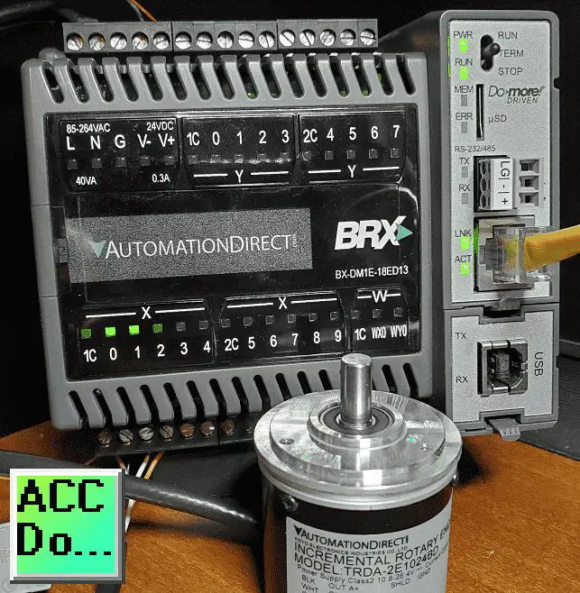 We will be looking at the wiring of an incremental encoder to our BRX Do-More PLC. The A, B, and Z phases will be connected. Using the high-speed input menus in the Do-More Designer programming software we will specify the counter mode of operation. We will also scale the input so we can determine the revolutions per minute (RPM) rate. This will be monitored on our data view window. Let’s get started with the BRX Do-More PLC High-Speed Input Counter.
Previously in this BRX series PLC, we have discussed:
System Hardware – Video
Unboxing – Video
Installing the Software – Video
Establishing Communication – Video
Firmware Update – Video
Numbering Systems and Addressing – Video
First Program – Video
Monitoring and Testing the Program – Video
Online Editing and Debug Mode – Video
Timers – Video
Counters – Video
High-Speed IO – Video
Compare Instructions – Video
Math Instructions – Video
Program Control – Video
Shifting Instructions – Video
Drum Instruction – Video
Serial Communication – Modbus RTU to Solo Process Temperature Controller – Video
Data Logging – Video
Email – Text SMS Messaging Gmail – Video
Secure Email Communication Video
AdvancedHMI Communication – Modbus TCP – Video
Analog IO – System Configuration – Video
HTTP JSON Instructions – Video
Analog Dusk to Dawn Program – Video
INC DEC 512 Registers for DMX512 – Video
PID with PWM Output – Video
PID Ramp Soak Profile – Video
Do-More Simulator MQTT Publish / Subscribe – Video
BRX Do-More PLC MQTT Communications – Video
Stride Field Remote IO Modules Modbus TCP Ethernet
– Unboxing SIO MB12CDR and SIO MB04ADS Video
– Powering and Configuring Video
BRX Do-More PLC to Stride Field IO Modbus TCP – Video
BRX Do-More PLC Ethernet Remote IO Controller BX-DMIO
– Unboxing BX-DMIO Video
– Configuration and Programming Video
Modbus RTU TCP Remote IO Controller BX-MBIO
– Hardware Video
– Powering and Configuring Video
BRX Do-More PLC to Modbus Remote IO Controller BX-MBIO – Video
Modbus ASCII Protocol – Video
Peerlink Ethernet Communication – Video
HTTP Web Server – Video
Dynamic Web Pages – Video
BRX Do-More PLC FTP Client Get Put – Video
Do-More Designer Element Browser – Video
Our entire BRX Do-More series can be found here.
The programming software and manuals can be downloaded from the Automation Direct website free of charge.
Watch the video below to see an encoder wired and programmed with the BRX Do-More PLC.
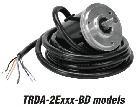
TRDA-2E Series Incremental Encoder
Looking at the specifications of this incremental encoder we can determine if this will work with our BRX Do-More PLC.
 The electrical specifications will include the operating range, maximum response frequency, output type, etc.
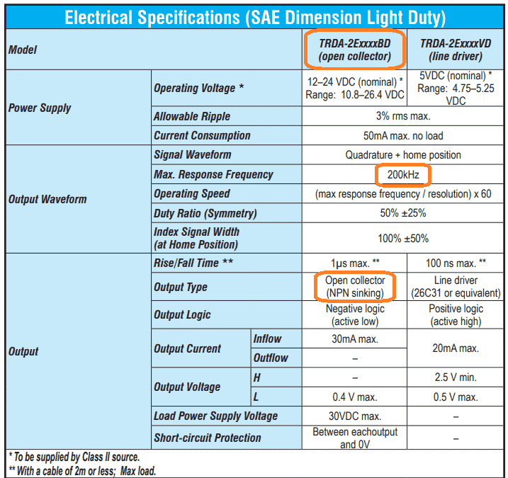 The BRX Do-More input will accept a 250 kHz signal so a 200 kHz from this encoder will work fine. An open collector NPN sinking output is used for the encoder output. This means that the PLC input would be sourcing, positive switching.
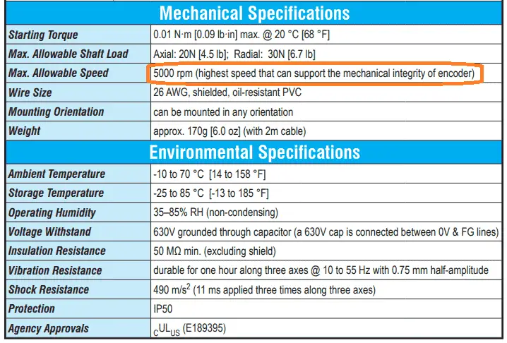 The maximum RPM for the encoder is 5000. We will also be fine with the temperature range of this incremental encoder.
TRDA-2E Series Timing Chart
Here is the timing chart for our incremental encoder.
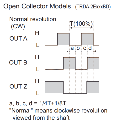 You will see that we have three outputs. Output Z phase will give one pulse per one revolution of the encoder. A and B phases will give the pulses to our PLC. The number of pulses will be set according to the model of the incremental encoder. In our case, we are receiving 1024 pulses per revolution. Phase A leads Phase B by 90 degrees when the encoder is moving clockwise. (CW) B will lead A by 90 degrees when the encoder is moving counterclockwise. (CCW) This leading and lagging will determine the direction in which the encoder is moving.
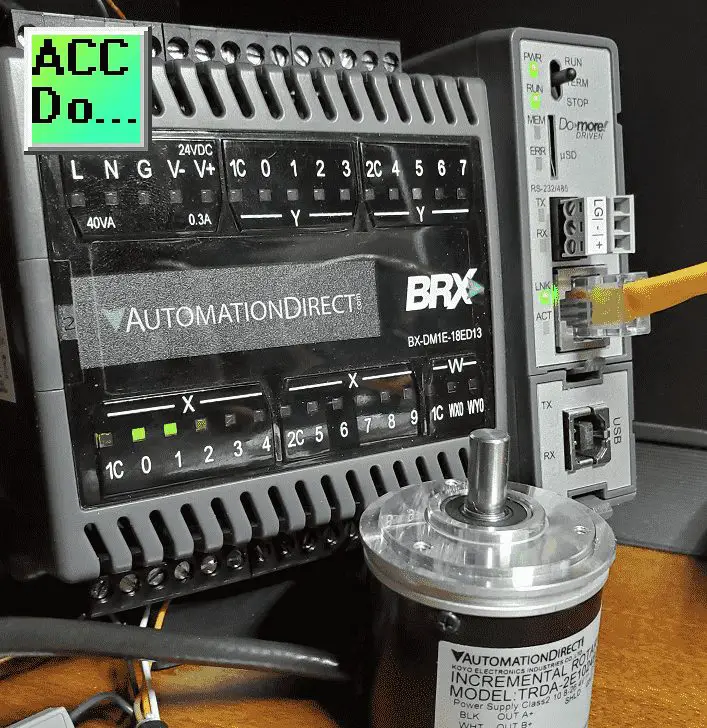
Wiring Incremental Encoder to BRX Do-More PLC
The DC inputs of the BRX PLC can be sinking or sourcing.
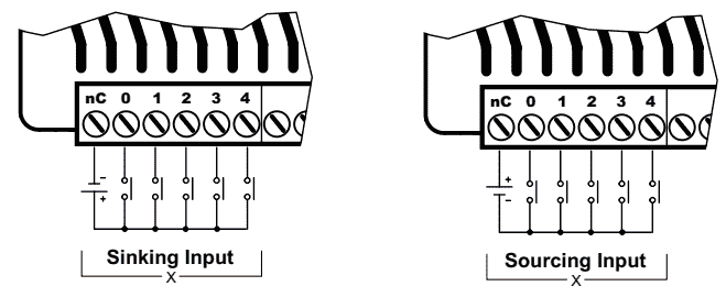 The common of the PLC inputs will be 0 VDC for sinking and + VDC for sourcing.
Here is the wiring diagram for our incremental encoder.
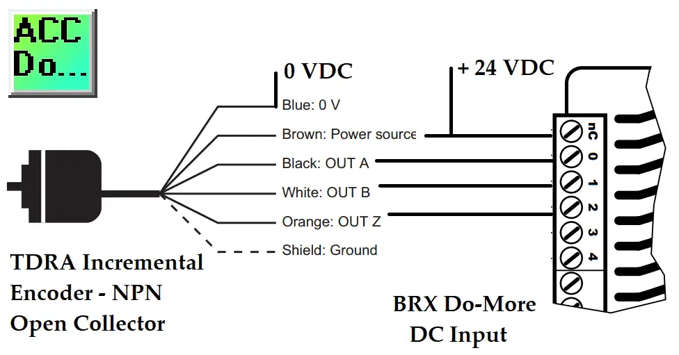 Since the encoder is an NPN open collector the input to the PLC will be sourced. This means that the common will be at +24 VDC.
BRX Do-More High-Speed Input Counter Programming
The first thing that we need to do is configure the inputs.
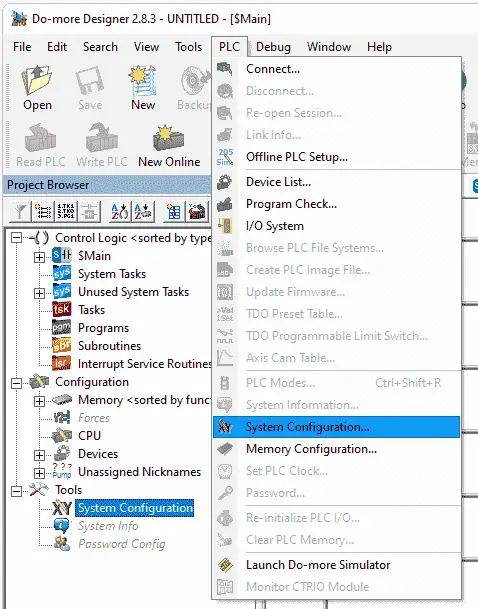 Call up the system configuration window by selecting it under tools in the project browser. You can also use the main menu | PLC | System Configuration…
 The third way is to select the icon on the main menu.
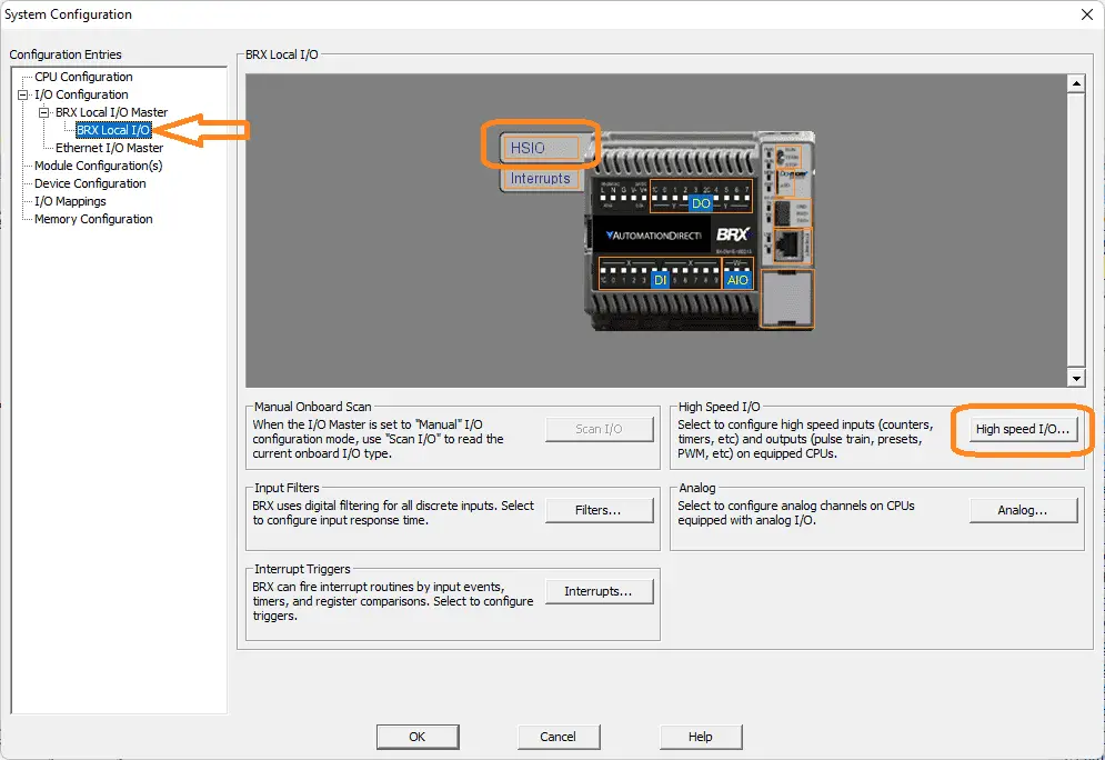 On the left-hand side of the system configuration window, select BRX Local I/O. We can now select the HSIO from the picture when you move your mouse over it or the High-Speed I/O button.
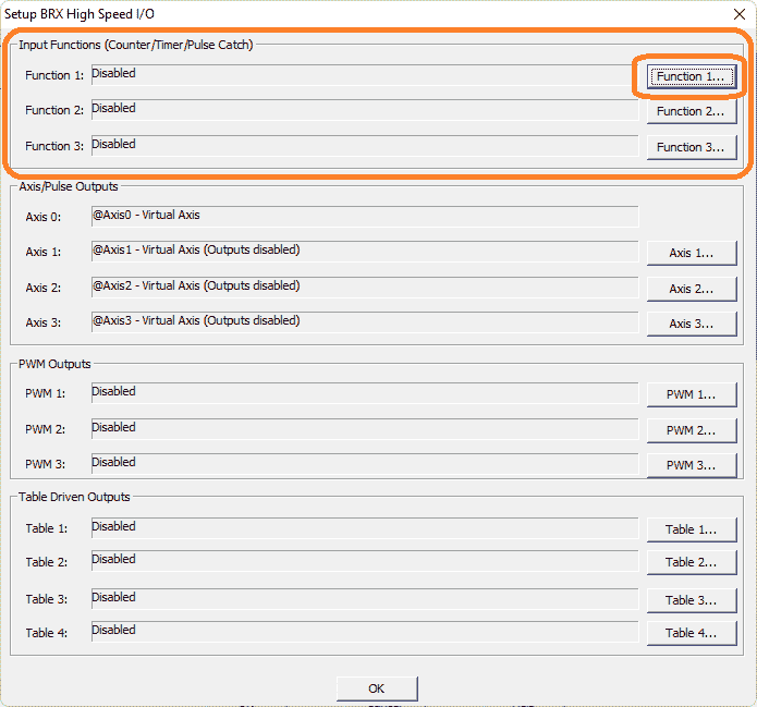 This will display the Setup BRX High-Speed I/O window. You can see that we can program in three different functions for the input. Select the Function 1… button.
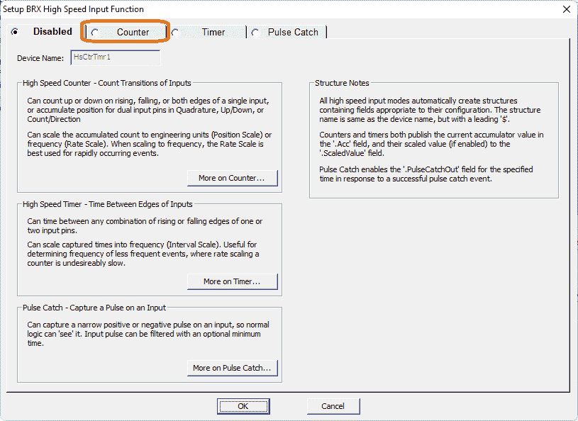 The default is to have the function disabled. You will see that the default device name is HsCtrTmr1. This sets up the structure for the high-speed input function 1. A description of the three different modes is shown. Select the Counter tab along the top of the window.
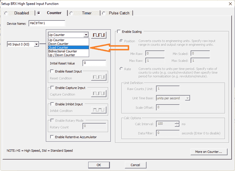 The default input is X0 with the selection of Up Counter. We will select Quad (Quadrature) Counter. This will use the A and B phases of the incremental encoder.
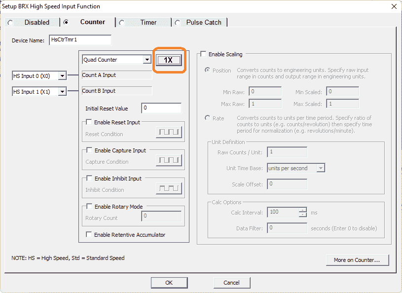 The inputs for the A and B phases use HS Input 0 (X0) and HS Input 1 (X1). This is how we currently have the encoder wired to the PLC. You can change this by selecting the drop-down menu and selecting the input you want to use for each of the inputs. The 1X button will allow you to multiply the number of pulses of the incremental encoder. (1X, X2, X4)
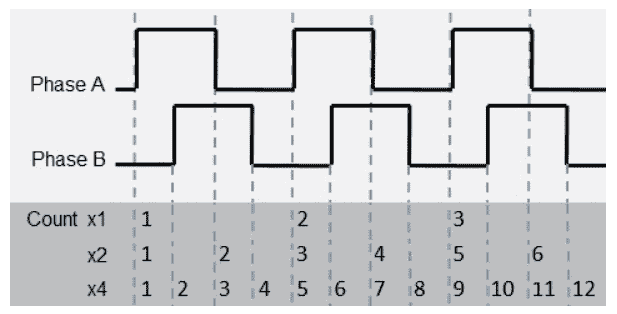 An incremental encoder will give you a number of pulses per revolution. In my case, this is 1024 PPR. (Pulses Per Revolution) Each count will take place on the transition from off to on in a normal operation. (1X) The X2 count will count on the leading and trailing edges of the input count. This will give us 2048 counts per revolution. X4 will give a count on the leading and trailing edges of both inputs. (A and B phases) This will give us 4096 PPR. Changing this count multiplier will not change the input frequency response. This will still be 250 Khz. We will leave the multiplication factor at its default of 1X.
Initial Reset Value – The default is 0. This is the value of the accumulator of the counter when a reset signal is received. This can be in the PLC ladder logic or physical input.
Enable Reset Input – Optionally specify one of the High-Speed discrete inputs that will stop the current count operation. The current count value will be cleared or set to the Initial Reset Value. If the Counter Type is Quad Counter this is typically the zero (Z phase) or index input from an encoder or a reference signal. The Condition configures the input to execute either on the rising edge, falling edge, high level, or low level of the specified input. Clicking the button cycles through the edge and level selections.
Enable Capture Input – Optionally specify one of the High-Speed discrete inputs that will capture the current count value when the specified input signal changes state. This Count Capture operation must be enabled by turning ON the capture enable structure member ($DeviceName.EnableCapture). At that point, when the required input signal is received, the current count value is copied to $DeviceName.CapturedValue and $DeviceName.CountCaptured is turned ON. To repeat the capture operation, the capture enables bit $DeviceName.EnableCapture must be turned OFF, then turned back ON.
Enable Inhibit Input – Optionally specify one of the High-Speed discrete inputs that will cause the counter to stop counting input pulses. Any time the Inhibit input is ON, the current pulse count value is maintained and any new pulses are not counted. When the Inhibit input is no longer active new pulses will be counted.
Enable Rotary Mode (only available for Quad, Bi-Directional, and Up / Down Counters)
Input pulses that originate from a rotary source are expected to generate count values that wrap at a certain count value. One positive pulse at the maximum value will wrap the Current Count value to 0. One negative pulse at 0 will wrap the Current Count to the maximum value. The range of count values will be 0 to (Rotary Count – 1).
Enable Retentive Accumulator – Optionally make the current count value in the accumulator retentive, meaning that it will retain its current value through a loss of system power. For this option to work correctly the high-speed counter’s associated structure also must be marked as retentive in the Memory Configuration. See help file.
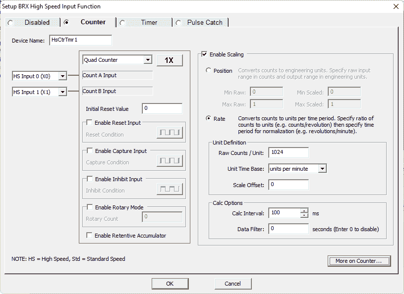 The scaling function converts the pulse count into a distance or position through Position Scaling, or into a speed, flow rate, or velocity through Rate Scaling. When scaling is enabled, each time a new scaled value is computed it will be placed in the $DeviceName.ScaledValue structure field.
In our case, we will use this to show revolutions per minute. (RPM) Select the rate option. Under the raw counts/units enter 1024. This is the count for one revolution. The unit time base is set for units per minute. The calculation option is set for 100 milliseconds. This will be the update time in our scaled value memory address.
Select the OK button.
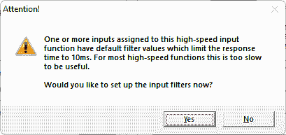 The Do-More Designer software checks to ensure that the filters are set for the high-speed input counter. If they are not then this warning is given. Select yes to set the filters.
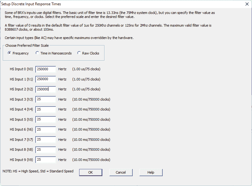 The setup discrete input response times window will allow us to set the first three inputs (A, B, Z phases of our incremental encoder) to 250 000 pulses per second. (250 kHz) Select OK.
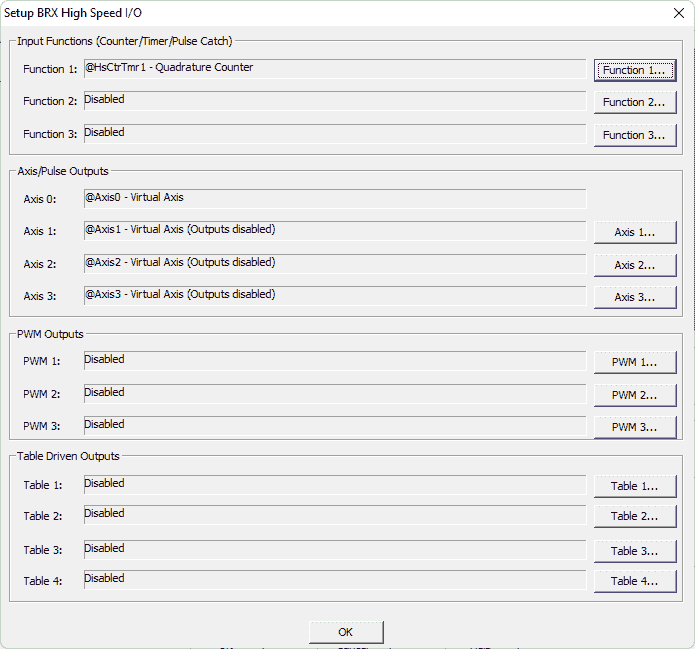 Our high-speed input counter is now set up in our Do-More Designer software. Select OK.
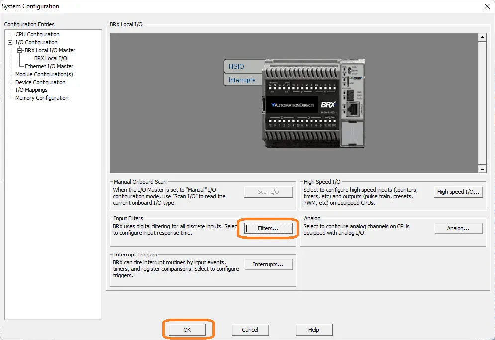 On the system configuration window, you can see that we could also set the discrete input filters by selecting the filters button. Select OK.
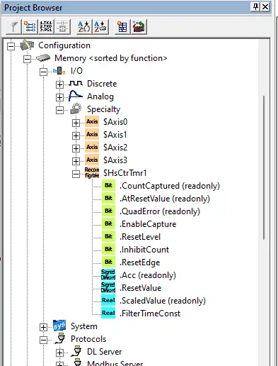 In the project browser window under I/O you will be able to see the structure for the high-speed input counter that we just programmed. ($HsCtrTmr1)
We can now use this structure in the BRX Do-More PLC ladder logic.
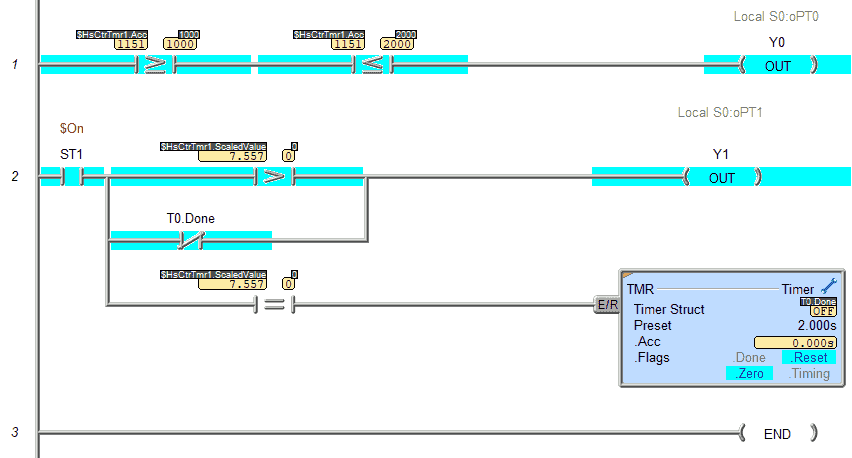
If the high-speed counter accumulated value is between 999 and 1999 output Y0 will be on in the first rung. Rung 2 determines if motion is detected. If the rate of the high-speed input is greater than 0, output Y1 will turn on. This will remain on until the rate is 0 for 2 seconds.
Download the program to the BRX Do-More PLC.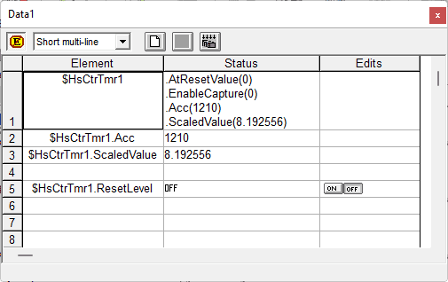 Use the data monitor to view the structure and watch the values as the encoder pulses come in. These values can then be used in your ladder logic program.
 Watch the video below to see this high-speed input counter in action on our BRX Do-More PLC.
Download the BRX Do-More program here.
BRX Series PLC from Automation Direct – Power to deliver
Overview Link (Configure and purchase a system)
Manuals and Product Inserts (Installation and Setup Instruction)
Do-More Designer Software (Free Download Link) – The software will contain all of the instruction sets and help files for the BRX Series PLC.
Watch on YouTube: BRX Do-More PLC High-Speed Input Counter
If you have any questions or need further information please contact me.
Thank you,
Garry
If you’re like most of my readers, you’re committed to learning about technology. Numbering systems used in PLCs are not difficult to learn and understand. We will walk through the numbering systems used in PLCs. This includes Bits, Decimal, Hexadecimal, ASCII, and Floating Point. To get this free article, subscribe to my free email newsletter.
Use the information to inform other people how numbering systems work. Sign up now. The ‘Robust Data Logging for Free’ eBook is also available as a free download. The link is included when you subscribe to ACC Automation.