A Proportional-Integral-Derivative algorithm is a generic Control Loop feedback formula widely used in industrial control systems. A PID algorithm attempts to correct the error between a measured process variable and the desired setpoint by calculating and then outputting a corrective action that can adjust the process accordingly and rapidly, to keep the Error to a minimum.
Here are some references on PID control:
PID without a Ph.D. By Tim Wescott
Understanding PID in 4 minutes
PID Control – A brief introduction
PID Controllers Explained
Who Else Wants to Learn about On-Off and PID Control?
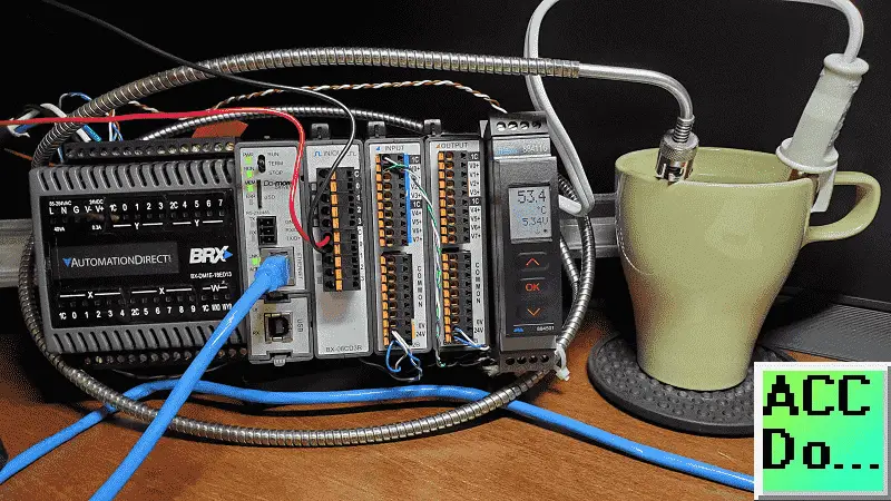
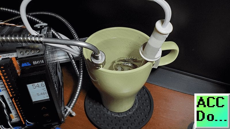
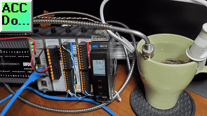
We will be using an immersion heater in a cup of water to keep the temperature at a constant value. Using the Do-More Designer software we will perform an autotune on our PID instruction.
Our immersion heater will be controlled through a relay using time proportional control from our PID output. Let’s get started!
Previously in this BRX series PLC, we have discussed:
System Hardware – Video
Unboxing – Video
Installing the Software – Video
Establishing Communication – Video
Firmware Update – Video
Numbering Systems and Addressing – Video
First Program – Video
Monitoring and Testing the Program – Video
Online Editing and Debug Mode – Video
Timers – Video
Counters – Video
High-Speed IO – Video
Compare Instructions – Video
Math Instructions – Video
Program Control – Video
Shifting Instructions – Video
Drum Instruction – Video
Serial Communication – Modbus RTU to Solo Process Temperature Controller – Video
Data Logging – Video
Email – Text SMS Messaging Gmail – Video
Secure Email Communication Video
AdvancedHMI Communication – Modbus TCP – Video
Analog IO – System Configuration – Video
HTTP JSON Instructions – Video
Analog Dusk to Dawn Program – Video
INC DEC 512 Registers for DMX512 – Video
Our entire series can be found here.
https://accautomation.ca/series/brx-do-more-plc/
The programming software and manuals can be downloaded from the Automation Direct website free of charge.
Watch the video below to see the PID with PWM instructions in action on our BRX PLC.
BRX D0-More Thermocouple Input (Feedback)
We will be using a J type thermocouple for our temperature sensor. This will be connected to our universal signal conditioner. Our universal signal conditioner will convert this into a 0-10VDC linear output. This will be wired into the analog card of the BRX PLC.
The Universal Signal Conditioner and Isolator post will explain the wiring and programming of this unit. (Video)
I know that we could have used a BX-04THM card so we can wire our thermocouple input directly. This is what I had available and it will allow us to view the current temperature in the video below.
BRX Do-More Wiring
The analog output from our universal signal conditioner (0-10VDC) will be connected to our first Analog Input point. Please see BRX PLC Analog IO – System Configuration for more details. The scaling for our analog input will be 0– 10VdDC = 0 to 100 degrees Celsius.
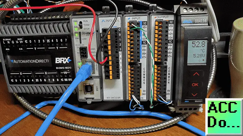
Y8 will be our relay output on our BX-08CD3R card that will turn on and off our heater. This relay is wired in series with the heater. See the video below for the wiring and operation of our PID instruction in the BRX PLC.
System Configuration (Analog Input)
Call up the system configuration by selecting it under the Tools menu in the Project Browser. You can also use the main menu | PLC | System Configuration…
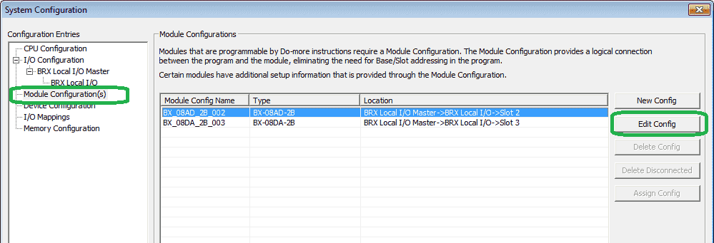
Select Module Configuration(s) on the left side. Select the analog input card. (BX_08AD_2B_002) Then select the Edit Config button on the right side.

Select the Analog Input 0-3 tab. Our analog input 0 will be provided a DC Voltage of 0 – 10. Select the enable scaling from WX1 to RX1. Our scaling factors will be as follows:
WX1 Min 0.0 VDC = RX1 Min 0 degrees Celsius
WX1 Max 10.0 VDC = RX1 Max 100 degrees Celsius
After transferring our configuration to the controller we can monitor our data view elements.
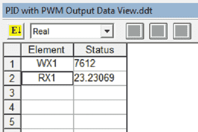
RX1 will show our scaled analog input representing the temperature of the water in Celsius degrees.
BRX Do-More Ladder Logic
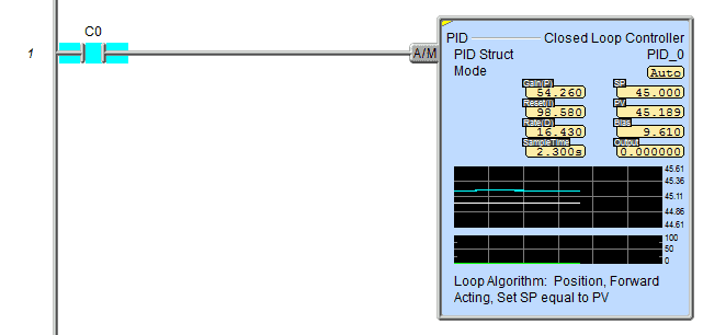
We will now add our PID Closed Loop Controller instruction.
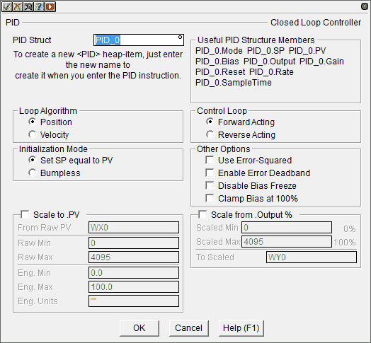
All of our settings will be left as their default. Our structure name will be PID_0 for our first loop.
Loop Algorithm – Position – This is the choice for most applications which include heating and cooling loops as well as the most position and level control loops.
Control Loop – Forward Acting – A forward (direct) acting control loop means that whenever the output value increases, the process variable will also increase.
Initialization Mode – Set SP equal to PV – Automatically sets the Output equal to the Bias and the Setpoint equal to the Process Variable when control switches from manual to automatic.
Select OK.
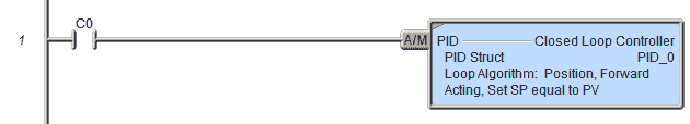
We will use internal contact C0 to switch between manual and automatic for our PID loop.
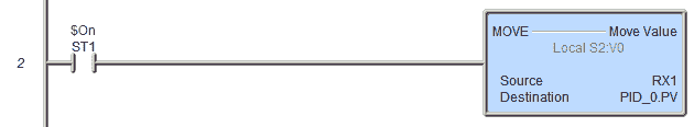
The current temperature of our water (Scaled analog input RX1) will be transferred to our present value (PV) of our PID_0 loop. This will happen with every scan of the PLC.
PWM Output
The pulse width modulated output will be controlled by the time proportional control instruction. (TIMEPROP)
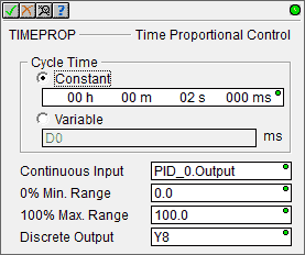
Our cycle time will be set for 2 seconds. The PID_0 loop output will be varied from 0.0 to 100.0 percent. Y8 will be on for this percentage of the 2-second cycle.
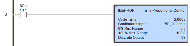
The TIMEPROP instruction will be executed every scan of the PLC.
Set PID Tuning Constants
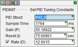
The PIDINIT instruction will set the PID loop parameters for initialization. If your program does not have this instruction after auto-tuning your PID loop, then the software will prompt you to put this instruction into your program.
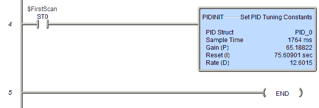
The first scan will activate the initial parameters of our PID_0 loop.
This is our entire program.
Status Monitoring / PID Overview
When monitoring the status of our PID instruction, you will see all of the parameters. The present value (PV) and set value (SV) graph will be displayed along with a graph of the output percentage. This is a good tool to monitor your loops quickly.
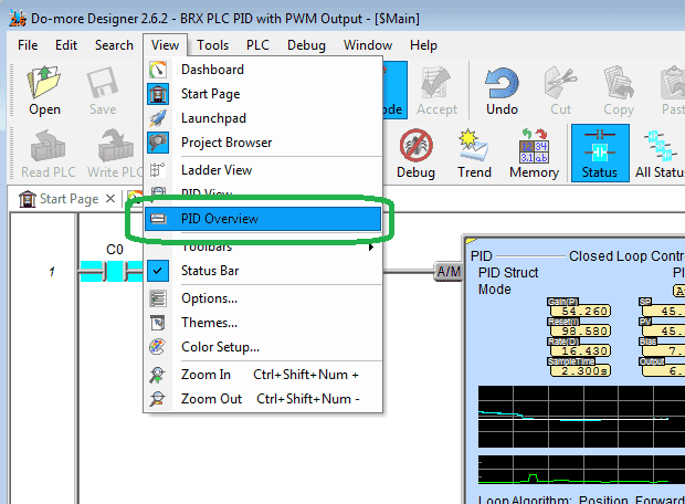
On the main menu select View | PID Overview.
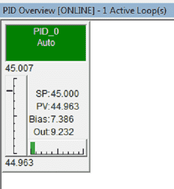
This will show you the PID loops that you have programmed in a simple easy to read display.
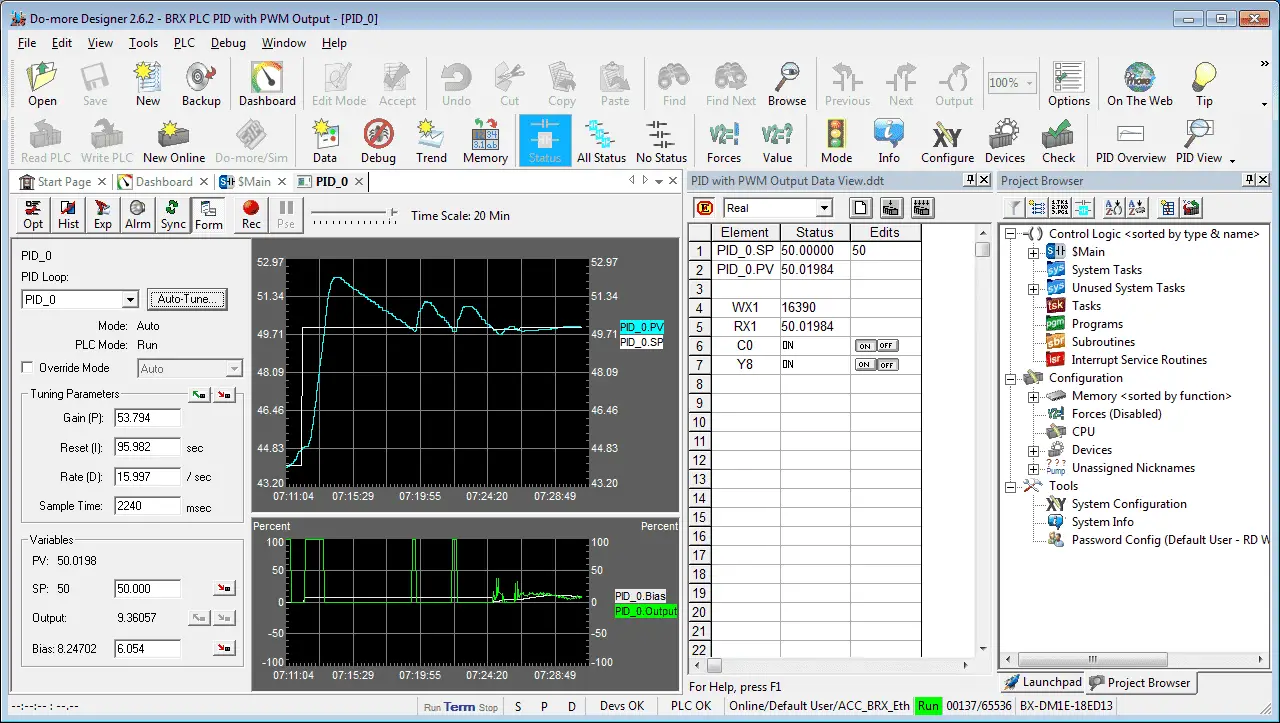
PID View / Auto Tuning
The PID View is where the majority of the work related to configuring, tuning, and monitoring PID loops will be done. The PID View is opened by selecting Debug-> PID View from the Online Toolbar, or right-clicking on any PID instruction in a ladder diagram and selecting Trend Instruction from the pop-up menu, or double-clicking on the PID Overview graphic for that PID loop.
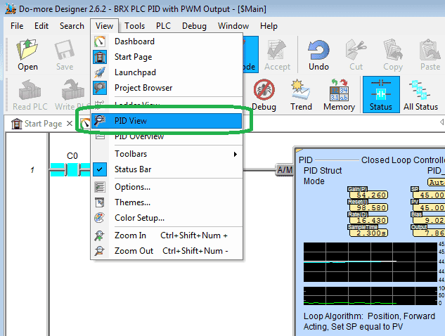
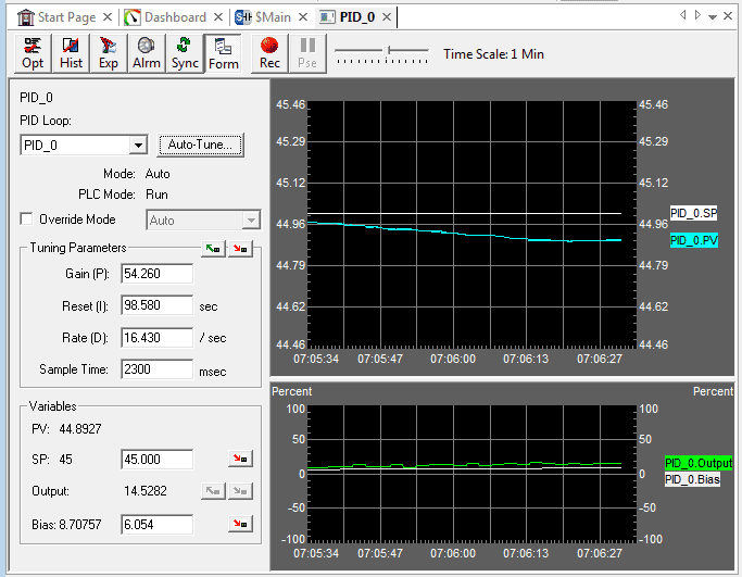
On the main menu when online select View | PID View.
If you have more than one PID loop you will be asked to select the loop that you wish to view.
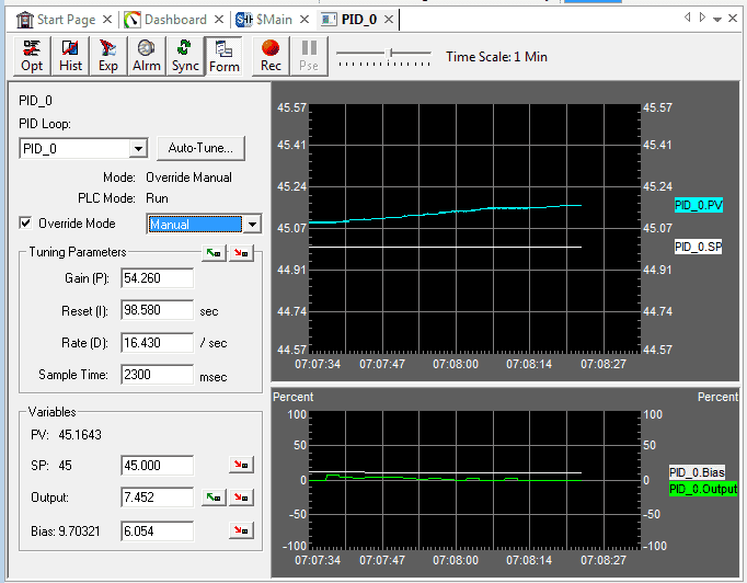
Select the Override Mode and choose the Manual mode. As you watch the video below, we first tried to auto-tune the process in manual mode. When automatic mode switched over our SP was changed to the PV. This is because our PID instruction had Set SP equal to PV for the Initialization Mode. See the above instruction.
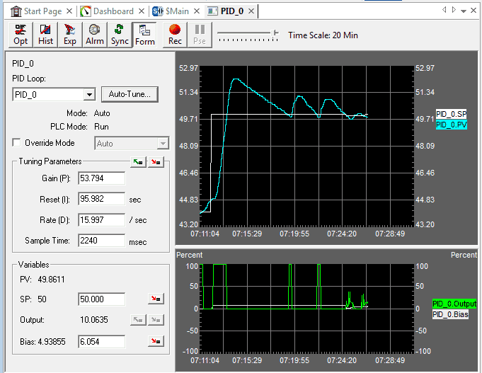
Set the override mode to Automatic.

Change the setpoint (SP) to 50 and hit the button to the right to transfer that SP number into the PLC.
Select the Auto-Tune… button.
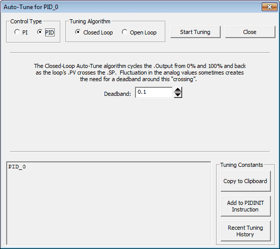
Our control type will be PID and our tuning algorithm will be closed loop. We will leave the Dead band at 0.1. Select the Start Tuning button.
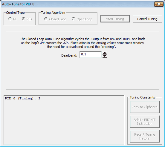
Our automatic tuning has now started for PID_0.
During the tuning process, the output will be on 100% of the time until the PV crosses over the SV. The output will then be at 0% until the PV falls below the SV. This process will continue until the PID parameters are turned. (2 -3 Cycles)
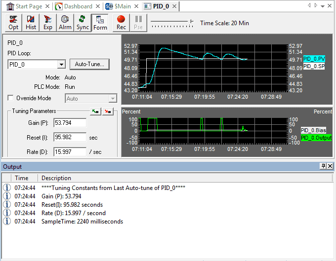
Once the automatic tuning is finished, the parameters will be displayed on the output screen.
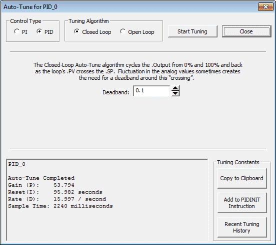
Our Auto-Tune for PID_0 window will also show that the tuning is complete.
You will see three options for our tuning results on the right side of the parameters.
Copy to Clipboard
A copy of the parameters is placed on the clipboard to be used later to paste into the PIDINIT instruction.
Add to PIDINIT Instruction
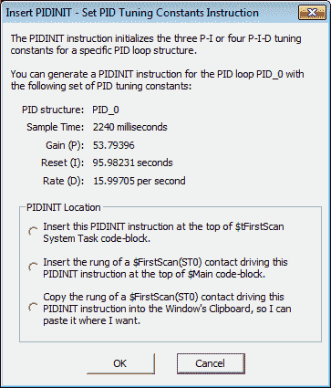
Here you will be given the choice of where to copy the rung of logic for the PIDINIT instruction.
Recent Tuning History
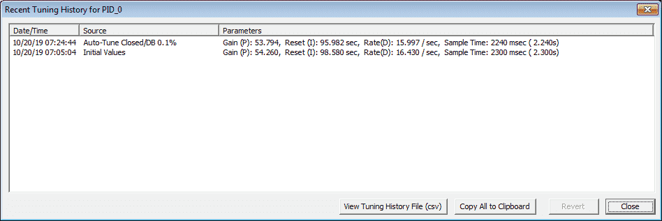
This will show you the history of tuning.
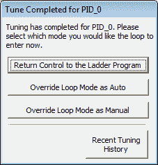
After tuning is complete the controller will return to the mode controlled by the rung for the PID instruction.
Watch the video below to see the PID control and Auto-tuning in action on our BRX Series PLC.
You can download the program here.
BRX Series PLC from Automation Direct – Power to deliver
Overview Link (Configure and purchase a system)
Manuals and Product Inserts (Installation and Setup Instruction)
Do-More Designer Software v2.0.3 (Free Download Link) – The software will contain all of the instruction sets and help files for the BRX Series PLC.
Watch on YouTube: BRX PLC PID with PWM Output
If you have any questions or need further information please contact me.
Thank you,
Garry
If you’re like most of my readers, you’re committed to learning about technology. Numbering systems used in PLC’s are not difficult to learn and understand. We will walk through the numbering systems used in PLCs. This includes Bits, Decimal, Hexadecimal, ASCII and Floating Point.
To get this free article, subscribe to my free email newsletter.
Use the information to inform other people how numbering systems work. Sign up now.

The ‘Robust Data Logging for Free’ eBook is also available as a free download. The link is included when you subscribe to ACC Automation.
Garry,
I’m going to purchase the items in your PID with PWM series.
I don’t currently have any BRX components, and to purchase everything I see, the cost will be around $1200US. In one of the pictures, it looks like the analog output card (BX-08DA-2B) isn’t being used here. If not, that would save me $277US, plus the cost of the terminals. Could you please let me know if I need this card or not? It would be greatly appreciated. I was going to order an analog card for my DL205 setup, but I’m using a Do-More CPU and I don’t think that CPU will work with the F2-8AD4DA-2 analog card.
Thank you very much!
Hi Dan,
In the series, I have gone through all of the different components. The BRX CPU unit has one analog input and output onboard the unit. You would not have to purchase any analog cards.
Here is a link to the BRX unit that I am using.
https://www.automationdirect.com/adc/shopping/catalog/programmable_controllers/do-more_series_(brx,_h2,_t1h)_plcs_(micro_modular_-a-_stackable)/brx_series_plcs_(stackable_micro_brick)/18_point_micro_plc_units_(bx_18-z-18e)/bx-dm1e-18ed13
Regards,
Garry