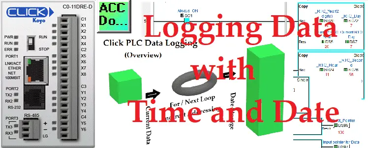
We will now look at logging data with time and date in the Click PLC. The Click PLC can perform indirect addressing. This means that I can ask for information to be moved to and from locations in the PLC using a pointer that will indicate the address.
Stephen Covey in The 7 Habits of Highly Effective People said: “Begin With the End in Mind.” This is especially true when looking at storing or logging data within the programmable logic controller. (PLC) It is important to fully define what you want to accomplish with your program.
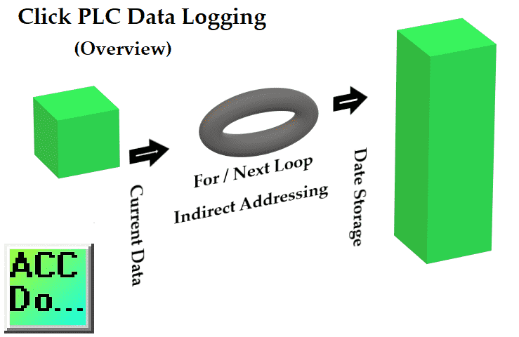
In our Click PLC example, we want to take a series of consecutive memory locations (DS1 to DS10) and store them in memory areas DS100 to DS4100 each minute. We will be able to store 400 entries (400 minutes) in our storage area. Every entry will include the real-time clock (RTC) of the Click. This will show the date and time of each entry. Let’s get started!
Previously in this series, we have discussed:
System Hardware – Video
Installing the Software – Video
Establish Communication – Video
Numbering System and Addressing – Video
Timers and Counters
– Counter Video
– Timer Video
Compare and Math Instructions – Video
Program Control Instructions – Video
Shift Register – Video
Drum Instruction – Video
Send and Receive Instructions – Video
AdvancedHMI Communication – Video
Firmware Update – Video
HMI Rotary Encoder Dial Input – Video
High Speed Counters Part 1
– High-Speed Count Mode Video
– Interval Measurement Mode Video
– Duration Measurement Mode Video
– Frequency Measurement Mode Video
High Speed Counters Part 2
– External Interrupt Mode Video
– Pulse Catch Mode Video
– Filter Pulse Mode Video
– Frequency Measurement and High-Speed Count Mode Video
Wiring Stack Light to Click PLC – Video
Wiring Push Buttons and Selector Switch to Click PLC – Video
– Test and Assembly of Push Buttons and a Selector Switch – Video
Wiring an Inductive Proximity NPN PNP Sensor to the Click PLC – Video
Wiring a Capacitive Proximity NPN PNP Sensor to the Click PLC – Video
Wiring an Ultrasonic Proximity Sensor to the Click PLC – Video
– Unboxing our UK1F Ultrasonic Proximity Sensor – Video
Analog Dusk to Dawn Program – Video
PID using Factory IO – Video
PID Instruction and Autotuning using Factory IO – Video
Our entire series can be found here.
The programming software and manuals can be downloaded from the Automation Direct website free of charge.
Watch the video below to see the Click PLC controller store data with a time and date stamp.
Click PLC Indirect Addressing – Logging Data
Indirect addressing is supported in the Click PLC. The manuals refer to this as ‘Pointer Addressing’. It will utilize the DS registers as the offset value and can be used with the DS, DD, DF, DH, XD, YD, TD, CTD, and TXT data register memory types.
Example:
DD[DS3] – This will point to the address in DD that the DS3 value contains. If DS3 has a value of ‘145’ then the address will use DD145. As we change DS3 the corresponding address of DD will change as well. We can copy values to that location (logging) and read values from that location (retrieving).
Here are some additional links to show how indirect addressing works:
– Here is a Method that is Helping PLC Programmers to Program Faster
– Building PLC Program that you can be Proud of – Part 1
Setting Up Our Logged Data in the Click PLC
As mentioned above we will be setting all of the logged data in a consecutive memory area in the PLC. We will be using DS1 to DS10. This will include the real-time clock (RTC) information.
DS1 = Current bit information to log
DS2 = Timer Value
DS3 = Additional Data to store
DS4 = Additional Data to store
DS5 = Year
DS6 = Month
DS7 = Day
DS8 = Hour
DS9 = Min
DS10 = Sec
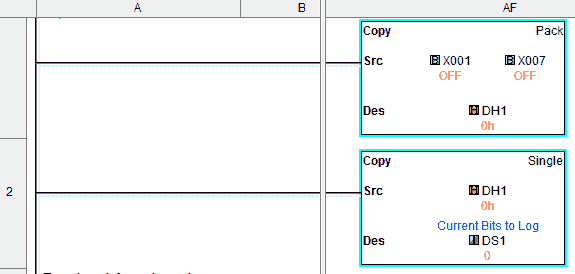
X1 to X7 will be copied to DH1. DH1 will be copied to DS1. This is the way in the Click to move individual bit numbers into the DS area.
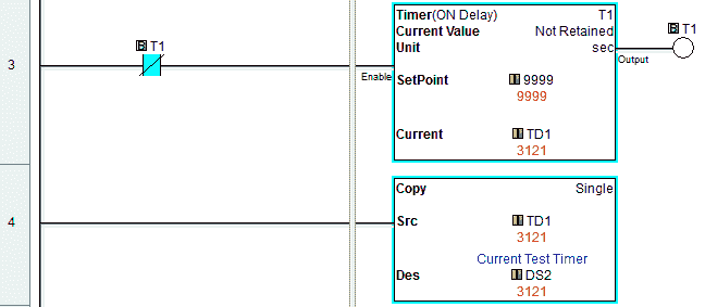
A timer that is self-resetting will be added to the log.
This will be stored in DS2.
DS3 and DS4 will be left empty. This can be any data you want to store like counters, numbers, or additional timers.
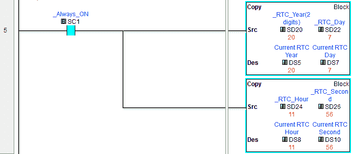
The Click RTC year (SD20), month (SD21) and day (SD22) are stored in DS5, DS6, and DS7. Hour (SD24), minute (SD25) and seconds (SD26) are stored in DS8, DS9, and DS10. You will see that the copy instruction can move consecutive memory locations.
We have now set up our information to be logged.
Initial / Reset of our Indirect Pointer Location – Data Logging
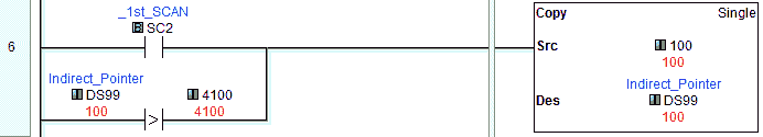
Our indirect address pointer will be at DS99. The first scan of the PLC will reset the pointer to 100. Our logged data will start at DS100.
If we go beyond the maximum storage area assigned (DS4100) then reset the pointer back to 100. (DS100)
Setting Up for For Next Loop in the Click PLC
A For/Next loop instruction will be used in our example. This is used to repeat a section of code (rungs of logic) between the For and Next instructions.
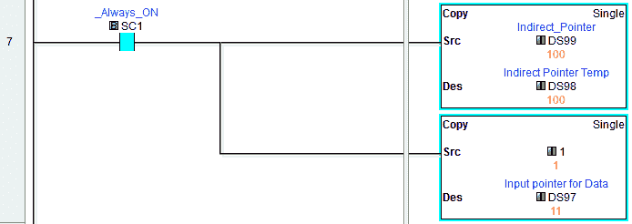
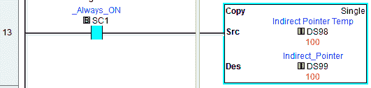
Take the indirect pointer value in DS99 and copy it to DS98. We will also set up an input data pointer for our logged data location (DS97). This is set to a value of 1. The 1 will represent DS1 indirectly in our loop.
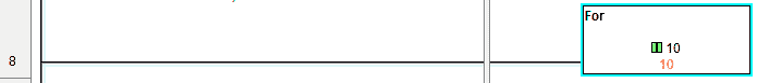
The For instruction will set up the loop and specify the number of times that the code between the For and Next instructions will execute within the scan. In our case, this will be set for 10. Each of these cycles through the loop will move our logged data.
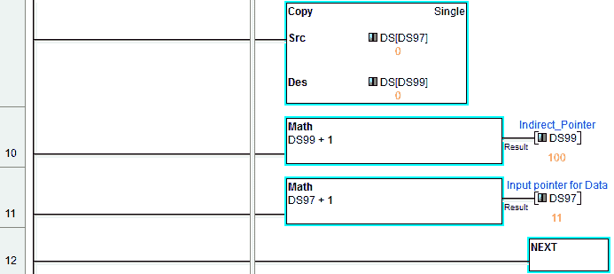
Copy indirectly the input data to the indirect address pointer each time through the loop. When the Next instruction is reached the scan will return to the For instruction until the number of times required is reached. The following will break down each of the scans through our For / Next loop and the pointer location values.
1st pass
DS[DS97] = DS1 copy to DS[DS99] = DS100
Increment DS97 = 2
Increment DS99 = 101
2nd pass
DS[DS97] = DS2 copy to DS[DS99] = DS101
Increment DS97 = 3
Increment DS99 = 102
3rd pass
DS[DS97] = DS3 copy to DS[DS99] = DS102
Increment DS97 = 4
Increment DS99 = 103
4th pass
DS[DS97] = DS4 copy to DS[DS99] = DS103
Increment DS97 = 5
Increment DS99 = 104
ETC.
10th pass
DS[DS97] = DS10 copy to DS[DS99] = DS109
Increment DS97 = 11
Increment DS99 = 110
Reset our Indirect Pointer
We will reset our indirect pointer DS99 back to its original value prior to the For / Next loop instructions.
Note: Since we are running this code every scan (Main Program), our current logged values will be set for every scan in the storage area. DS100 to DS1400
Triggering our Logged Data based on Event – Click PLC
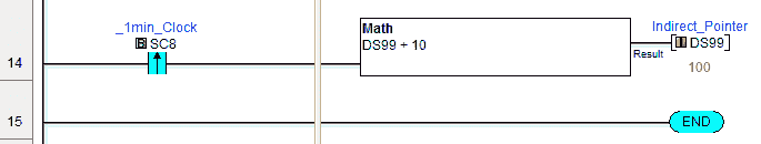
When the leading edge of the one-minute system bit happens, the indirect pointer (DS99) will increment by 10. This will keep the previous scans logged information and start logging the values using the new indirect location to store.
Monitoring our Data Logging in the Click PLC
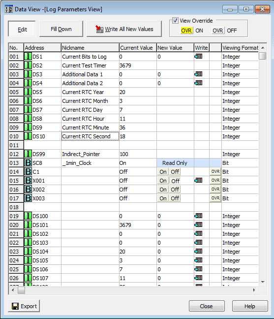
We can use the Data View to see our program in operation.
Note: PLC programs can be written in several different ways and get the same results. A modification from this program could be to use a subroutine for the For / Next loop. The logging trigger would be the condition for the subroutine. I have included this as another example. The programs can be downloaded below.
Watch the video below to see the data logging in action on our Click PLC. An additional C1 bit will be put in the logging trigger to demonstrate this program.
Download the Click PLC programs here.
Click PLC Support Links
The Click PLC can be programmed using free Click programming software from Automation Direct. Here is a link to the software.
https://support.automationdirect.com/products/clickplcs.html
The following links will help you to install the software and establish communication.
https://accautomation.ca/click-plc-installing-the-software/
https://accautomation.ca/click-plc-establish-communication/
The entire Click PLC series can be found at the following URL:
https://accautomation.ca/series/click-plc/
Watch on YouTube: Click PLC Logging Data with Time and Date Stamp
If you have any questions or need further information please contact me.
Thank you,
Garry
If you’re like most of my readers, you’re committed to learning about technology. Numbering systems used in PLC’s are not difficult to learn and understand. We will walk through the numbering systems used in PLCs. This includes Bits, Decimal, Hexadecimal, ASCII and Floating Point.
To get this free article, subscribe to my free email newsletter.
Use the information to inform other people how numbering systems work. Sign up now.

The ‘Robust Data Logging for Free’ eBook is also available as a free download. The link is included when you subscribe to ACC Automation.