Now You Can Have Robust Data Logging for Free – Part 1
Now You Can Have Robust Data Logging for Free – Part 2
Now You Can Have Robust Data Logging for Free – Part 3
Now You Can Have Robust Data Logging for Free – Part 4
Now You Can Have Robust Data Logging for Free – Part 5
Now You Can Have Robust Data Logging for Free – Part 6
Now You Can Have Robust Data Logging for Free – Part 7
Computer Program Visual Basic (VB6) Continue
We have started our VB program and have set up our Adodc connections to the database. Let’s continue by setting the labels up with the Adodc connections. Then we will set up the communications to the Do-More PLC and put information into our Access 2007 (*.accdb) database. (AccRL.accdb)

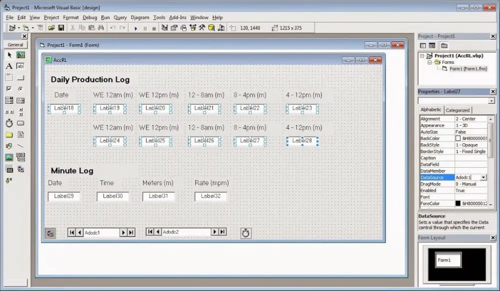
Select all of the labels that will be for the Production_Log table and set the properties. Under DataSource, select Adodc1. Do the same thing for all the labels under the Minute_Log table.
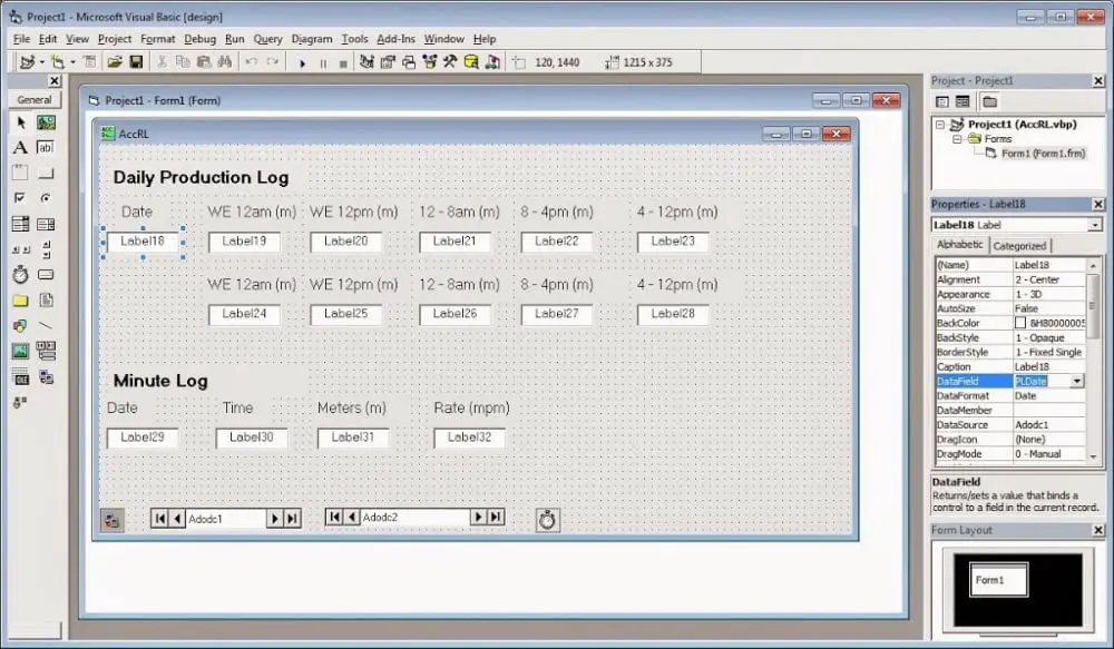
Now go through each label and select the data field it represents. Do this for both the Production_Log table and the Minute_Log table.
Note: You can also set the format in which the field will display
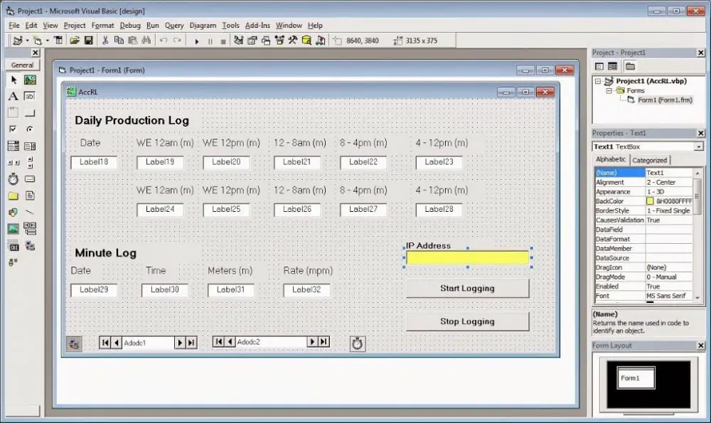
We now have our primary display set up in visual basic. The last thing we will do is add a text box and command buttons to control the logging of the information.
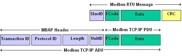
http://www.simplymodbus.ca/TCP.htm
All Modbus Commands:
| Function Code | Action | Table Name |
| 01 (01 hex) | Read | Discrete Output Coils |
| 05 (05 hex) | Write single | Discrete Output Coil |
| 15 (0F hex) | Write multiple | Discrete Output Coils |
| 02 (02 hex) | Read | Discrete Input Contacts |
| 04 (04 hex) | Read | Analog Input Registers |
| 03 (03 hex) | Read | Analog Output Holding Registers |
| 06 (06 hex) | Write single | Analog Output Holding Register |
| 16 (10 hex) | Write multiple | Analog Output Holding Registers |
A review of the numbering systems can be found on a previous blog here.
In part 8, we will continue with writing the VB6 program. We will start to put everything together in the program using the code.
If you have any questions or need further information, please get in touch with me.
Thank you,
Garry
If you’re like most of my readers, you’re committed to learning about technology. Numbering systems used in PLCs are not challenging to learn and understand. We will walk through the numbering systems used in PLCs. This includes Bits, Decimals, Hexadecimal, ASCII, and Floating Points.
To get this free article, subscribe to my free email newsletter.
Use the information to inform other people how numbering systems work. Sign up now.

The ‘Robust Data Logging for Free’ eBook is also available as a free download. The link is included when you subscribe to ACC Automation.