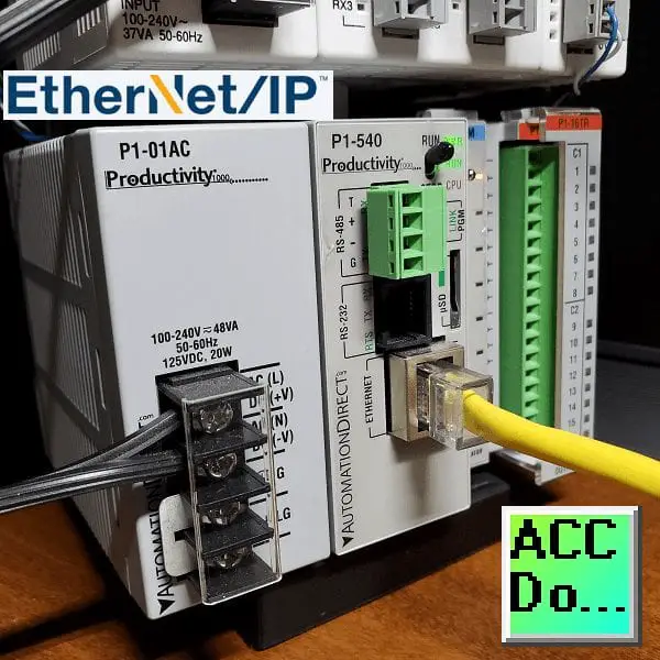
We will now utilize Ethernet/IP to connect a Click PLC as remote IO on a Productivity system. The productivity series of controllers can use explicit and implicit messaging techniques of EtherNet/IP to optimize data exchanges across the network.
Explicit messaging means that the data messages that are transmitted will contain everything needed in order to respond or decode the message. It is a normal client/server relationship with instructions explicitly spelled out in the data messages. This communication happens at times that the Client requests the information.
Implicit messaging means the data messages are streamlined. The device is configured ahead of time to know what to do with the data. This is used for time-critical messages and it functions as a typical scanner/adapter relationship. Implicit messaging is real-time. It has the ability to copy data with minimal additional information because both ends already know exactly what each bit and byte.
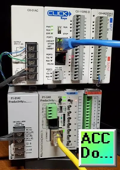
A Click PLC will be set up as remote distributed inputs and outputs for our Productivity 1000 controller. Implicit Ethernet IP will be set up. The Click will be the Ethernet IP adapter and the Productivity will be the Ethernet IP scanner. Let’s get started.
Previously in this Productivity 1000 series PLC, we have discussed:
Productivity Suite Simulator – Video
System Hardware – Video
Installing the Software – Video
Establishing Communication – Video
First Program – Video
Documenting the Program – Video
Monitoring and Testing the Program – Video
Online Editing and Debug Mode – Video
Numbering Systems and Tag Database – Video
Contact and Coil Instructions – Video
Timer Instructions – Video
Counter Instructions – Video
Math Instructions – Video
Data Handling Instructions Part 1 – Video
Data Handling Instructions Part 2 – Video
Array Functions Part 1 – Video
Array Functions Part 2 – Video
Array Functions Part 3 – Video
Program Control – Video
Drum Sequencer Instructions – Video
Data Logger – Video
Web Server – Video
Modbus RTU Serial Communication – Video
Modbus TCP Ethernet Communication – Video
Firmware Update – Video
AdvancedHMI Modbus TCP Ethernet Communication – Video
Email and Text Communication – Video
PID Instruction – Video
PID Ramp Soak Instruction – Video
Modbus ASCII Protocol – Video
Stride Field Remote IO Modules Modbus TCP Ethernet
– Unboxing SIO MB12CDR and SIO MB04ADS Video
– Powering and Configuring Video
Productivity 1000 PLC to Stride Field IO Modbus TCP – Video
Modbus RTU TCP Remote IO Controller BX-MBIO
– BX-MBIO Hardware Video
– BX-MBIO Powering and Configuring Video
Productivity 1000 PLC to Modbus TCP RTU Remote IO Controller BX-MBIO – Video
Our entire P1000 series can be found here.
The programming software and manuals can be downloaded from the Automation Direct website free of charge.
Watch the video below to see the Click PLC act as remote IO for our Productivity PAC using Ethernet/IP implicit (I/O) messaging.
Click Ethernet/IP Adapter Setup
System Configuration
The two types of messaging that CLICK supports on top of the CIP (Common Industrial Protocol) layer are IO Messaging (also called Class 1 Implicit) and Explicit Messaging (through Class 3 or Unconnected). We will be using IO messaging for our remote application to the productivity. The adapter is set up the same way for both methods of Ethernet/IP.
In the Click, Programming Software call up the system configuration menu. This is done by selecting the main menu | Setup | System Configuration…
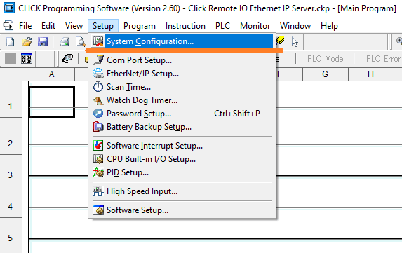
You can also access this by selecting System Configuration under the CPU Configuration in the Function tab of the Navigation panel of the software.
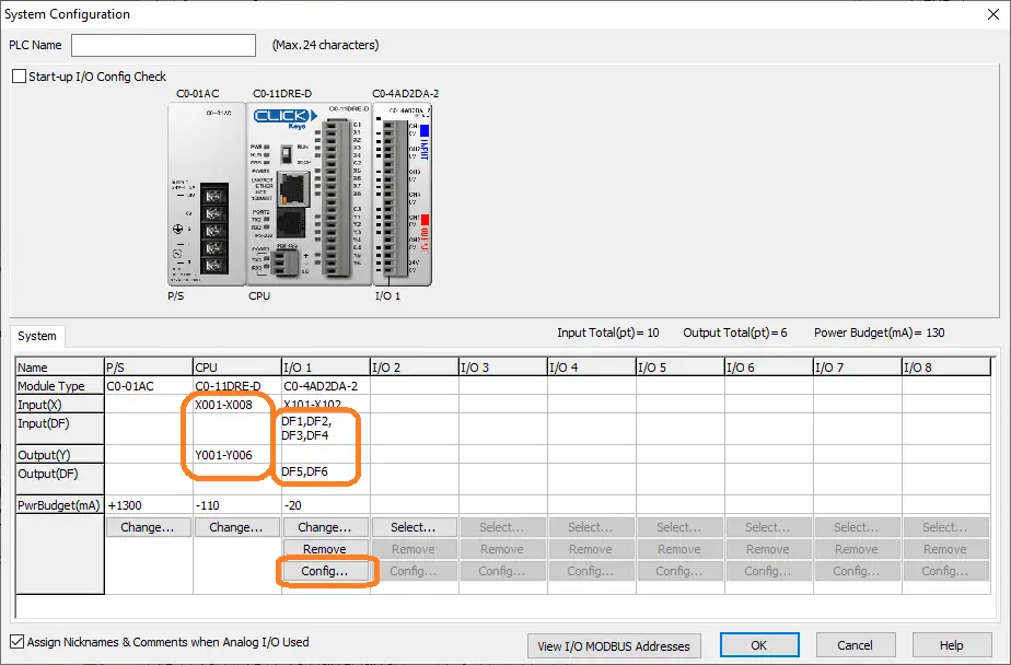
The system configuration window will show you the addresses of the inputs and outputs of our Click hardware.
X001 to X008 are the inputs that are channel XD0 (32-Bit) of the Click.
Y001 to Y006 are the outputs that are channel XY0 (32-Bit) of the Click.
Analog inputs are in DF1 to DF4 and are 32-Bit Floating or real values.
Analog outputs are in DF5 and DF6 and are 32-Bit Floating or real values.
Select the Config… button under the analog card.
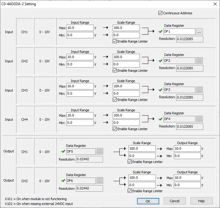
This is where you would set up the analog input and output configuration.
Ethernet Com Port Setup
Select Com Port Setup… from the main menu | Setup.
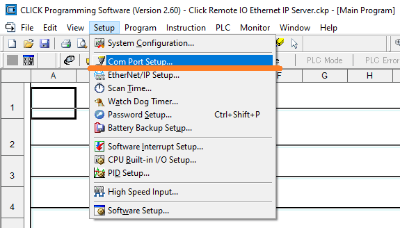
You could also select Com Port 1 Setup under the CPU configuration in the Function tab of the Navigation panel.
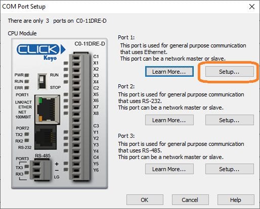
Select Setup…
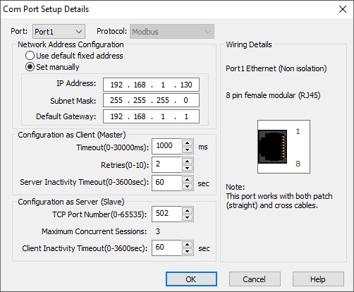
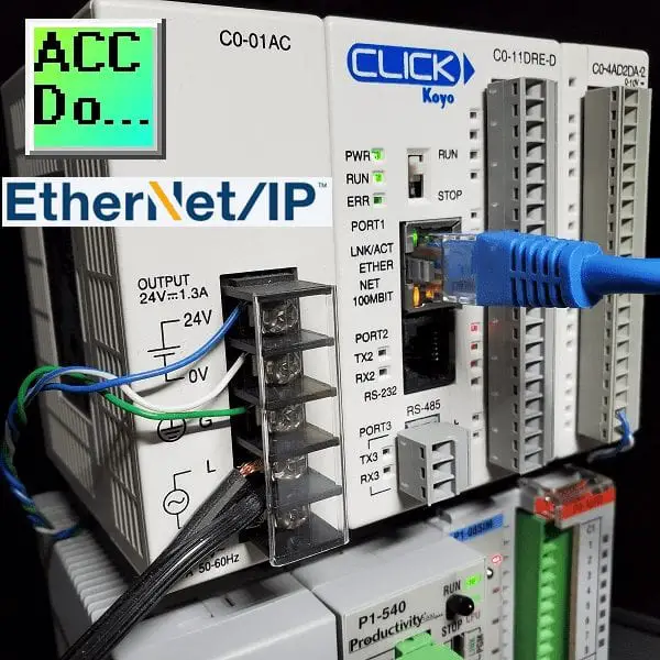
Port 1 is our Ethernet port of the Click PLC. Select manual and enter a static (fixed) IP address and subnet mask for our network. This static address is required because we want to ensure that the Ethernet/IP scanner will be able to find this controller.
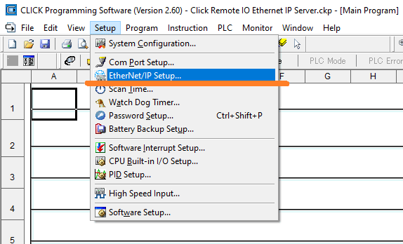
Click EtherNet/IP Setup
Select Ethernet/IP Setup… from the main menu | Setup.
Alternatively, you can also select EtherNet/IP under Com Port 1 in the CPU configuration. This is located on the Function tab of the navigation panel.
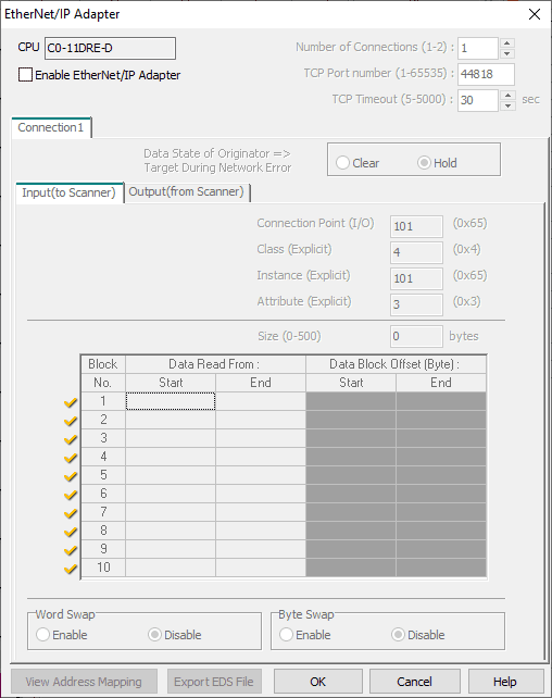
The EtherNet/IP Adapter window will now appear.
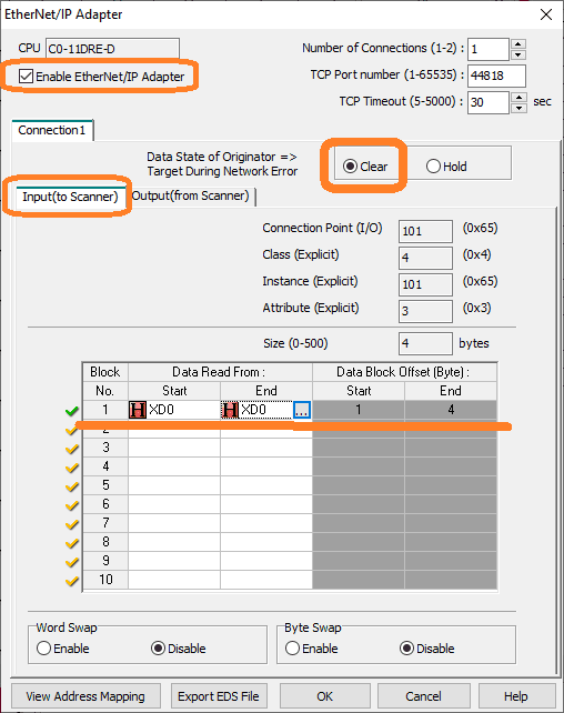
Select enable EtherNet/IP Adapter. You will see connection 1 appear.
Select clear for the data state of originator target during network error. Since we are using this as remote I/O usually this will be reset.
Input (to Scanner)
Our connection point (I/O) defaults to 101. This information is required for the scanner. We enter under block number 1 the start of XD0 and the end of XD0. The size is 4 bytes, which is 32 bits.
Select Output (from Scanner).
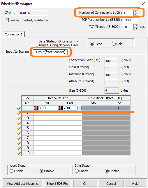
Enter under block number 1 the start of YD0 and the end of YD0. The size is 4 bytes, which is 32 bits. Our output connection point (I/O) defaults to 102.
Select 2 under the number of connections at the top right of the EtherNet/IP Adapter window.
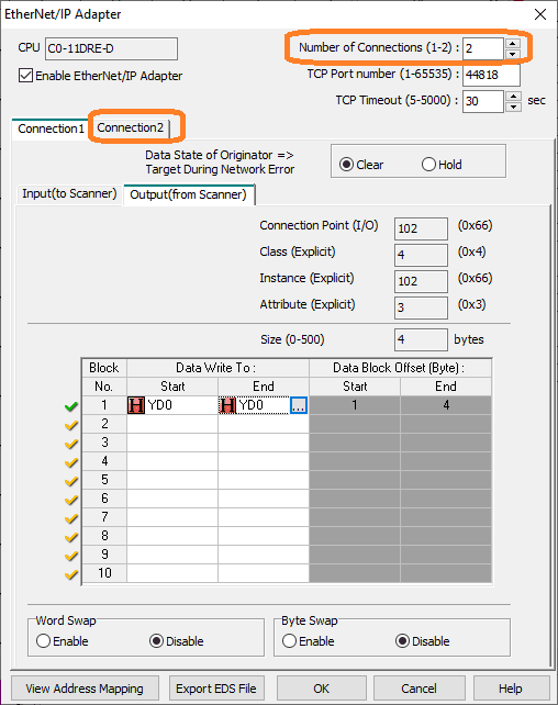
Connection 2 will now appear as a tab. Select it.
We will now enter the data for the analog inputs and output. This is done as a separate connection because it is floating-point instead of binary bits.
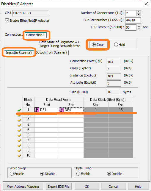
The input block 1 will be DF1 to DF4. This is 16 bytes of data and the connection point is 103. Ensure the Clear is selected if an error occurs in communication.
Select output.
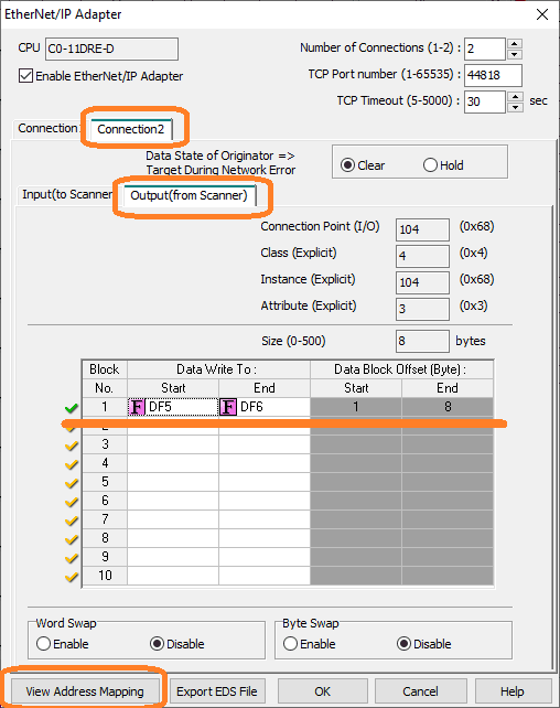
The output block 1 will be DF5 to DF6. This is 8 bytes of data and the connection point is 104.
Select view address mapping located on the bottom left of the window.
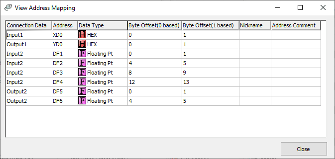
This will display all of the addresses that we have programmed on our Ethernet/IP Click Adapter.
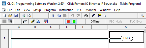
Add an end statement to the ladder logic. Our Click remote IO Ethernet IP server program is complete.
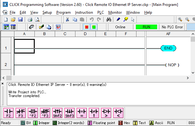
Transfer the program to our Click PLC.
While online with the Click PLC program monitor the scan time.
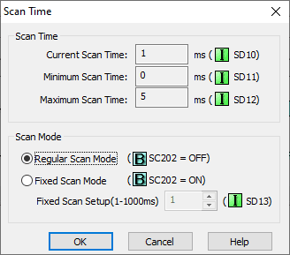
This scan time window can be viewed by selecting the main menu | Setup | Scan Time…
The scan time maximum is 5 milliseconds. We will use this number and set our Ethernet IP Scanner to update every 10 milliseconds for the I/O messaging.
Productivity EtherNet/IP Client Setup
Productivity Ethernet Port Setup
We will now set up the Productivity Series Controller to communicate Implicit I/O Messaging.
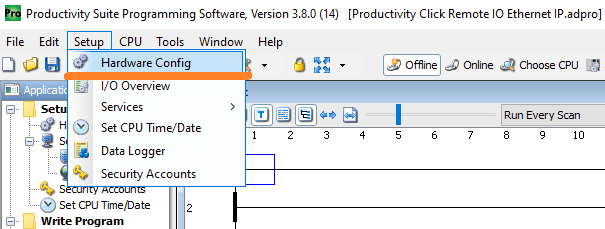
Select hardware configures from the main menu | Setup.
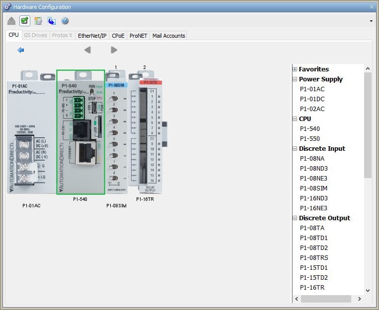
Double click on the P1-540 CPU unit on the hardware configuration window.
On the P1-540 window select the Ethernet Port tab.
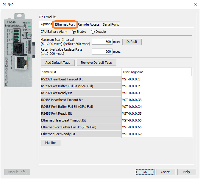
Set the IP address and subnet mask for the network.
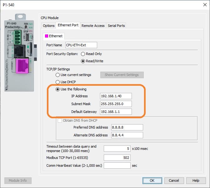
You can also set the default gateway and DNS addresses if you wish. I always like to work with fixed IP addresses.
Productivity EtherNet/IP Client
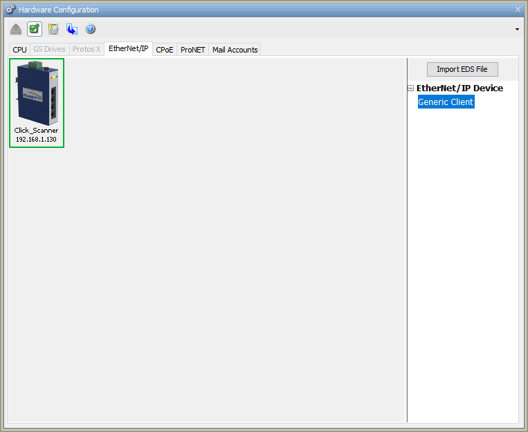
Select the Ethernet IP tab of the hardware configuration window.
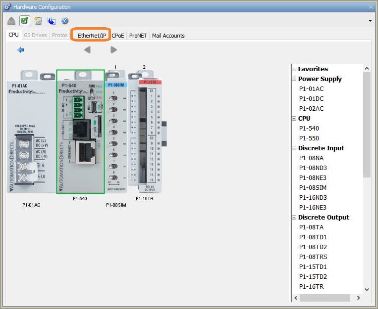
This will then display the Ethernet/IP clients configured.
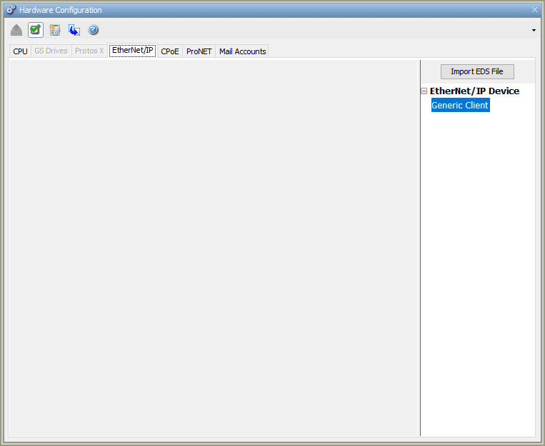
Double click on the Generic Client under the EtherNet/IP Device.
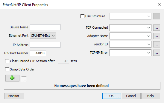
You can also left-click and drag the generic client onto the blank page. This will then display the EtherNet/IP Client properties window.
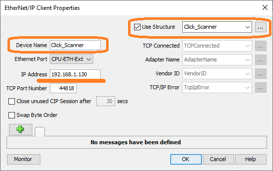
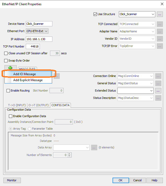
Select use structure and give it a name. Click_Scanner is used for the structure and device name. Type in the address of the Click Ethernet/IP Adapter from above. We will leave all of the other settings as their default. Click the green plus icon.
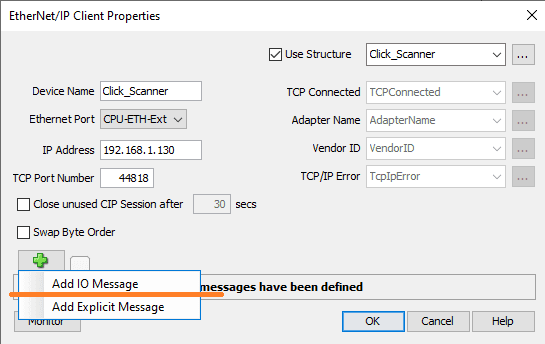
Select add IO Message. This sets implicit messaging for our productivity Ethernet IP scanner.
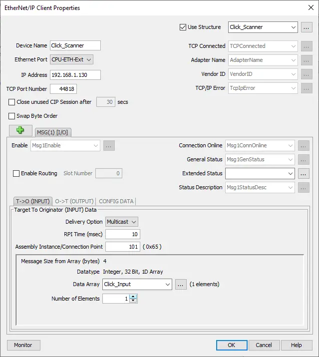
MSG(1) I/O tab will now be displayed. Three tabs will now be available. The first tab ‘Target to Originator (INPUT) Data’ is automatically selected.
We will leave all fields as their default and fill in the following:
RPI (Request Package Interval) Time (msec) = 10
Assembly Instance/Connection Point = 101 – This is the same as the inputs connection point set in the Click above.
Data Array will be called Click_Input and the number of elements will be 1.

Define the tag as Integer, 32 Bit, 1D Array with 1 column. Select OK. This will match the 4 bytes of information that the connection point is looking to obtain.
Select the ‘Originator to Target (OUTPUT) Data’ tab.
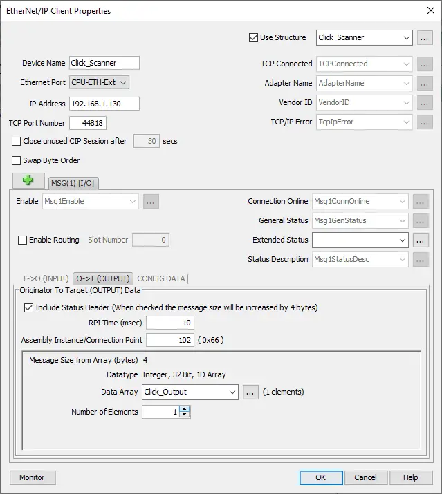
We will leave all as the default except for the following:
RPI Time (msec) = 10
Assembly Instance/Connection Point = 102 – This is the same as the output connection points set in the Click above.
Data Array will be called Click_Output and the number of elements will be 1.
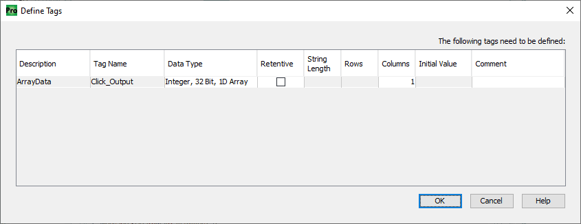
Define the tag as Integer, 32 Bit, 1D Array with 1 column. Select OK. This will match the 4 bytes of information that the connection point is looking to obtain.
Select the ‘CONFIG DATA’ tab.
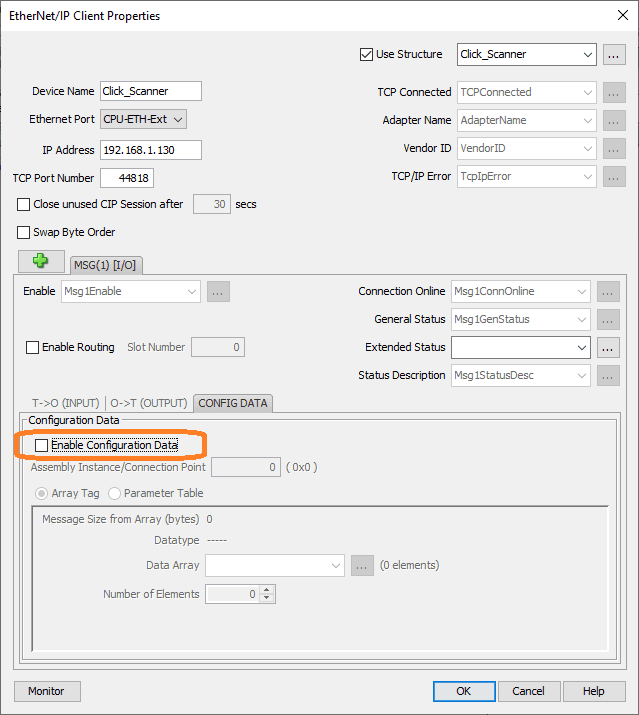
Ensure that the enable configuration data is not selected.
We will now program in the analog input and output information. Select the green plus icon again and select ‘Add IO Message’.
Select MSG(2) IO tab.
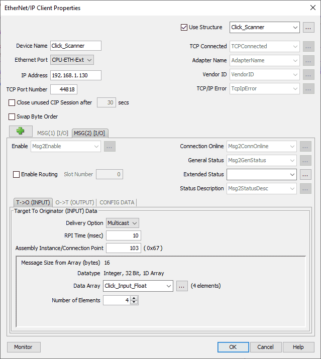
‘Target to Originator (INPUT) Data’ tab will be displayed.
We will leave all fields as their default and fill in the following:
RPI (Request Package Interval) Time (msec) = 10
Assembly Instance/Connection Point = 103 – This is the same as the Analog Input connection point set in the Click above.
Data Array will be called Click_Input_Float and the number of elements will be 4.
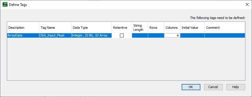
Define the tag as Integer, 32 Bit, 1D Array with 4 columns. Select OK. This will match the 16 bytes of information that the connection point is looking to obtain.
Select the ‘Originator to Target (OUTPUT) Data’ tab.
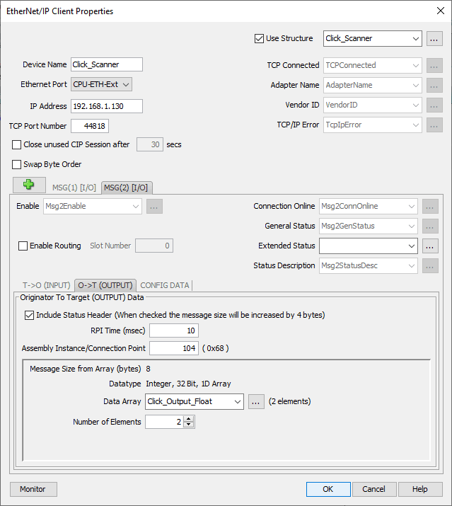
We will leave all as the default except for the following:
RPI Time (msec) = 10
Assembly Instance/Connection Point = 104 – This is the same as the analog output connection points set in the Click above.
Data Array will be called Click_Output_Float and the number of elements will be 2.
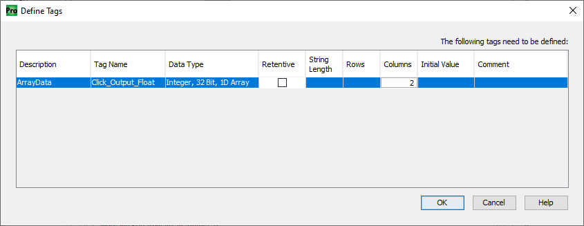
Define the tag as Integer, 32 Bit, 1D Array with 2 columns. Select OK. This will match the 8 bytes of information that the connection point is looking to obtain.
Select the ‘CONFIG DATA’ tab.
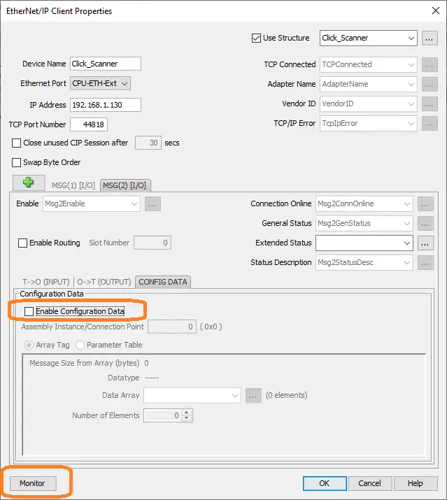
Ensure that the enable configuration data is not selected.
Select the Monitor button on the bottom left side of the window.
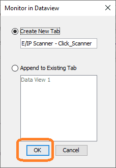
This will add a new tab in the Dataview for us to monitor the Ethernet/IP Scanner in the Productivity Suite software. Select OK.
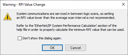
A warning about the request package interval will be displayed. This is to ensure that the value is not lower than the average scan time. Select OK.
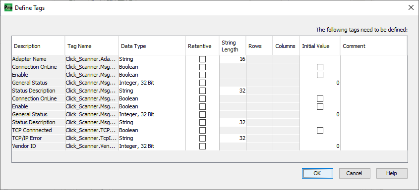
We can now define the tags used in our Click scanner. Leave everything as their default and select OK.
Our productivity Ethernet/IP click scanner has now been programmed.
Productivity Click Remote IO Program
Our simple ladder logic program will ensure that the Click scanner message 1 and 2 are enabled.
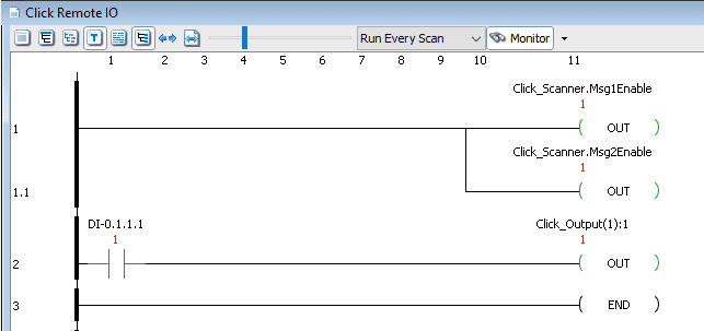
We will also add the first input on the productivity simulator card that will control the first output relay on our click. Save the program.
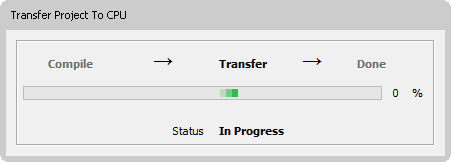
Transfer the program to the controller.
While we are online to the productivity CPU, check the scan time.
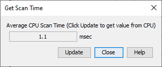
The ‘get scan time’ window can be displayed by selecting it from the main menu | CPU| Get CPU Scan Time.
Since the remote IO will update every 10 milliseconds, we are well within our local scan times on each controller.
Watch the video below to see the Click PLC act as remote IO to the Productivity 1000 PAC controller.
Monitoring the Productivity Click EthernetIP Remote IO
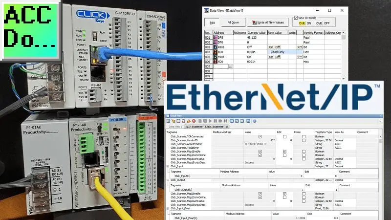
Call up the data view monitoring in the productivity suite software.
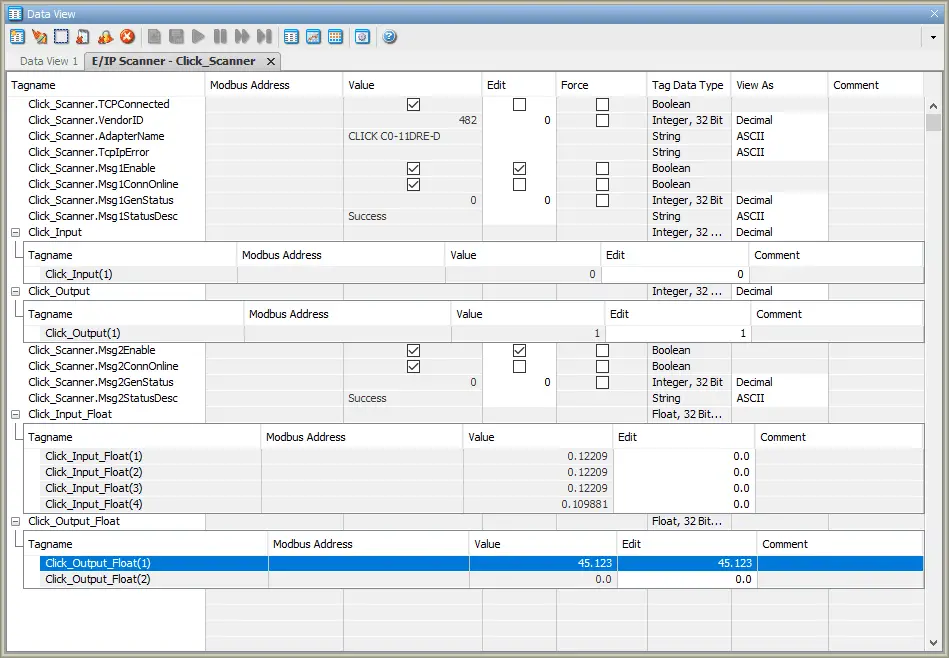
The E/IP scanner Click Scanner tab was created when we selected the monitor above. We can now test the communications.
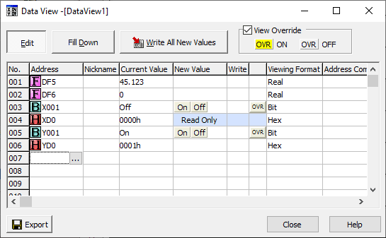
Call up the data view monitoring in the click programming software.
We can view the IO in the Click through this software.
See the video below using the Click PLC as the Productivity remote inputs and outputs.
Download the Productivity 1000 and Click PLC programs here.
Productivity 1000 Series PLC from Automation Direct
Overview Link (Additional Information on the Unit)
Configuration (Configure and purchase a system – BOM)
User Manual and Inserts (Installation and Setup Guides)
Productivity Suite Programming Software (Free Download Link)
This software contains all of the instruction sets, and help files for the Productivity Series.
EtherNet/IP Learning Links:
ODVA – EtherNet/IP Overview
Productivity Series – EtherNet/IP – How to Setup an I/O (Implicit) Scanner – Video
Ethernet/IP: 5 Things You Must Know – Video
Watch on YouTube: Productivity 1000 Series PLC Click EtherNet/IP Remote I/O
If you have any questions or need further information please contact me.
Thank you,
Garry
If you’re like most of my readers, you’re committed to learning about technology. Numbering systems used in PLC’s are not difficult to learn and understand. We will walk through the numbering systems used in PLCs. This includes Bits, Decimal, Hexadecimal, ASCII and Floating Point.
To get this free article, subscribe to my free email newsletter.
Use the information to inform other people how numbering systems work. Sign up now.

The ‘Robust Data Logging for Free’ eBook is also available as a free download. The link is included when you subscribe to ACC Automation.
it seems that the Simulation is not working on version 3.11. I remove it and install version 3.10. Simulation is working with version 3.10 and not 3.11. I test it on 2 computers and got same result.
Can you recheck this?
Hi Van-Vuong Nguyen,
Yes, currently the simulator in the latest version is not working. I have posted this in the AD forum. See the link below. They have acknowledged the error and are correcting it.
https://community.automationdirect.com/s/question/0D53u00005UCSBJCA5/productivity-suite-simulator-no-retentive-tags-version-311026
Regards,
Garry