The P1AM-GPIO is an industrial rated shield for the P1AM-100 Arduino system. It provides a connection from most of the P1AM-100 GPIO pins to the front 18 position terminal block connector.
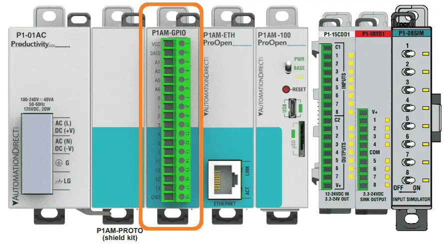
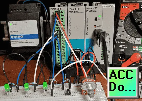
We will be looking at the wiring and programming of this input and output industrial rated shield that mounts on the left side of the P1AM-100 CPU arduino unit.
Analog points will be wired to a potentiometer and LED (light-emitting diode) for demonstration of the voltage range that we can input and output. Digital points will be wired for discrete input and output using a pushbutton switch and LED. PWM (pulse width modulation) will also be used to control the brightness of a LED connected to a digital output. Let’s get started.
Previous posts in this Productivity Open Arduino Compatible Industrial Controller Series
A full list can be obtained at the following location:
Productivity Open (P1AM-100) Arduino Controller
Productivity Open Arduino Controller Hardware
– Starter Kit Unboxing Video
– Powering Up Video
Installing the Software – Video
First Program – Video
Program Structure – Video
Variables Data Types – Video
Serial Monitor COM – Video
Program Control – Video
Operators – Video
Watch the video below to learn about the operation of the P1AM-GPIO on our productivity open industrial arduino controller.
P1AM GPIO Inputs and Outputs General Specification
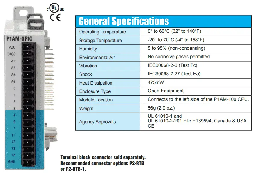
The Arduino P1AM-GPIO is an industrial rated shield that is CSA, UL and CE approved. General specifications are included in the table above.
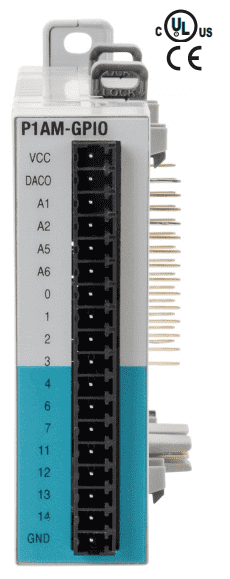
P1AM Arduino GPIO Shield Terminal Block Pin Assignments
The terminal block of the arduino P1AM-GPIO industrial shield (expansion) are connections to the arduino P1AM-100 CPU expansion bus pins.
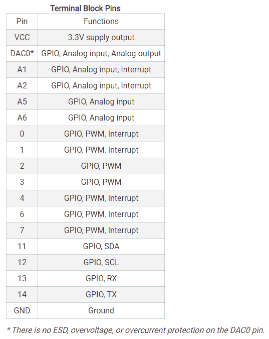
VCC and GND provide the 3.3 VDC supply and 0VDC for our connections.
DAC0 – discrete input or discrete output or Analog input or Analog output (No protection)
A1, A2 – discrete input or discrete output or analog input and/or interrupt function
A5, A6 – discrete input or discrete output or analog inputs
D0, D1 – discrete input or discrete output or PWM output and/or interrupt function
D2, D3 – discrete input or discrete output or PWM output
D4, D6, D7 – discrete input or discrete output or PWM output and/or interrupt function
SCL, SDA – Serial Clock (or SCL), and Serial Data (or SDA). The SCL line is the clock signal which synchronizes the data transfer between the devices on the I2C bus and it’s generated by the master device. SDA line which carries the data. The I2C communication bus is very popular and broadly used by many electronic devices because it can be easily implemented in many electronic designs that require communication between a master and multiple slave devices or even multiple master devices.
TX, RX – Serial communication on pins TX/RX uses TTL logic levels (3.3VDC on the board). Don’t connect these pins directly to an RS232 serial port; they operate at +/- 12V and can damage your arduino board.
Note:
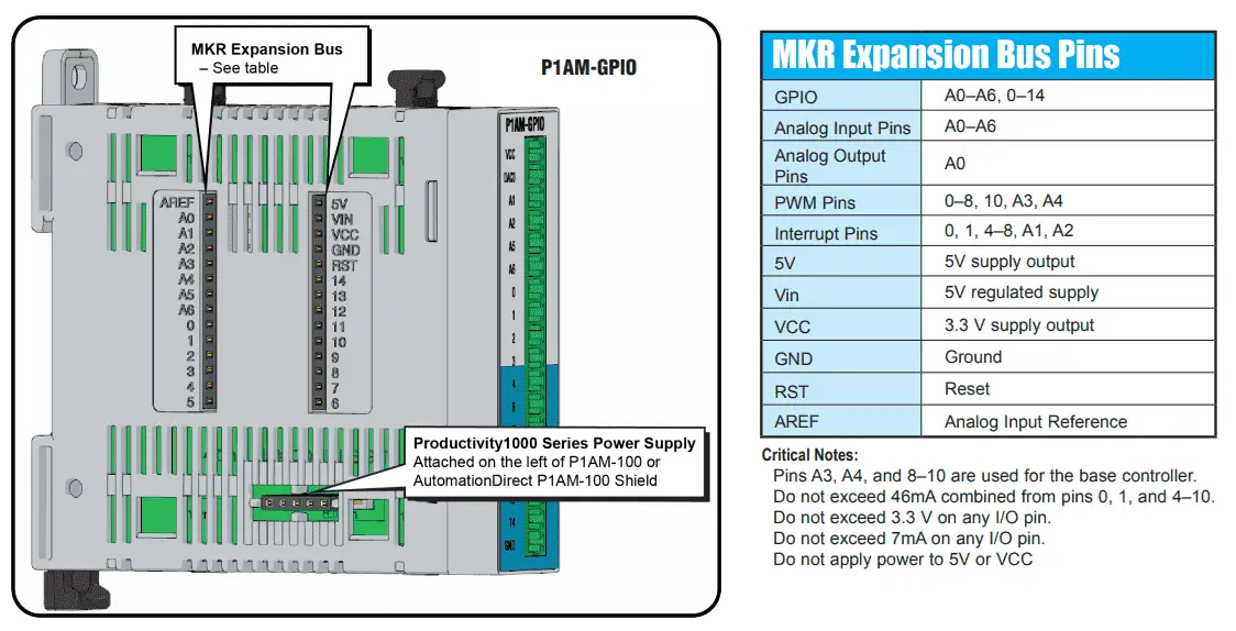
ProductivityOpen MKR-pins extension shield, 0-3.3 VDC. For use with ProductivityOpen P1AM-100 CPU. Requires P2-RTB or P2-RTB-1 removable terminal block or ZIPLink pre-wired cables.
P1AM GPIO Pin Protection Circuit
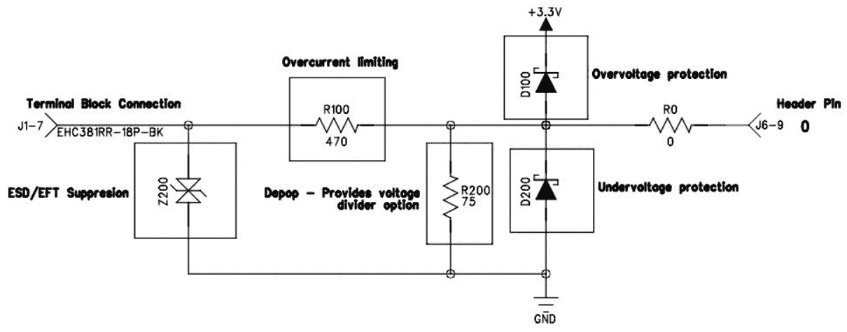
All P1AM GPIO pins except for DAC0 offer some basic electrical protection from temporary faults. These are not guaranteed to protect your device from all failure conditions.
The signal level for the GPIO pins is 3.3VDC.
All GPIO pins (except for DAC0) include basic electrical protection including:
• ESD suppression (electrostatic discharge)
• Overvoltage, and over current protection
• VCC pin includes a PTC (positive temperature coefficient) PolySwitch fuse (Trip – 420mA; Hold – 200mA) – protect against overloading the 3.3VDC supply
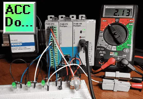
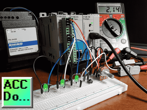
Arduino P1AM GPIO Shield Wiring
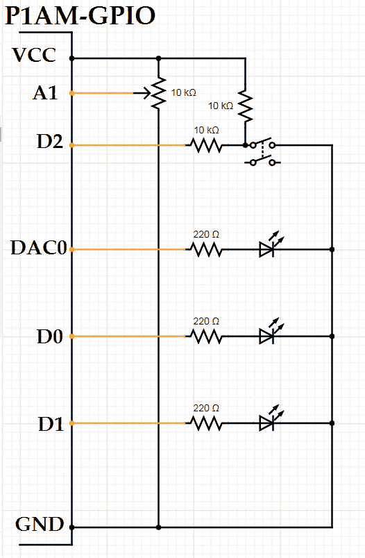
A1 will be an analog input with a 10K ohm potentiometer.
D2 is a digital input that will control the digital output D1. D1 is an LED indicator light that will be either on or off.
DAC0 will be an analog output that will control the intensity of the LED-based upon the input from A1.
D0 will be a PWM output that will also control the intensity of an LED-based upon the input from A1.
PWM (pulse width modulation) will control a digital output during a cycle. A percentage of the on-time versus the off time during each cycle will determine the duty cycle.
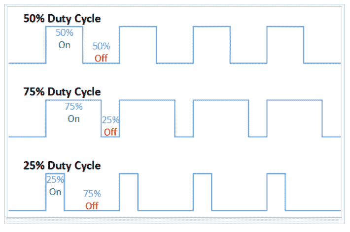
If we measure the PWM output using a voltmeter, then the longer the on-cycle percent the higher the voltage.
Watch the video below to see the operation of our P1AM GPIO inputs and outputs with our productivity open industrial arduino controller.
Sample Program with P1AM Arduino GPIO inputs and outputs
This program will control the Arduino P1AM GPIO as discussed with the wiring above. We will also add the serial monitor when the CPU switch is on to display the analog input signal as a number.
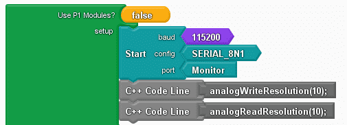
In the setup, we will set our serial monitor and change our analog input and output signals to a 10-bit resolution.
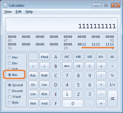
Use the Windows calculator in Programmer mode (View | Programmer) and select Bin (Binary) input to see the resolution of our analog. Enter 1 ten times to show the 10-bit resolution maximum on our input.
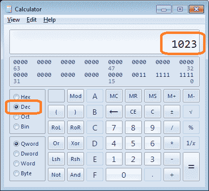
Select the Dec (Decimal) input. This will convert our 10 bits to the number 1023. This means that our resolution will be 1023 steps for our analog signals.
int __ardublockAnalogRead(int pinNumber)
{
pinMode(pinNumber, INPUT);
return analogRead(pinNumber);
}
boolean __ProBlocksDigitalRead(int pinNumber)
{
pinMode(pinNumber, INPUT);
return digitalRead(pinNumber);
}
void __ProBlocksDigitalWrite(int pinNumber, boolean status)
{
pinMode(pinNumber, OUTPUT);
digitalWrite(pinNumber, status);
}
boolean __proBlocksDigitalRead(int pinNumber)
{
pinMode(pinNumber, INPUT);
return digitalRead(pinNumber);
}
void setup()
{
Serial.begin(115200, SERIAL_8N1);
analogWriteResolution(10);
analogReadResolution(10);
}

As part of the loop, we will set A0 and D0 using the Set Analog instruction. The value will come from the analog input from A1. (Potentiometer)
void loop()
{
analogWrite(A0 , __ardublockAnalogRead(A1));
analogWrite(0 , __ardublockAnalogRead(A1));
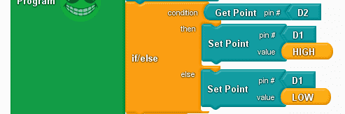
If our digital input from D2 is on then we will set D1 output on. If not then D2 will be off.
if (__ProBlocksDigitalRead(2))
{
__ProBlocksDigitalWrite(1, HIGH);
}
else
{
__ProBlocksDigitalWrite(1, LOW);
}
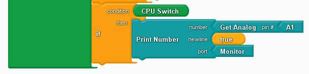
When the P1AM-100 CPU switch is on then send the analog input signal A1 to the monitor so we can view it.
if (__proBlocksDigitalRead(31))
{
Serial.println(__ardublockAnalogRead(A1));
}
}
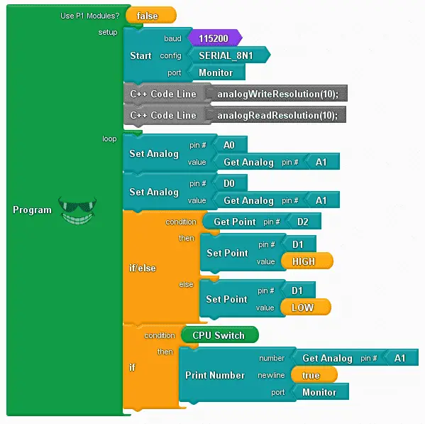
Here is the complete program.
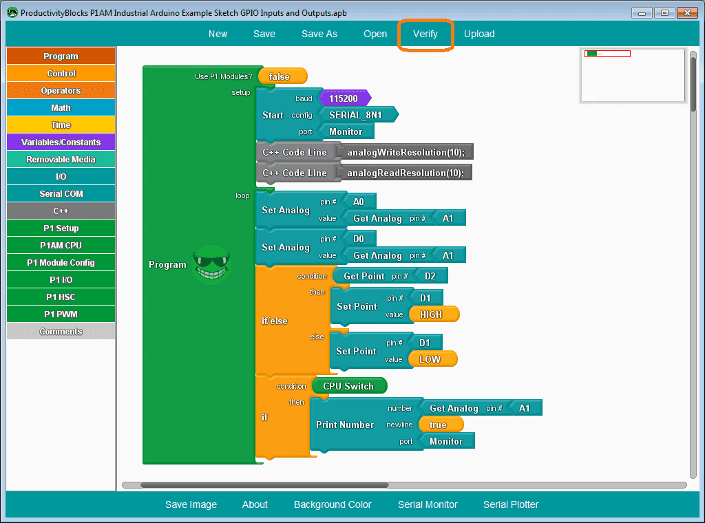
Select verify to compile the code into C++ automatically. ProductivityBlocks save an incredible amount of time with syntax errors and troubleshooting.
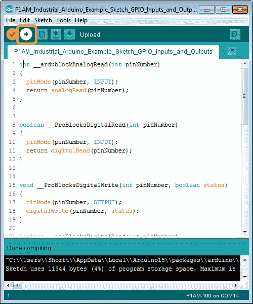
After the compiling is done, select upload on the Arduino IDE.
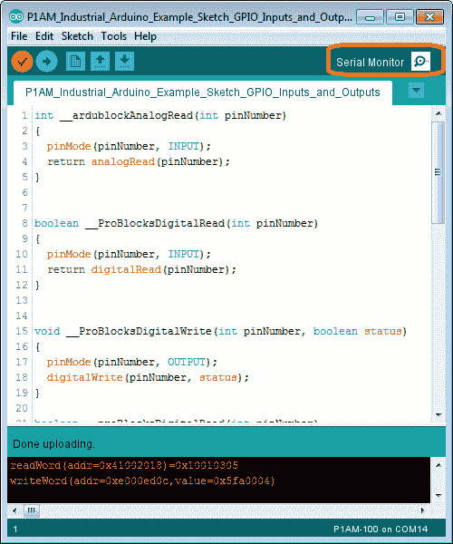
After the uploading to the P1AM CPU is complete then we can select a serial monitor.
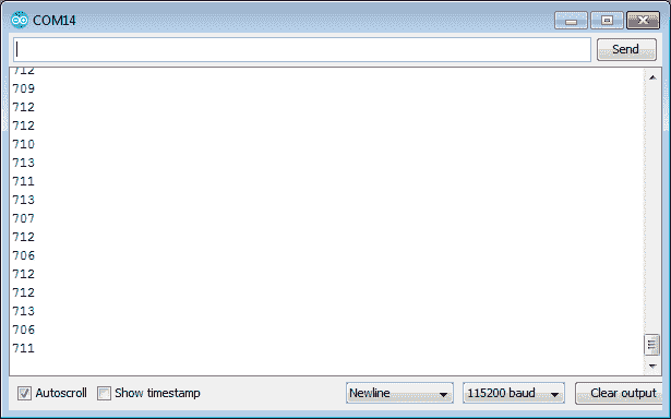
Turn on the CPU switch and we will see the input from the analog input potentiometer.
Watch the video below to see the operation of our program that controls the GPIO inputs and outputs with our productivity open industrial arduino controller.
Download the P1AM-100 sample sketch and Productivity Block program here.
Productivity Open Arduino Compatible Links:
Product Hardware
– Productivity Open (Automation Direct)
– P1AM-100 Specifications
– Productivity Open User Manual
– Configure a Productivity Open Arduino-based Controller
– Open Source Controllers (Arduino-Compatible)
– Productivity Open Documentation (Facts Engineering)
– P1AM Design Files
Software
– Arduino IDE (Integrated Development Environment)
– P1AM-100 library (Easy Interface for controlling P1000 Modules)
– Productivity Blocks (Development Timesaver)
– Productivity Blocks Documentation (Wiki)
Community
– Automation Direct Forum – Open Source Devices
Next time we will look at the math instructions using Productivity Blocks on the P1AM-100 Arduino Industrial Controller.
Watch on YouTube: Productivity Open P1AM Industrial Arduino GPIO Inputs and Outputs
If you have any questions or need further information please contact me. Thank you, Garry
If you’re like most of my readers, you’re committed to learning about technology. Numbering systems used in PLC’s are not difficult to learn and understand. We will walk through the numbering systems used in PLCs. This includes Bits, Decimal, Hexadecimal, ASCII and Floating Point. To get this free article, subscribe to my free email newsletter. Use the information to inform other people how numbering systems work. Sign up now.

The ‘Robust Data Logging for Free’ eBook is also available as a free download. The link is included when you subscribe to ACC Automation.