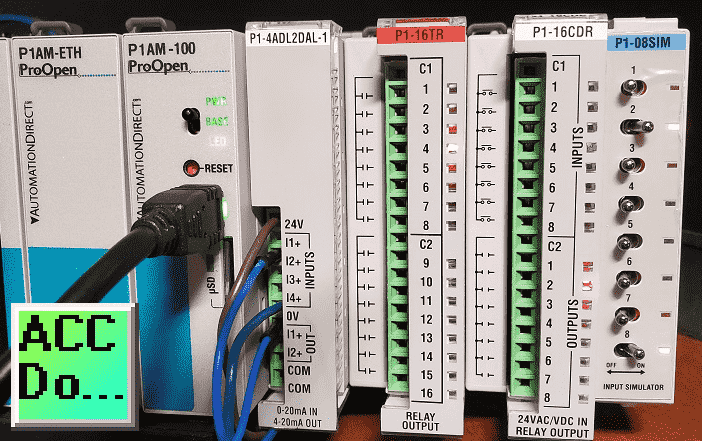
In part 1 we added additional discrete digital inputs and outputs modules (cards) to our P1AM-START1 (Industrial Arduino) ProductivityOpen starter kit with Ethernet. A program was then discussed that will print the modules in our system and then set and reset discrete digital inputs and outputs.
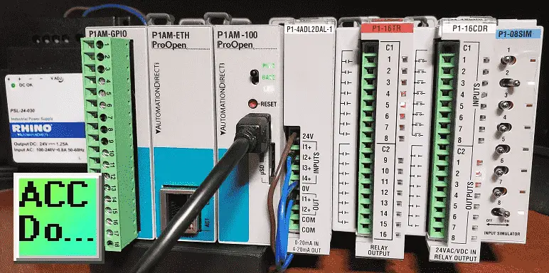
P1-16TR – Productivity1000 relay output module, 16-point, 6-24 VDC/6-120 VAC, (16) Form A (SPST) no-suppression, 2 isolated common(s), 8 point(s) per common, 2A/point, 8A/common.
P1-16CDR – Productivity1000 discrete combo module, Input: 8-point, 24 VAC/VDC, sinking/sourcing, Output: 8-point, 6-24 VDC/6-120 VAC, relay, (8) Form A (SPST) relays, 1A/point.
P1-08SIM – Productivity1000 simulator input module, 8-point.
We will now discuss additional instructions in our industrial Arduino controller that will be used with our P1000 (P1) expansion modules. (cards) Our sample sketch will include a simple start/stop circuit and a shifting circuit.
Let’s get started.
Previous posts in this Productivity Open Arduino Compatible Industrial Controller Series
A full list can be obtained at the following location:
Productivity Open (P1AM-100) Arduino Controller
Productivity Open Arduino Controller Hardware
– Starter Kit Unboxing Video
– Powering Up Video
Installing the Software – Video
First Program – Video
Program Structure – Video
Variables Data Types – Video
Serial Monitor COM – Video
Program Control – Video
Operators – Video
GPIO Inputs and Outputs – Video
Math Instructions – Video
Time Instructions – Video
P1000 Expansion Analog Combination Module – Video
P1000 Expansion Digital Inputs and Outputs Part 1 – Video
Watch the video below to see the program (sketch) using the P1000 discrete input and output modules on our productivity open industrial Arduino controller.
P1 Setup – Roll Call – Digital Inputs and Outputs
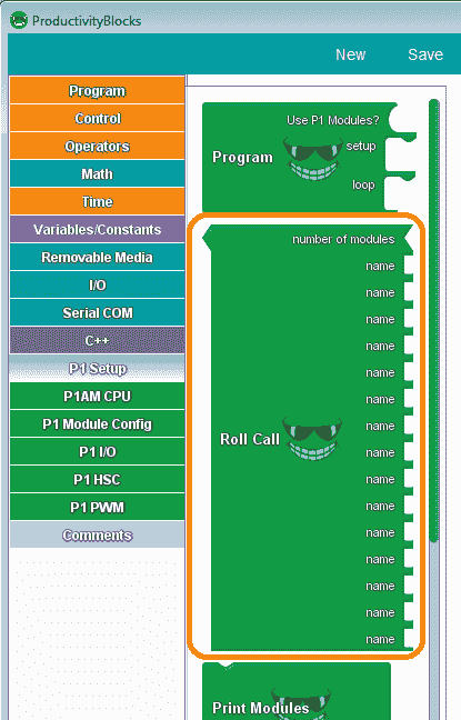
This is a very important instruction block that will Check which P1 Modules were found in P1 Module initialization. Returns the number of Modules that match. This includes our digital input and output cards.
Use this block to check if the P1 modules found in module initialization match the string values in the ‘name’ entries. From top to bottom, each ‘name’ corresponds to the position of the module (from left to right in reference to the P1AM-CPU). The ‘number of modules’ parameter is the number of P1 modules that you are using. The value returned by the ‘Roll Call’ block is the number of module names that match.
Inputs / Outputs Card Addressing (Reference)
The P1000 modules are addressed or referenced by their position to the right-hand side of the industrial Arduino P1AM CPU unit. We can add up to 15 cards (modules) to our CPU unit.
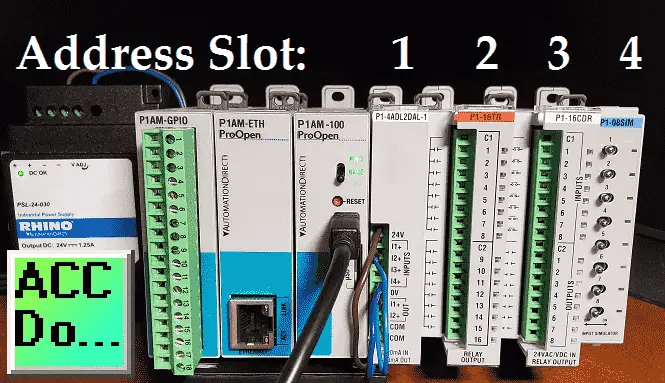
You can see that each of the cards will be numbered from 1 to 15 starting with the closest to the CPU unit being slot number 1. Each digital card may have discrete input and outputs called points. So we can address the individual input or output by the slot and point associated with it.
Masking Inputs
In order to reduce the number of times that we read and write to the digital cards within the same scan of the CPU, we can use masking to look at inputs.
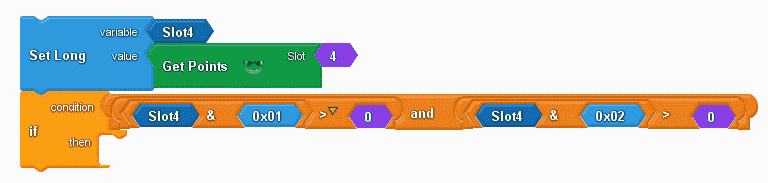
A long variable (Slot4) contains all of the points in slot 4.
Slot4 & 0x01 means that we take all of the inputs AND them with 0000 0001. Anything AND with a 0 is 0. This way we will only look at input 1.
Slot4 & 0x02 means that we take all of the inputs AND them with 0000 0010. Anything AND with a 0 is 0. This way we will only look at input 2.
Our logic above basically states if input 1 is on and input 2 is on then do something.
Example:
1111 1111 – Slot 4
0000 0010 – AND word
0000 0010 – Result (Switch ON)
1101 1101 – Slot 4
0000 0010 – AND word
0000 0000 – Result (Switch OFF)
P1AM Arduino Expansion P1000 Digital Inputs and Outputs Sample Program
Our sample program (sketch) will see if the switch on the CPU is on. The CPU LED will be on if the program is running and off to indicate the outputs are all off. Every scan of the program will check to see if the digital input and output cards are still connected in the order that we have attached them. If they are not then the CPU LED will continually blink (flash) and all of the outputs will remain off.
When the program is running we will make a simple start-stop circuit.
A shift register will also be used to turn on output on the P1-16TR (16 relay output card) in sequence. Point 1 to 16 and then 16 to 1 at 500-millisecond increments.
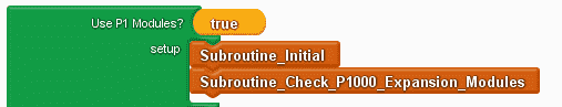
The use of P1 Modules is set to true. This will include the library for the P1AM and P1_HSC. We set up the subroutines that will be called.
Subroutine_Initial will turn off our outputs and initialize our timing variable for the shift register.
Subroutine_Check_P1000_Expansion_Modules will check to ensure that the digital cards are still attached and functioning correctly.
#include
#include

/******************************************************************************************
* Automationdirect.com
* This version of ProductivityBlocks supports P1AM-100 Library V1.0.0
* To download this library, please visit https://github.com/facts-engineering/P1AM
* For information on the P1AM-100 hardware, please visit https://www.automationdirect.com
******************************************************************************************/
const char* _PBVAR_5_RollCall[] = {
"P1-4ADL2DAL-1", "P1-16TR", "P1-16CDR", "P1-08SIM", "P1-", "P1-", "P1-", "P1-", "P1-", "P1-", "P1-", "P1-", "P1-", "P1-", "P1-"};
#define _PBVAR_6_CPU_LED_PIN 32
boolean __proBlocksDigitalRead(int pinNumber)
{
pinMode(pinNumber, INPUT);
return digitalRead(pinNumber);
}
void __proBlocksDigitalWrite(int pinNumber, boolean status)
{
pinMode(pinNumber, OUTPUT);
digitalWrite(pinNumber, status);
}
unsigned long _PBVAR_1_Slot4 = 0UL ;
int _PBVAR_2_Shift_Register = 0 ;
bool _PBVAR_3_Shift_Left= false ;
int _PBVAR_4_previousMillisecond = 0 ;
void Subroutine_Initial();
void Subroutine_Check_P1000_Expansion_Modules();
void setup()
{
while(!P1.init())
{
}
Subroutine_Initial();
Subroutine_Check_P1000_Expansion_Modules();
}

We use an if/else condition of the CPU switch. If on then we turn on the CPU LED and then set a long variable (Slot4) with the value from the get points instruction. This will tell us the position of each switch on our input simulator.
void loop()
{
if (__proBlocksDigitalRead(31))
{
__proBlocksDigitalWrite(32, HIGH);
_PBVAR_1_Slot4 = P1.readDiscrete(4, 0) ;

This is the simple start-stop circuit of our program. Slot 4 point 1 is our start and slot 4 point 2 is our stop. We use the AND instruction with the slot4 variable to determine the status of each of the inputs. When input 1 and input 2 are on then we will set slot 3 point 2 on. (start) If slot 4 point 2 turns off then we set slot 3 point 2 off. (stop)
//Start / Stop Circuit - Switch 1 Start / Switch 2 Stop (NC)
if (( ( ( (_PBVAR_1_Slot4 & 0x01UL) ) > ( 0 ) ) && ( ( (_PBVAR_1_Slot4 & 0x02UL) ) > ( 0 ) ) ))
{
P1.writeDiscrete( (uint32_t)HIGH, 3, 2);
}
if (( ( (_PBVAR_1_Slot4 & 0x02UL) ) == ( 0 ) ))
{
P1.writeDiscrete( (uint32_t)LOW, 3, 2);
}
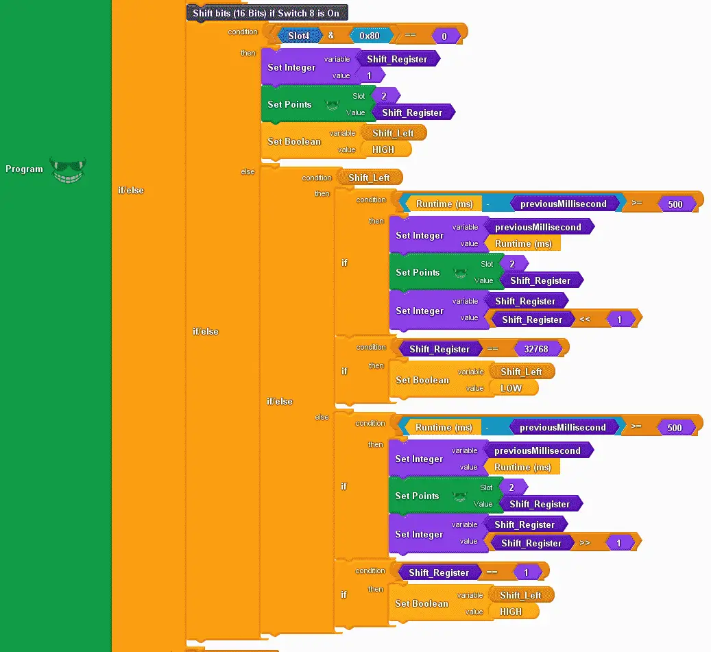
This is the shift register instruction. Using an if/else instruction we use the condition of slot 4 point 8. (0x80 = 1000 0000) If it is off, (equal to 0) then we will set the shift register variable to the value of 1. We then set slot 2 with the shift register variable. This will reset our output card. We also set a Boolean variable called shift left to high. This will keep track to see if we are shifting left or right.
When input slot 4 point 8 is on we will then use another if/else instruction. This checks for the condition of the variable shift left.
If on then we see if enough time (500 ms) has passed to shift the shift register left. We then set the output points and shift the shift register variable left by 1. We determine if the last bit of the shift register variable is on. (32768) If it is equal to this value, we then set the shift left variable to off. This will enable shifting to the right.
If off then we see if enough time (500 ms) has passed to shift the shift register right. We then set the output points and shift the shift register variable right by 1. We determine if the first bit of the shift register variable is on. (1) If it is equal to this value, we then set the shift left variable to on. This will enable shifting to the left again.
//Shift bits (16 Bits) if Switch 8 is On
if (( ( (_PBVAR_1_Slot4 & 0x80UL) ) == ( 0 ) ))
{
_PBVAR_2_Shift_Register = 1 ;
P1.writeDiscrete(_PBVAR_2_Shift_Register, 2, 0);
_PBVAR_3_Shift_Left = HIGH ;
}
else
{
if (_PBVAR_3_Shift_Left)
{
if (( ( ( millis() - _PBVAR_4_previousMillisecond ) ) >= ( 500 ) ))
{
_PBVAR_4_previousMillisecond = millis() ;
P1.writeDiscrete(_PBVAR_2_Shift_Register, 2, 0);
_PBVAR_2_Shift_Register = (_PBVAR_2_Shift_Register << 1) ;
}
if (( ( _PBVAR_2_Shift_Register ) == ( 32768 ) ))
{
_PBVAR_3_Shift_Left = LOW ;
}
}
else
{
if (( ( ( millis() - _PBVAR_4_previousMillisecond ) ) >= ( 500 ) ))
{
_PBVAR_4_previousMillisecond = millis() ;
P1.writeDiscrete(_PBVAR_2_Shift_Register, 2, 0);
_PBVAR_2_Shift_Register = (_PBVAR_2_Shift_Register >> 1) ;
}
if (( ( _PBVAR_2_Shift_Register ) == ( 1 ) ))
{
_PBVAR_3_Shift_Left = HIGH ;
}
}
}
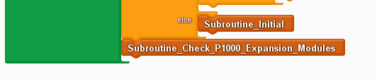
If the CPU switch is off, we call the subroutine initial. At the end of every loop, we call the subroutine to check P1000 expansion modules.
}
else
{
Subroutine_Initial();
}
Subroutine_Check_P1000_Expansion_Modules();
}
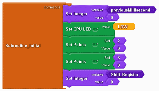
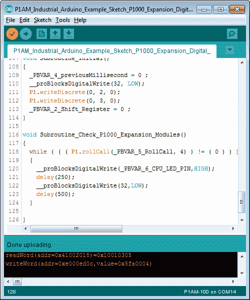
Subroutine initial will set our previous milliseconds to a value of 0, set the CPU LED low (off), and set all of the digital output points off on our Arduino P1AM. The shift register variable is also set to 0.
void Subroutine_Initial()
{
_PBVAR_4_previousMillisecond = 0 ;
__proBlocksDigitalWrite(32, LOW);
P1.writeDiscrete(0, 2, 0);
P1.writeDiscrete(0, 3, 0);
_PBVAR_2_Shift_Register = 0 ;
}
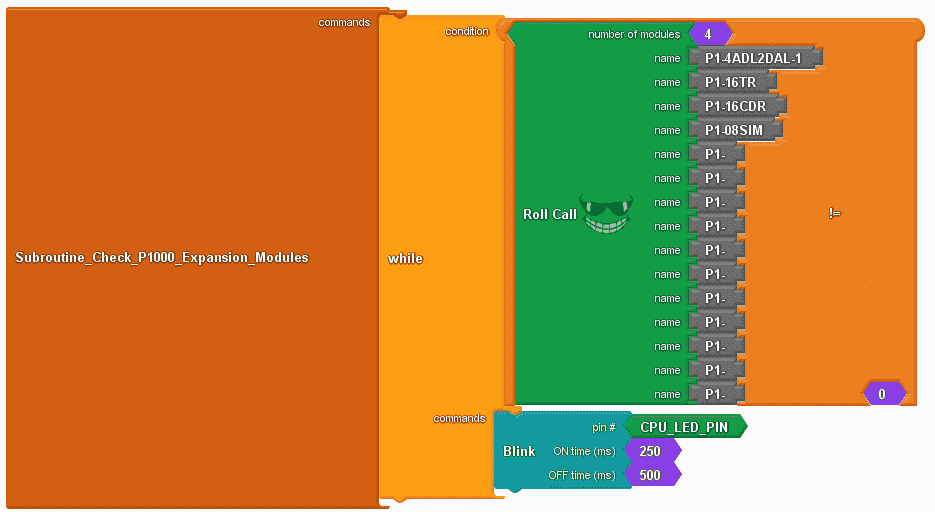
Subroutine check P1000 expansion modules will use the roll call instruction. While the roll call instruction is not equal to 0 (modules do not match) then blink the CPU LED light.
void Subroutine_Check_P1000_Expansion_Modules()
{
while ( ( ( P1.rollCall(_PBVAR_5_RollCall, 4) ) != ( 0 ) ) )
{
__proBlocksDigitalWrite(_PBVAR_6_CPU_LED_PIN,HIGH);
delay(250);
__proBlocksDigitalWrite(32,LOW);
delay(500);
}
}
Once the upload to the P1AM CPU is complete, we can test our digital inputs and outputs arduino program.
When the CPU switch is on will see our start-stop circuit and shift register program working. Disconnect a module and see the flashing CPU LED.
Note: Do not disconnect the P1000 expansion modules with power on.
Watch the video below to see the operation of our sample sketch with the productivity open industrial Arduino controller digital IO.
Download the P1AM-100 sample sketch and Productivity Block program here.
Productivity Open Arduino Compatible Links:
Product Hardware
– Productivity Open (Automation Direct)
– P1AM-100 Specifications
– Productivity Open User Manual
– Configure a Productivity Open Arduino-based Controller
– Open Source Controllers (Arduino-Compatible)
– Productivity Open Documentation (Facts Engineering)
– P1AM Design Files
Software
– Arduino IDE (Integrated Development Environment)
– P1AM-100 library (Easy Interface for controlling P1000 Modules)
– Productivity Blocks (Development Timesaver)
– Productivity Blocks Documentation (Wiki)
Community
– Automation Direct Forum – Open Source Devices
Next time we will look at the watchdog on our P1AM-100 Arduino Industrial Controller.
Watch on YouTube: Productivity Open P1AM Industrial Arduino P1000 Expansion Digital Inputs and Outputs Part 2
If you have any questions or need further information please contact me.
Thank you, Garry
If you’re like most of my readers, you’re committed to learning about technology. Numbering systems used in PLC’s are not difficult to learn and understand. We will walk through the numbering systems used in PLCs. This includes Bits, Decimal, Hexadecimal, ASCII and Floating Point. To get this free article, subscribe to my free email newsletter. Use the information to inform other people how numbering systems work. Sign up now.

The ‘Robust Data Logging for Free’ eBook is also available as a free download. The link is included when you subscribe to ACC Automation.