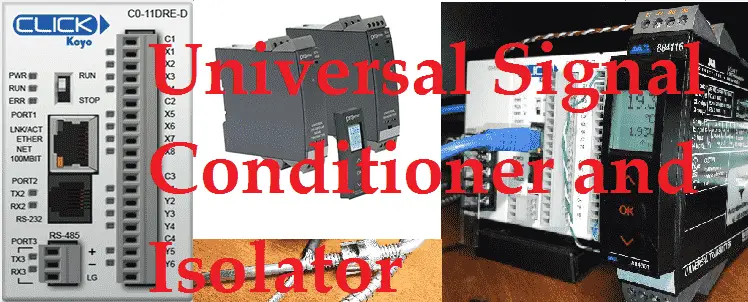
Signal conditioners are used with analog current and voltage signals. They have the ability to change your input analog signal to another output analog signal. As an example, we can have 4-20mA analog input and change it to a 0-10VDC output signal so we can wire this into our PLC. Typically signal conditioners will also electrically isolate the input and output signals. This is either done by magnetic or optical isolation. You would usually specify the input and output signals that are required in your circuit to choose the signal conditioner required. Using a universal signal conditioner will take a variety of signals and is a great product to use in troubleshooting analog circuits.
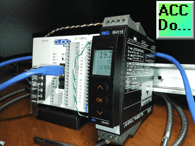
We will be using a universal signal conditioner to convert a thermocouple temperature input into a 0-10VDC linear output. This will be wired into the analog card of the Click PLC.
Let’s get started.
Additional component connections to PLC include the following:
Here’s a Quick Way to Wire NPN and PNP Devices
– Wiring NPN Sensor to PLC Video
– Wiring PNP Sensor to PLC Video
– Wiring Contact Discrete PLC Inputs Video
Wiring Interposing Relays
– Wiring NPN and PNP Sensors into the PLC with an Interposing Relay Video
Click PLC HMI Rotary Encoder Dial Input – Video
Wiring Stack Light to Click PLC – Video
Wiring Push Buttons and Selector Switch to Click PLC – Video
– Test and Assembly of Push Buttons and a Selector Switch – Video
Wiring an Inductive Proximity NPN PNP Sensor to the Click PLC – Video
Wiring a Capacitive Proximity NPN PNP Sensor to the Click PLC – Video
Wiring an Ultrasonic Proximity Sensor to the Click PLC – Video
– Unboxing our UK1F Ultrasonic Proximity Sensor – Video
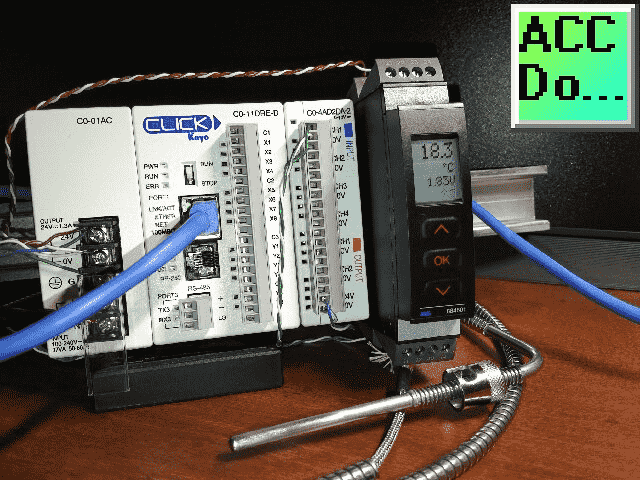
Watch the video below to see the wiring and operation of our Universal Signal Conditioner and Isolator to the Click PLC.
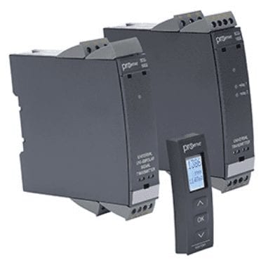
Universal Input Signal Conditioners / Signal Isolators
Signal Conditioners
You can purchase dedicated signal conditions that specify the input and output configuration. These would be ideal for specific applications. The universal input signal conditioner is a great device to have for troubleshooting any existing analog circuits. You can use it as the isolator for the input signal.
Universal Input Signal Conditioners
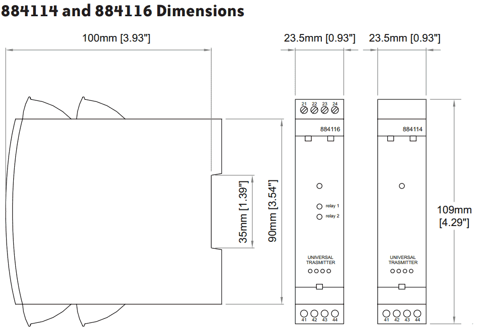
The device we will be using is an 884116 but this has been replaced with the improved SCU-1600 which also has Factory Mutual (FM) approval for hazardous locations and lower investment. All of the programming and dimensions are the same for the two units.
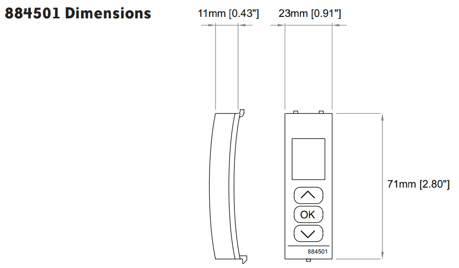
A detachable programming/display module will be used on our device. (884501) This has been replaced with the SCU-PDM1 that will program the SCU series.
The following is the selection of universal signal conditioner types.
- SCU-1400 – mA or VDC analog output
- SCU-1600 – mA or VDC analog output, 2 relay outputs
- SCU-3100 – 2 relay outputs … New!
- SCU-8400 – unipolar and bipolar input signals … New!
- SCU-7900 – AC RMS current or voltage input … New!
Terminology
Linearization – This is when the actual input does not have a direct relationship to the actual measurement. The output can be made linear to make it more of a direct relationship. An example of this would be for thermocouple inputs.
Amplifying – This is the process of increasing the resolution of the input signal or increasing the signal to noise ratio. A small gain on the input side from 1 to 1.2VDC can relate to a 1 to 2.4VDC on the output as an example. Note: the signal can also be reversed and you can get less resolution.
Filtering – This is automatically built into the signal conditioner. If we look at the response time of the conditioner, this will play a part of our filtering circuit.
Specifications for the 884116
Dimensions
Wiring Diagrams
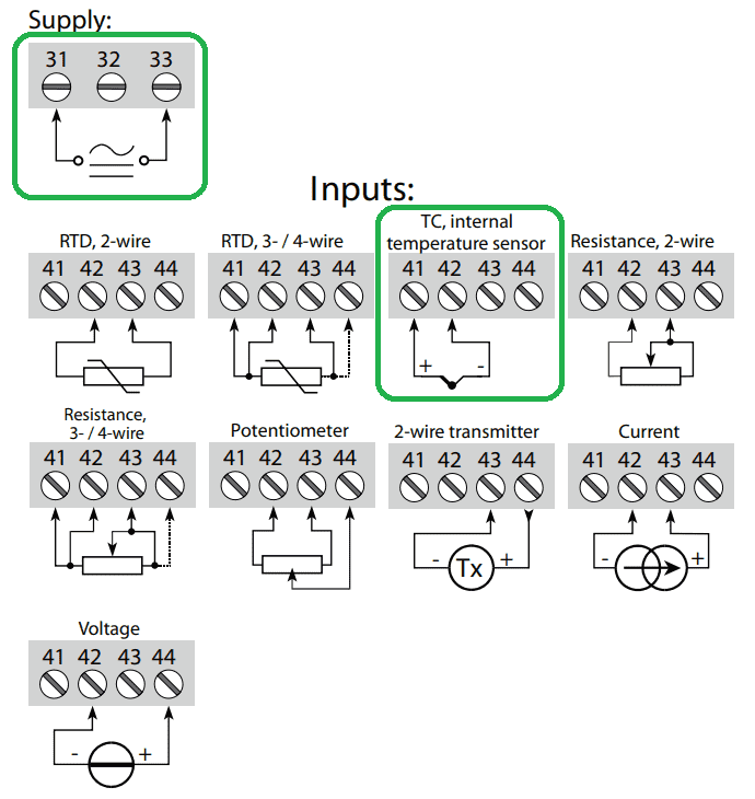
We will be powering up our signal conditioner with 24VDC. You can see that it does not matter the way in which the supply is given.
Our device can be powered with any of the following:
AC Power – 21.6 to 253 VAC 50/60Hz
DC Power – 19.2 to 300 VDC
Note: There is an auxiliary power supply output rated at 16 – 25 VDC, 20mA maximum. (Terminal 43 and 44) This can be used to power sensors.
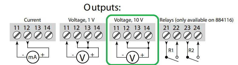
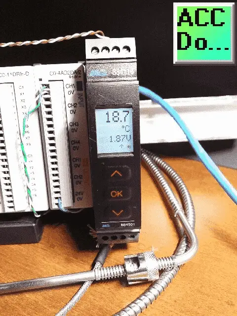
Our output will be 0- 10VDC. Note the jumper that is needed between pin 12 and 14.
Programming Universal Signal Conditioner and Isolator
All programming is done with a programming module that will mount on the front of the unit. If no sensor is connected to the input terminals, SE.BR (Sensor Break) will flash on the display when the unit is powered up. Press OK once to acknowledge the error and then press OK again to display the first screen of the menu.
OK, button – This will confirm the selection shown on the screen and move to the next step.
UP/Down arrows – These buttons will scroll through options on each step.
Thermocouple Input Example
In the configuration, menu press the up/down arrows until TEMP is displayed on line 1. Press OK.
Select sensor type. Press up/down arrows until TC is displayed for SENSOR. Press OK.
Select TC type. Press up/down arrows until TC.J is displayed for TC.TYPE. Press OK.
Select temperature units. Press up/down arrows until degree C is displayed for UNIT. Press OK.
Our unit has two relays outputs that we will leave in the OFF state. Press OK when the unit displays R1.FUNC and R2.FUNC.
Select the output mode. Press up/down arrows until VOLT is displayed for ANA.OUT. Press OK.
Select the output range. Press up/down arrows until 0-10 is displayed for O.RANGE. Press OK.
Set temperature for analog output low. Press up/down arrows until 0.0 is displayed for OUT.LO. Press OK.
Set temperature for analog output high. Press up/down arrows until 100.0 is displayed for OUT.HI. Press OK.
Wait while the settings are stored and the unit switches to run mode.
We have now programmed out universal signal conditioner.
Click PLC Program – Analog Input Signal Converter and Isolator
The first thing that we will do is set up our analog input card to scale the 0-10VDC signal to 0.0 to 100.0 degrees Celsius. Call up the system configuration from the main menu | Setup | System Configuration… Alternatively, you can also use the System Configuration selection under the Function tab in the Navigation window.
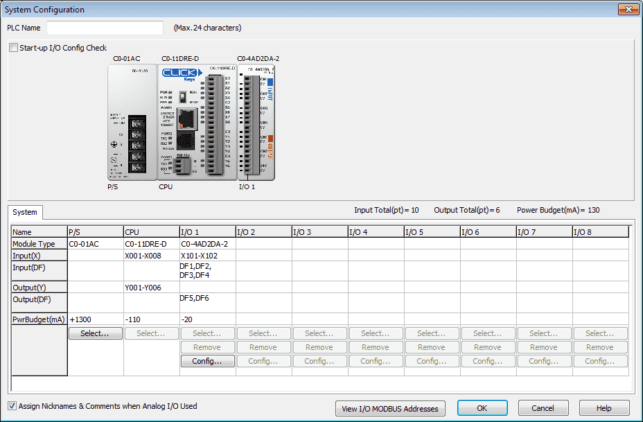
Select Config…
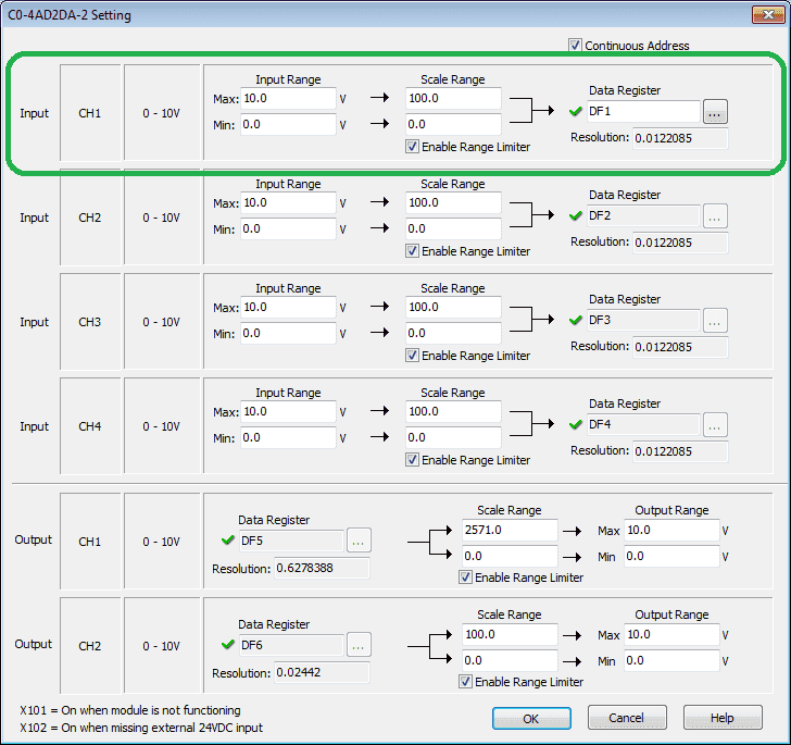
We will use CH1 for our analog input. Input range 10.0 to 0.0 will correspond to Scale range 100.0 to 0.0. The values will be read in data register DF1.
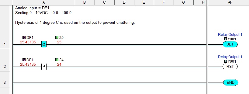
We will use a simple program in our Click PLC. When DF1 is greater than or equal to 25 degrees Celsius we will set (latch) output Y1. When DF1 is less than or equal to 24 we will reset (unlatch) Y1. This will create a hysteresis of 1 degree so that our output will not chatter.
Monitoring the Click PLC Analog Input and Output
If the PLC is in a panel and you cannot see the actual inputs and outputs (IO) there is a way to see the status lights. System Monitor is used to doing just that through the Click PLC software.
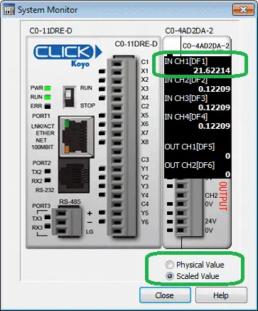
System Monitor can be accessed through the main menu | Monitor | System Monitor…
As we run our program the status of the PLC can be monitored.
You can see that we can monitor the physical value of analog CH1 (0-10VDC) or the Scaled value of CH1 (0.0 – 100.0 degrees).
Please watch the video below to see the wiring and operation of the universal transmitter to our Click PLC analog input.
Download the Click PLC program here.
Universal Signal Conditioner Manuals, Product Inserts / Quick Start Guides
Universal Signal Conditioners Features
– Universal supply voltage, 21.6 to 253 VAC or 19.2 to 300 VDC, polarity insensitive
– 3-way isolation between input, output, and power
– Easy-to-use detachable LCD programming/display module SCU-PDM1 (sold separately, required for programming)
– Transfer configuration settings from one signal conditioner to another with SCU-PDM1
– Integral 35mm DIN rail mounting adapter
– Removable screw terminal blocks are keyed to ensure correct installation
– 5-year warranty
Watch on YouTube: Universal Signal Conditioner and Isolator
Here is some additional information on wiring PLC inputs.
Wiring NPN Sensor to PLC
https://youtu.be/Z09l3HKMpqs
https://accautomation.ca/heres-a-quick-way-to-wire-npn-and-pnp-devices/
Wiring PNP Sensor to PLC
https://youtu.be/nP33k5e_Y-k
https://accautomation.ca/heres-a-quick-way-to-wire-npn-and-pnp-devices/
Wiring Contact Discrete PLC Inputs
https://www.youtube.com/watch?v=xh5dE2Z09d0
https://accautomation.ca/how-plc-inputs-work/
Wiring Stack Light to Click PLC
https://accautomation.ca/wiring-stack-light-to-click-plc/
https://youtu.be/gwDIVtNSXfs
If you have any questions or need further information please contact me.
Thank you,
Garry
If you’re like most of my readers, you’re committed to learning about technology. Numbering systems used in PLC’s are not difficult to learn and understand. We will walk through the numbering systems used in PLCs. This includes Bits, Decimal, Hexadecimal, ASCII and Floating Point.
To get this free article, subscribe to my free email newsletter.
Use the information to inform other people how numbering systems work. Sign up now.

The ‘Robust Data Logging for Free’ eBook is also available as a free download. The link is included when you subscribe to ACC Automation.