ACC PLC Simulator – How to Use the Free Browser-Based PLC Trainer
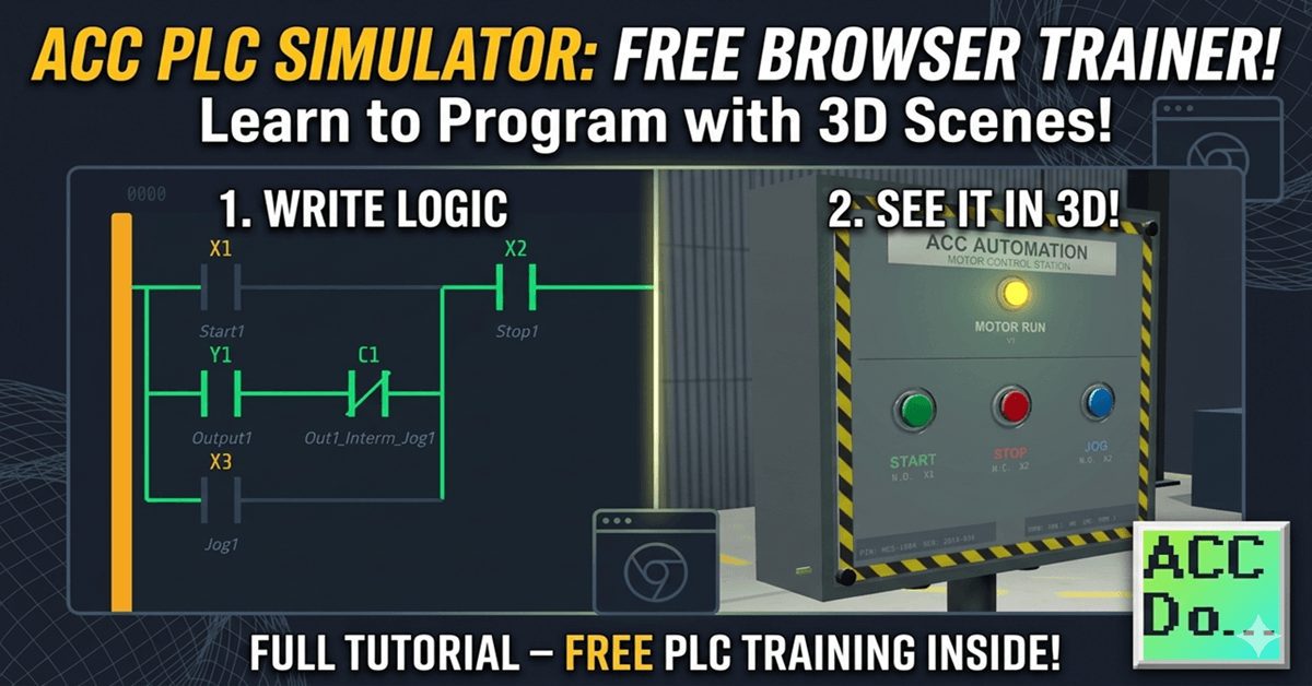
The ACC PLC Simulator is a free, browser-based ladder-logic editor and PLC scan engine. There is nothing to download or install. You open it in Chrome, Edge, or Firefox and start programming immediately. I built this simulator so that anyone learning PLC programming can get hands-on practice without needing hardware. It uses standard PLC register … Read more