
We will now look at the compare instructions available on the Omron CP1H controller. Just about every program usually has some data comparison instruction. This is the ability to compare information from one area of the controller to another and act on results. The Omron CP1H series of programmable logic controllers provide several different ways to compare the information. We will be looking at several different ways in which we can do this with some programming examples. Sometimes the instruction used for data comparison in the Omron CP1H will determine the kind of data that we are comparing. You must look at the individual instructions to determine if this is the case or not.
Previously in this CP1H series, we have discussed:
System Hardware – Video
CX-Programmer – Video
Establish Communication – Video
Setting, Forcing and Online Editing – Video
Numbering System and Addressing – Video
CP1H Timers – Video
Counters – Video
Data Movement – Video
Compare Instructions – Video
Data Shift Instructions
– Video Part 1
– Video Part 2
Math Instructions – Video
Data Conversion – Video
Program Control Instructions – Video
Table Data Instructions – Video
Data Control Instructions – Video
AdvancedHMI Communication – Video
We will be covering several different data comparison instructions. A full explanation can be obtained by using the help menu in the CX-Programmer software or the Programming Manual for the CP1H. Links are provided at the end of this post.
Several of the instructions can have different variations.
Let’s look at a couple of instructions:
MCMP(019) when used will be scanned and executed every cycle of the PLC that the input condition is on.
@MCMP(019) when used will be executed when the input condition turns from off to on. This will trigger the instruction to happen only once.
!CMP(020) when used will do an immediate refreshing of the information before the data compare takes place on every scan.
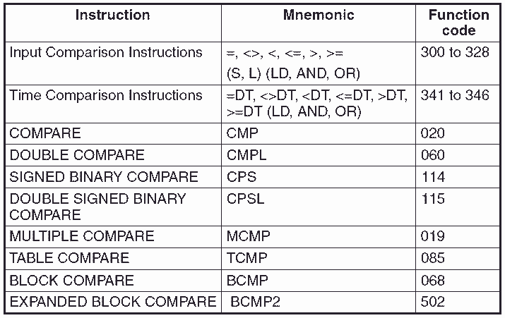
Please refer to the programming manual or help file in CX-Programmer for different variations of the instructions that you want to use. We will now quickly go over the data comparison instructions in the Omron CP1H.
Input Comparison Instructions (300 to 328) – Omron CP1H
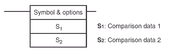
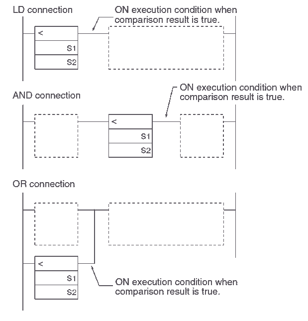
Input comparison instructions will compare two values and create an ON execution condition when the comparison condition is true. These instructions are used as input conditions on the ladder logic rung.
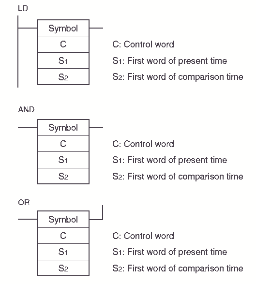
Depending on the location within the rung, these instructions can be used as a ‘LD’, ‘AND’ or ‘OR’ condition.
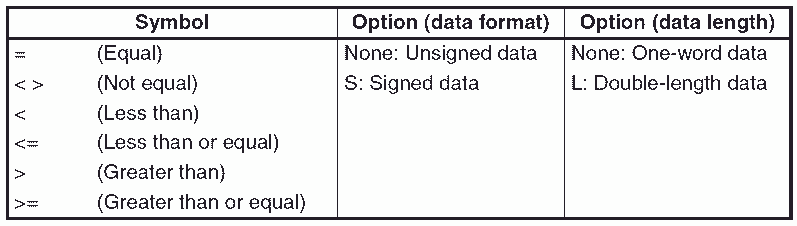
Optional information can also be used to indicate data format and data length.
Internal flags are also set when the instruction executes.

Here is an example:
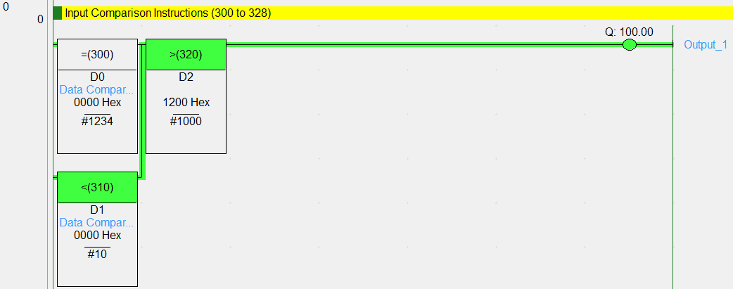
When memory area D0 is equal to #1234 or D1 is less than #10 and D2 is greater than #1000 then turn on output 100.00.
Time Comparison Instructions (341 to 346) – Real-Time Clock – Omron CP1H
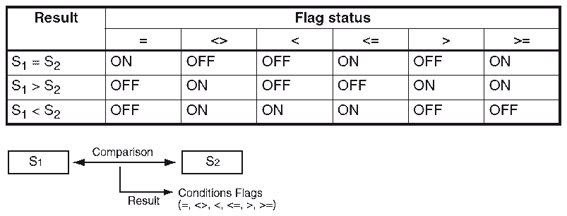
Time comparison instructions will compare two BCD time values and create an ON execution condition when the comparison condition is true. These instructions are used as input conditions on the ladder logic rung and are similar to the input comparison instructions discussed above.
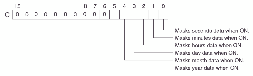
The instructions have a control word that is used to mask elements that you do not want to compare. Mask means to cover up and not use when doing a compare.
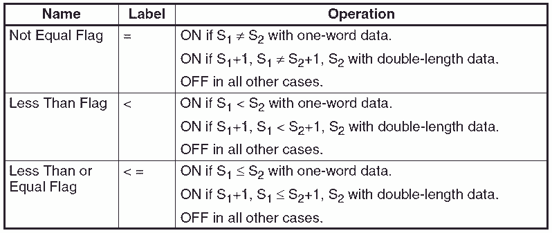
Here are the flag conditions when the time comparison instructions are used.
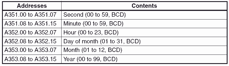
The location for the real-time clock values is located in the following memory area.
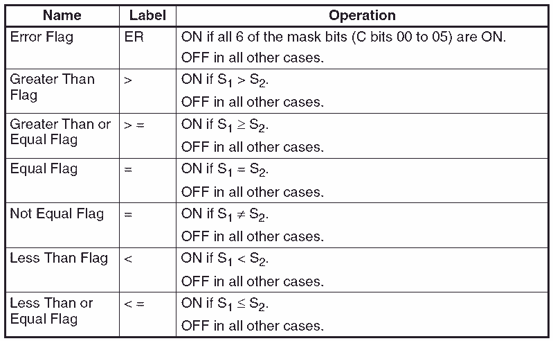
An error flag will be set if all of the masks are set in the control word.
Here is an example:
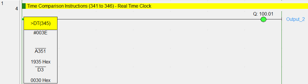
Our control word is set for #003E which will mask everything except for the seconds of the real-time clock. If the real-time clock seconds (A351) is greater than 30 then output 100.01 will then turn on.
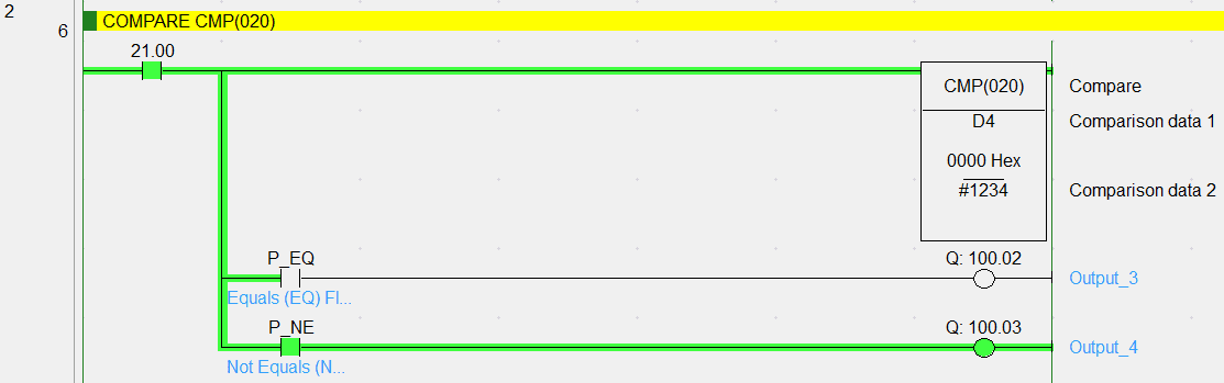
COMPARE CMP(020) – Omron CP1H
This instruction will compare two unsigned binary values and outputs the result to the flags in the auxiliary area.

In the following example, once the compare instruction has been executed it will set the internal flag bits. These bits must then be used immediately after the instruction because other instructions may also set them.
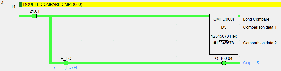
DOUBLE COMPARE CMPL(060) – Omron CP1H
This instruction will compare two double unsigned binary values and outputs the result to the flags in the auxiliary area.

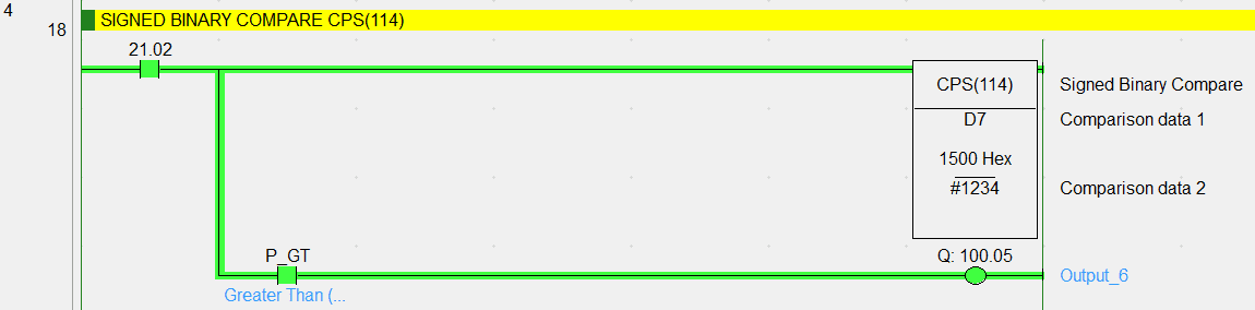
SIGNED BINARY COMPARE CPS(114) – Omron CP1H
This instruction will compare two signed binary values and outputs the result to the flags in the auxiliary area.
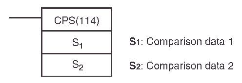
The instruction indicates the type of data that is being compared. In signed binary we can represent negative numbers.
See What Everybody Ought to Know About Numbering Systems for a good reference on signed binary.
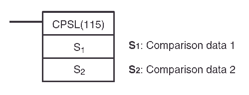
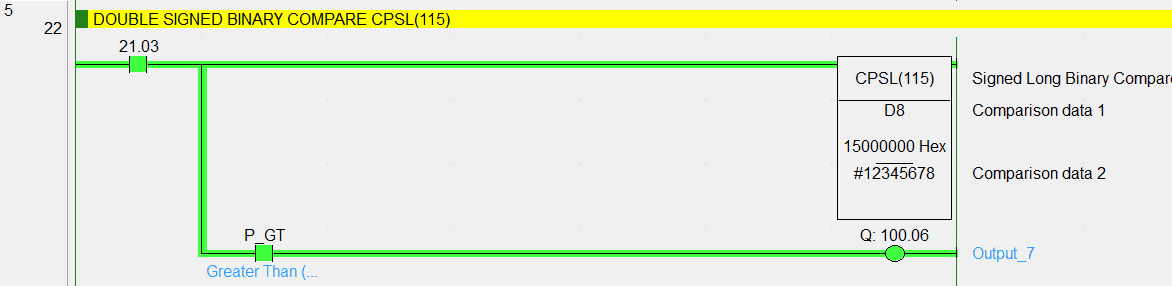
DOUBLE SIGNED BINARY COMPARE CPSL(115) – Omron CP1H
This instruction will compare two double signed binary values and outputs the result to the flags in the auxiliary area.
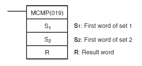
MULTIPLE COMPARE MCMP(019) – Omron CP1H
This instruction will compare 16 consecutive words with another 16 consecutive words and sets the corresponding bit in the result word. (16 bits)
The following chart will show you the comparisons:

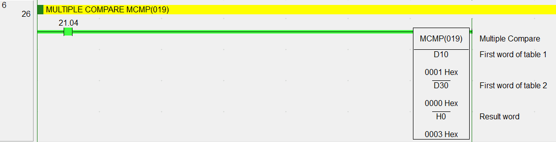
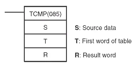
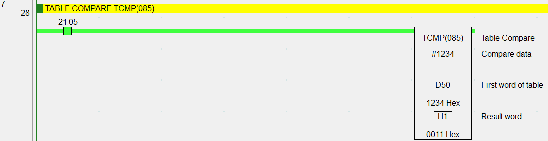
TABLE COMPARE TCMP(085) – Omron CP1H
This instruction will compare a single source word with another 16 consecutive words and sets the corresponding bit in the result word. (16 bits)
The following chart will show you the comparisons:

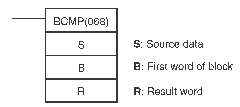
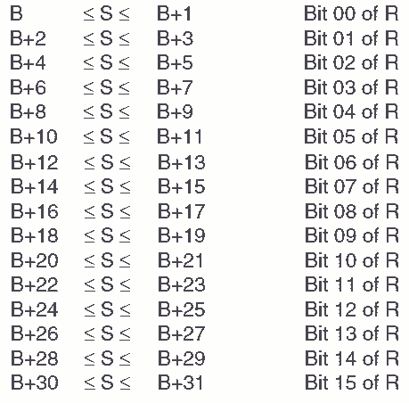
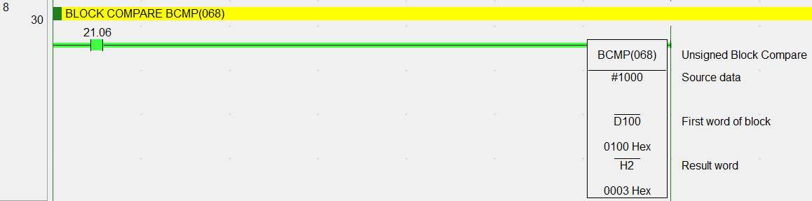
BLOCK COMPARE BCMP(068) – Omron CP1H
Compares the source word to 16 ranges and turns on the corresponding bit in the result word. (16 bits) The ranges are defined by 16 lower limits and 16 upper limits.
Here is the chart that shows the consecutive range limits.
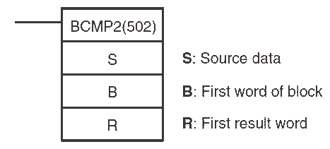
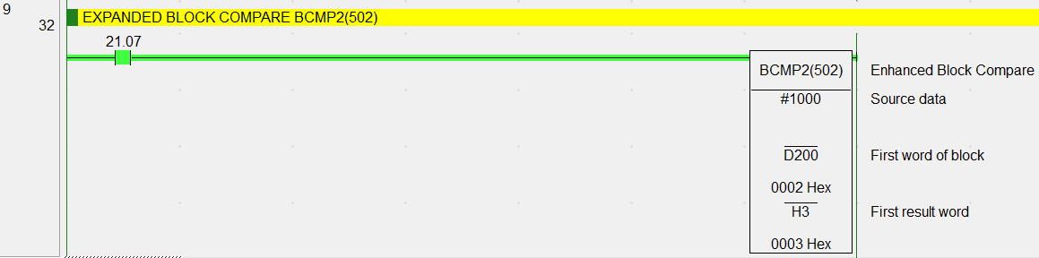
EXPANDED BLOCK COMPARE BCMP2(502) – Omron CP1H
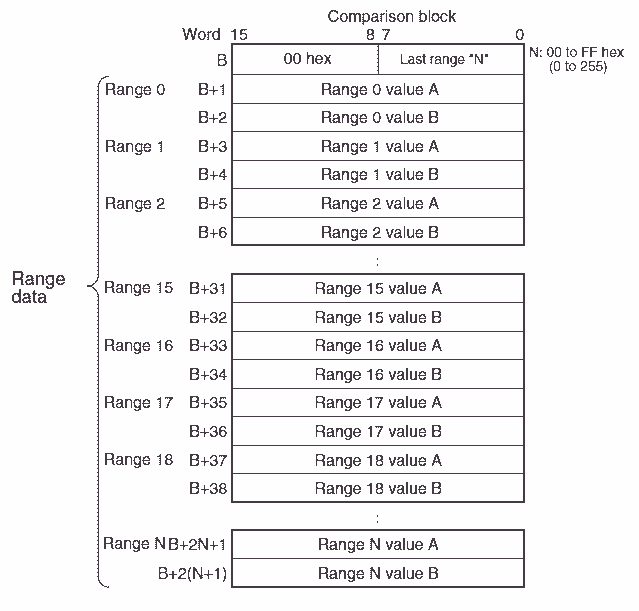
Compares the source word up to 256 ranges and turns on the corresponding bit in the result word. The ranges are defined by 256 lower limits and 256 upper limits.
The comparison block will contain the number of ranges in the first word. Here is a chart showing the relationships.
There are other data comparison instructions in the CP1H. The instructions like Area Range Compare and Double Area Range Compare can be found in the operation manual or in the CX programmer help file.
You can see that we have many different instructions to compare data in the Omron CP1H. This should give you a good idea of what is possible.
See the YouTube video below on data comparison in the Omron CP1H PLC.
The following is a list of manuals associated with the CP1H programmable logic controller. See the descriptions for each of these manuals in the first post: Omron CP1H System Hardware
W450 – SYSMAC CP Series CP1H CPU Unit Operation Manual
W451 – SYSMAC CP Series CP1H CPU Unit Programming Manual
W342 – SYSMAC CS/CJ series Communications Commands Reference Manual
W446 – SYSMAC CX-Programmer Ver. 6.1 Operation Manual
W447 – SYSMAC CX-Programmer Ver. 6.1 Operation Manual Function Blocks
W444 – CX-One FA Integrated Tool Package Setup Manual
W445 – CX-Integrator Operation Manual
W344 – CX-Protocol Operation Manual
You can download the PLC program as discussed above here.
Next time we will look at data shift instructions in the Omron CP1H PLC.
Watch on YouTube: Omron CP1H Compare Instructions
If you have any questions or need further information please contact me.
Thank you,
Garry
If you’re like most of my readers, you’re committed to learning about technology. Numbering systems used in PLC’s are not difficult to learn and understand. We will walk through the numbering systems used in PLCs. This includes Bits, Decimal, Hexadecimal, ASCII and Floating Point.
To get this free article, subscribe to my free email newsletter.
Use the information to inform other people how numbering systems work. Sign up now.

The ‘Robust Data Logging for Free’ eBook is also available as a free download. The link is included when you subscribe to ACC Automation.