The Omron CP1H series of programmable logic controllers are capable of having 4096 basic counters. There are two basic counter instructions in the PLC. Each of the basic instructions can be either binary or BCD. The memory area for counters has separate areas for the Counter PVs (Present values) and the Counter Completion Flags. We will be looking at the basic Counter instructions in the CP1H along with some programming examples.
Previously in this CP1H series, we have discussed:
System Hardware – Video
CX-Programmer – Video
Establish Communication – Video
Setting, Forcing and Online Editing – Video
Numbering System and Addressing – Video
CP1H Timers – Video
Counters – Video
Data Movement – Video
Compare Instructions – Video
Data Shift Instructions
– Video Part 1
– Video Part 2
Math Instructions – Video
Data Conversion – Video
Program Control Instructions – Video
Table Data Instructions – Video
Data Control Instructions – Video
AdvancedHMI Communication – Video
The secret to using counters is a post that will go over timing charts. It is a good place to understand how timing charts can assist you in programming counters. The Secret of Using Counters
We will be covering the following basic instructions:
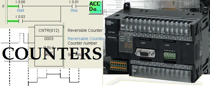
CNT – Counter – This is a decrementing counter
CNTR – Reversible Counter – This will increment or decrement depending on the input.
CNR – Reset Counter / Timer – This instruction will reset a range of timers or counters.
All of the above instructions use BCD (Binary Coded Decimal). If you put an ‘X’ behind each of the above instructions you will indicate the same operation with values in binary. You would use binary if you would like a higher count value.
Let’s take a look at some sample programs. There are several ways in which we can use the counter instructions. You can apply all of the following examples to the basic counter instructions. We have wired into input 0.08 a magnetic pick up that will provide pulses into the PLC. This will serve to demonstrate the counter functions.
Memory Retentive Counter – Omron CP1H Counters
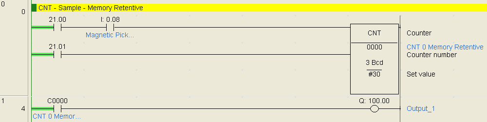
When bit 21.00 turns on it will enable the pulses from our magnetic pick-up sensor. This will start to count down from the set value (SV) of 30. Once the present value (PV) reaches 0, the counter 0 output bit will be turned on which will turn the output on. The output will remain on until the reset signal from input 21.01 is activated. When power is cycled on the PLC or the mode of the PLC changes from run to program, the PV of the counter is remembered.
Memory Retentive Timer (Using Counter) – Omron CP1H Counters
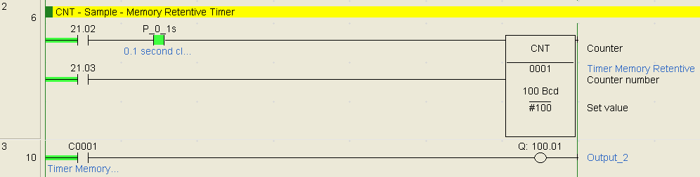
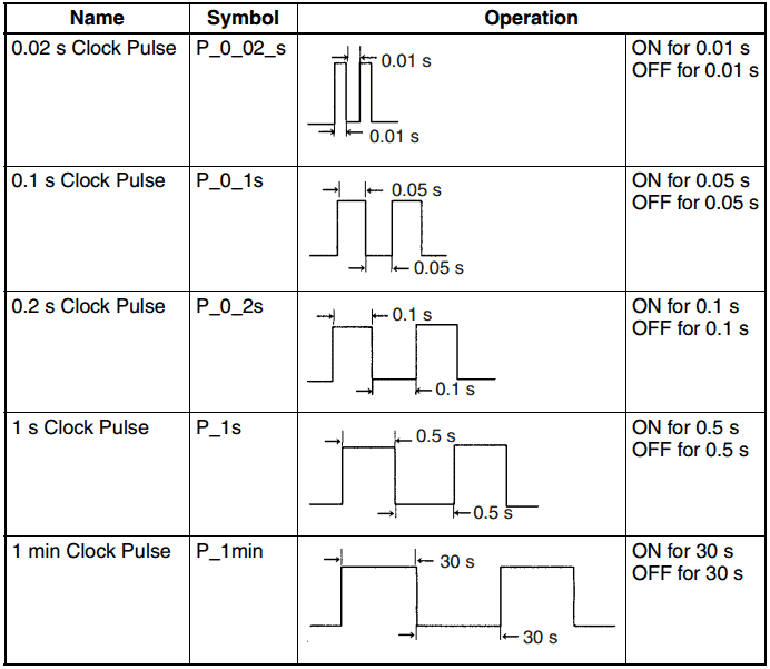
We can make a memory retentive timer using a counter and a clock bit flag. When bit 21.02 turns on, it will allow the 0.1 sec pulse bit to trigger the input for counter 1. The SV valve is set for 100 which is equivalent to 10 seconds. After the counter counts down to 0 the output (100.01) will be turned on via the C0001 bit. You can adjust the set time by the SV value or use a different clock bit value.
Non-Memory Retentive Counter – Omron CP1H Counters
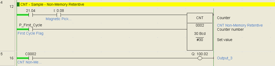
Using a first scan flag on the reset of the counter will make the counter non-memory retentive. This means it will reset when power is turned off of the PLC or the PLC mode changes from program to run. In our example, when bit 21.04 is turned on it will allow the magnetic pickup pulses to activate counter 2. Counter 2 output bit will then turn on output 100.02.
CNTR – Reversible Counter – Omron CP1H Counters
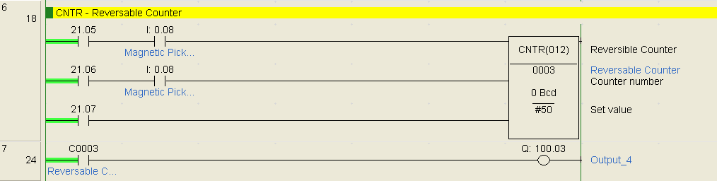
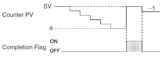
The reversible counter has three inputs; increment, decrement and reset. Here is the timing chart for this instruction:
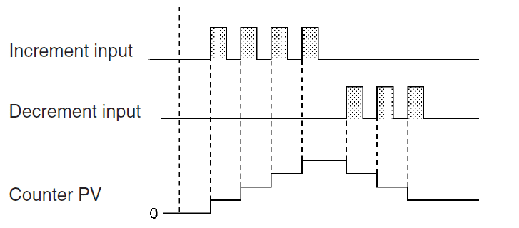
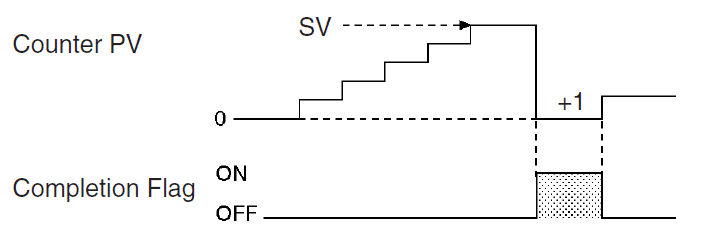
The output will turn on if the counter PV value increments one past the SV.
When decrementing the counter the output will turn on when the counter decrements one past the 0. This will place the counter back at the SV.
CNR – Counter Reset – Omron CP1H Counters
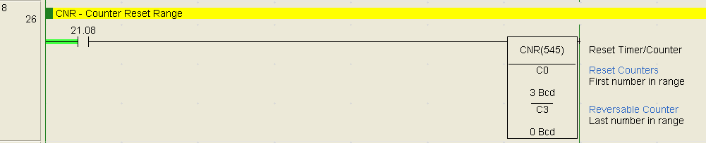
The counter reset instruction can be used to reset a range of counters or timers. In our example the counter range C0 to C3 is reset with bit 21.08 is turned on. This instruction is useful for resetting the entire machine timers and counters.
Frequency that we can read the inputs are expressed as pulses per second which is hertz. If the scan of our PLC is 1 msec then we can read the input condition 1000 times per second. This can then be expressed as 1Khz. Inputs usually will have a filter. This filter will prevent the input signal from bouncing when inputs switch. Bouncing usually occurs when mechanical relays are used in conjunction with the PLC input signal. The CP1H PLC has a default of 8msec input filter for the inputs. This can be changed through the setup of the PLC.
The CP1H PLC also has four high-speed counter inputs. Each of these inputs can be 50 kHz input frequency using the differential phase inputs. This increases to 100 kHz when using any of the other three modes.
There is also an Input Interrupts Counter Mode. This will allow you to set up 8 different counters that will activate an interrupt task when the count reaches the set value. The maximum response frequency is 5 kHz.
See the YouTube video below on counters in the Omron CP1H PLC.
The following is a list of manuals associated with the CP1H programmable logic controller. See the descriptions for each of these manuals in the first post: Omron CP1H System Hardware
W450 – SYSMAC CP Series CP1H CPU Unit Operation Manual
W451 – SYSMAC CP Series CP1H CPU Unit Programming Manual
W342 – SYSMAC CS/CJ series Communications Commands Reference Manual
W446 – SYSMAC CX-Programmer Ver. 6.1 Operation Manual
W447 – SYSMAC CX-Programmer Ver. 6.1 Operation Manual Function Blocks
W444 – CX-One FA Integrated Tool Package Setup Manual
W445 – CX-Integrator Operation Manual
W344 – CX-Protocol Operation Manual
You can download the PLC program as discussed above here.
Next time we will look at data movement in the Omron CP1H PLC.
Watch on YouTube : Omron CP1H Counters
If you have any questions or need further information please contact me.
Thank you,
Garry
If you’re like most of my readers, you’re committed to learning about technology. Numbering systems used in PLC’s are not difficult to learn and understand. We will walk through the numbering systems used in PLCs. This includes Bits, Decimal, Hexadecimal, ASCII and Floating Point.
To get this free article, subscribe to my free email newsletter.
Use the information to inform other people how numbering systems work. Sign up now.

The ‘Robust Data Logging for Free’ eBook is also available as a free download. The link is included when you subscribe to ACC Automation.