The Omron CP1H programmable logic controller has several different ways to control the program and the way in which your program executes. Sequence control, Subroutines, and Step instructions can be used. These are just a few ways in which the controller will execute your logic using a synchronous PLC scan. Understanding the PLC program scan will explain the synchronous and asynchronous program scanning.
Interlocks, Jumps, For Next Loops, Subroutines and Step instructions are some of the ways in which we can control our program in the PLC. We will be looking at some of these instructions in the Omron CP1H PLC. Examples of some of the instructions will be presented.
Previously in this CP1H series, we have discussed:
System Hardware – Video
CX-Programmer – Video
Establish Communication – Video
Setting, Forcing and Online Editing – Video
Numbering System and Addressing – Video
CP1H Timers – Video
Counters – Video
Data Movement – Video
Compare Instructions – Video
Data Shift Instructions
– Video Part 1
– Video Part 2
Math Instructions – Video
Data Conversion – Video
Program Control Instructions – Video
Table Data Instructions – Video
Data Control Instructions – Video
AdvancedHMI Communication – Video
Several different program control instructions are available in the CP1H. A full explanation can be obtained by using the help menu in the CX-Programmer software or the Programming Manual for the CP1H. Links are provided at the end of this post.
Instructions can have different variations.
Let’s look at when this instruction will execute:
SBS(091) when used will be scanned and executed every cycle of the PLC that the input condition is on.
@SBS(091) when used will be executed when the input condition turns from off to on. This will trigger the instruction to happen only once.
Please refer to the programming manual or help file in CX-Programmer for different variations of the instructions that you want to use. We will now go over some of the program control instructions in the Omron CP1H. This will give you a general idea of the instructions available.
Sequence Control Instruction – Omron CP1H
The first few program control instructions are basic for all Omron programs.
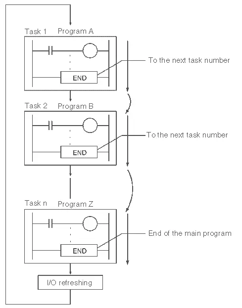
END: END(001)
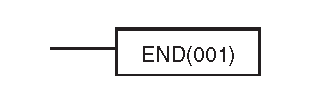
This instruction indicates the end of the program. It can also be used in interrupt tasks to indicate the end of the task. At least one END instruction must be present in your program in order to indicate the end of the program. This automatically happens when you start a new project with CX-programmer.
NOP(000)
This instruction means no operation. The instruction has no function when scanned in the program. It is sometimes used as a place holder when programming in the mnemonic. (CX-Programmer – View Mnemonics (Alt +M)) You will see this instruction past the END statement in your program. This will not display in ladder logic.
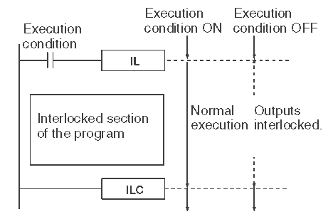
INTERLOCK and INTERLOCK CLEAR: IL(002) and ILC(003) – Omron CP1H
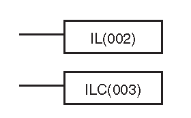
These instructions are used together. When the execution condition is off, all of the outputs between the interlock and interlock clear are interlocked. (Reset / Off) If the execution condition is on then the program executes normally.
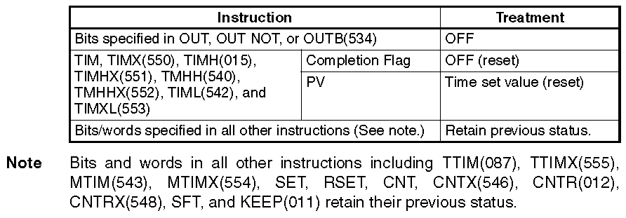
The following table shows various outputs and the way in which the interlock function will be executed.
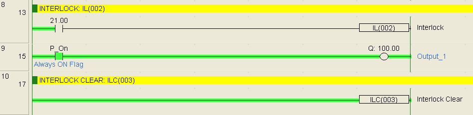
In our example, we are using an always-on flag to turn on the first output between the two instructions. When 21.00 (execution condition) is turned on the program functions as expected and turns on the output 100.00. If 21.00 is off the output of 100.00 is also off.
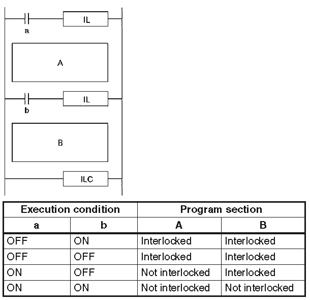
You can have more than one interlock instruction for an interlock clear. This will allow you to section off your program in blocks depending on the execution condition.
 The Omron CP1H also has multi-interlock differentiation hold, multi-interlock differentiation release and multi-interlock clear instructions. (MILH(517), MILR(518), and MILC(519)) Unlike the standard interlocks, these instructions can be nested together.
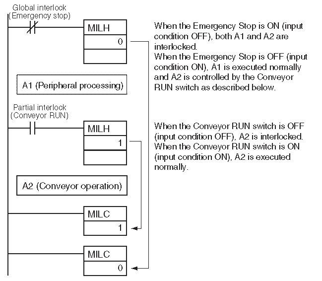
You can see that MILH 1 is nested within MILH 0.
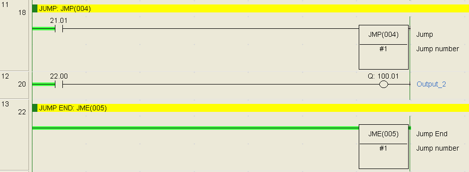
JUMP and JUMP END: JMP(004) and JME(005) – Omron CP1H
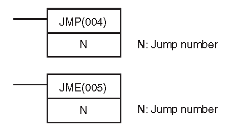
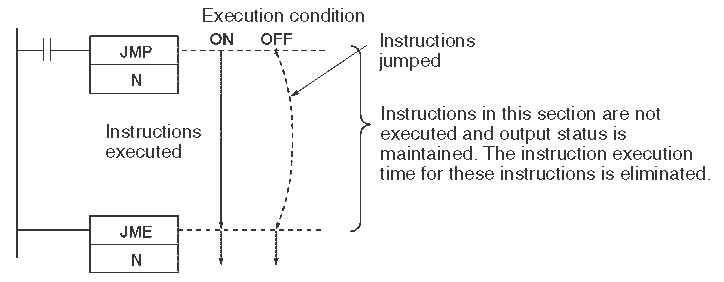
When the execution condition is on, no jump is made and the program is executed normally. If the condition is off then the program jumps directly to the first jump end instruction with the same number. The instructions between the jump and jump end are not executed so the previous status of the outputs is maintained.
The CP1H also offers other jump and jump end instructions.
CONDITIONAL JUMP: CJP(510)/CJPN(511)
MULTIPLE JUMP and JUMP END: JMP0(515) and JME0(516)
The following chart will explain the differences between the instruction.

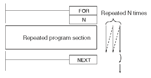
FOR-NEXT LOOPS: FOR(512)/NEXT(513) – Omron CP1H
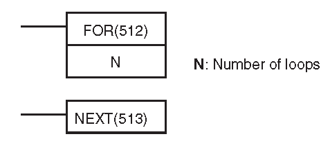
The instructions between the FOR and NEXT are repeated for a specific number of times.
We use the BREAK instruction to exit the FOR NEXT loop without finishing. We could also use the JUMP and JUMP END instructions to exit out of this loop.
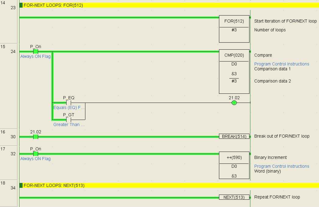
In our example, we are using a comparison to control the BREAK instruction. If DM is equal to or greater than 3 the break will be activated. This means that our FOR NEXT loop will activate for one scan. (Repeat 3 times)

FOR NEXT loops can be nested up to 15 levels. The above shows you one nested FOR NEXT loop.
Subroutines – Omron CP1H
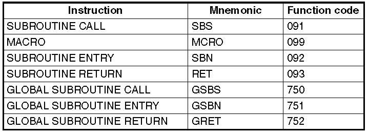
Subroutines are used to split your program up into manageable sections or use code several different times in the scan. The following is a list of subroutine instructions in the Omron CP1H.
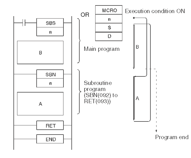
Subroutines are used with a SUBROUTINE CALL that will call up the subroutine number within the scan of the PLC. The SUBROUTINE ENTRY is the name or number of the subroutine that you are calling. It is the start of the code that will be executed.
SUBROUTINE RETURN is placed at the end of the subroutine code. It tells the PLC to resume scanning the code after the location that the SUBROUTINE CALL was executed.
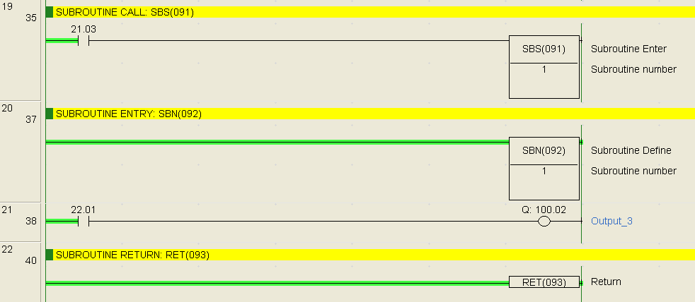
SUBROUTINE CALL: SBS(091)
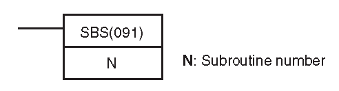
This instruction will call the subroutine.
SUBROUTINE ENTRY: SBN(092)
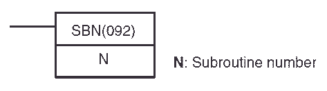
This marks the start of the subroutine. This is always programmed within the same task as the subroutine call instruction.
SUBROUTINE RETURN: RET(093)

This indicates the end of the subroutine.
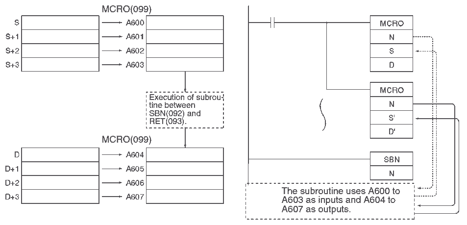
MACRO: MCRO(099)
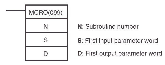
The MACRO instruction is similar to the SUBROUTINE CALL. It will call the subroutine but allow you to specify the inputs and outputs for the subroutine. S to S+3 are transferred to the macro area A600 to A603. The subroutine is executed and the outputs are transferred from A604 to A607 to D to D+3.
Here is the basic subroutine program.
Subroutines can be nested up to 16 levels.
In our example input, 21.03 will call up subroutine 1. If 22.01 is on then output 100.02 is turned on. You will notice that the status of the outputs are maintained until they are scanned again.
The Omron CP1H also has Global Subroutines. They are used to interrupt routines within the scan. The instructions available are as follows: GLOBAL SUBROUTINE CALL: GSBS(750), GLOBAL SUBROUTINE ENTRY: GSBN(751), and GLOBAL SUBROUTINE RETURN: GRET(752)
Step Instructions – Omron CP1H
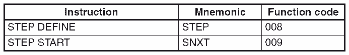
The step and step next instructions are used to set up breakpoints between sections in a large program.
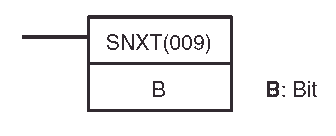
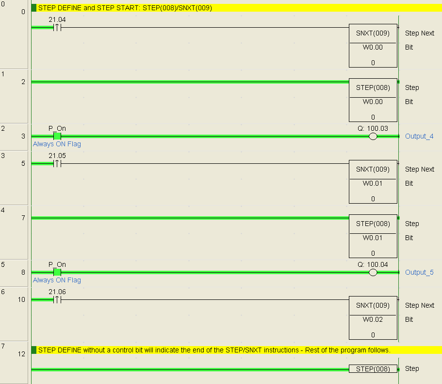
The SNXT (009) is placed immediately before the STEP(008) instruction and controls step execution by turning the specified control bit ON. If there is another step immediately before the SNXT (009), it also turns OFF the control bit of that process.

When defining the beginning of a step, a control bit is specified.

Ending the step program area is a STEP(008) instruction without a control bit.
The step programming area is usually at the beginning rungs of the ladder logic program.
When SNXT (009) turns ON the control bit for a step, the control bit B of the current instruction will be reset (turned OFF) and the step controlled by bit B will become interlocked.
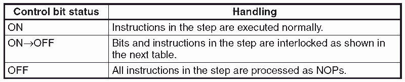
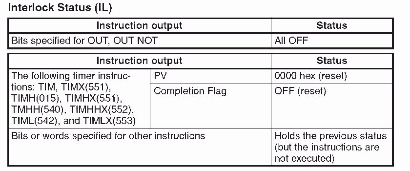
Handling of outputs and instructions in a step will change according to the ON/OFF status of the control bit B. (The status of the control bit is controlled by SNXT(009)). When control bit B is turned OFF, the instructions in the step are reset and are interlocked. Refer to the following tables.
Here is an example of the step/step next instructions.
You can see that we have many different program control instructions in the Omron CP1H. This should give you a good idea of what is possible.
See the YouTube video below on program control instructions in the Omron CP1H PLC.
The following is a list of manuals associated with the CP1H programmable logic controller. See the descriptions for each of these manuals in the first post: Omron CP1H System Hardware
W450 – SYSMAC CP Series CP1H CPU Unit Operation Manual
W451 – SYSMAC CP Series CP1H CPU Unit Programming Manual
W342 – SYSMAC CS/CJ series Communications Commands Reference Manual
W446 – SYSMAC CX-Programmer Ver. 6.1 Operation Manual
W447 – SYSMAC CX-Programmer Ver. 6.1 Operation Manual Function Blocks
W444 – CX-One FA Integrated Tool Package Setup Manual
W445 – CX-Integrator Operation Manual
W344 – CX-Protocol Operation Manual
You can download the PLC program as discussed above here.
Next time we will look at table data processing instructions in the Omron CP1H PLC.
Watch on YouTube : Omron CP1H Program Control Instructions
If you have any questions or need further information please contact me.
Thank you,
Garry
If you’re like most of my readers, you’re committed to learning about technology. Numbering systems used in PLC’s are not difficult to learn and understand. We will walk through the numbering systems used in PLCs. This includes Bits, Decimal, Hexadecimal, ASCII and Floating Point.
To get this free article, subscribe to my free email newsletter.
Use the information to inform other people how numbering systems work. Sign up now.

The ‘Robust Data Logging for Free’ eBook is also available as a free download. The link is included when you subscribe to ACC Automation.