We will now establish Omron CP1H communication using the built-in USB connection. CX-Programmer will be used to communicate. The Omron CP1H series of programmable logic controllers are programmed from CX-Programmer. CX-Programmer is part of the Omron CX-One Factory Automation Integrated Tool Package. We will now establish communication with our CP1H PLC using CX-Programmer. We will be using the USB connection (Built into the CPU) as well as an RS485 connection using the CP1W-CIF11 module. The Start-Stop and Jog circuit that we developed last time will be transferred to the PLC unit. We will then verify that the program in the PLC is the same as the program logic in CX-Programmer.
Previously in this CP1H series, we have discussed:
System Hardware – Video
CX-Programmer – Video
Establish Communication – Video
Setting, Forcing and Online Editing – Video
Numbering System and Addressing – Video
CP1H Timers – Video
Counters – Video
Data Movement – Video
Compare Instructions – Video
Data Shift Instructions
– Video Part 1
– Video Part 2
Math Instructions – Video
Data Conversion – Video
Program Control Instructions – Video
Table Data Instructions – Video
Data Control Instructions – Video
AdvancedHMI Communication – Video
As mentioned before, the CX-Programmer Introduction Guide provides step by step for the process of using the software. Here is the URL link for this free literature:
https://www.fa.omron.com.cn/data_pdf/mnu/r132-e1-05_cx-programmer.pdf?id=1605

A copy of this guide is a good tool to use when you learn to program using the CX-Programmer.
CX-One software has been around for a number of years. You can now get your copy from many online stores such as Ebay at a reduced cost.
Let us start with establishing communication using the CP1W-CIF11 RS-422A/485 Option Board. We will set the hardware and then the software.
Hardware – Omron CP1H Communication
CP1W-CIF11 RS-422A/485 Option Board
This option board can be mounted on either board slot on the PLC CPU. The unit has a communication status indication and a terminal strip on the front. Dip switches are located on the back of the unit and are used to set up 2 (RS-485) or 4 (RS422) wire communication.
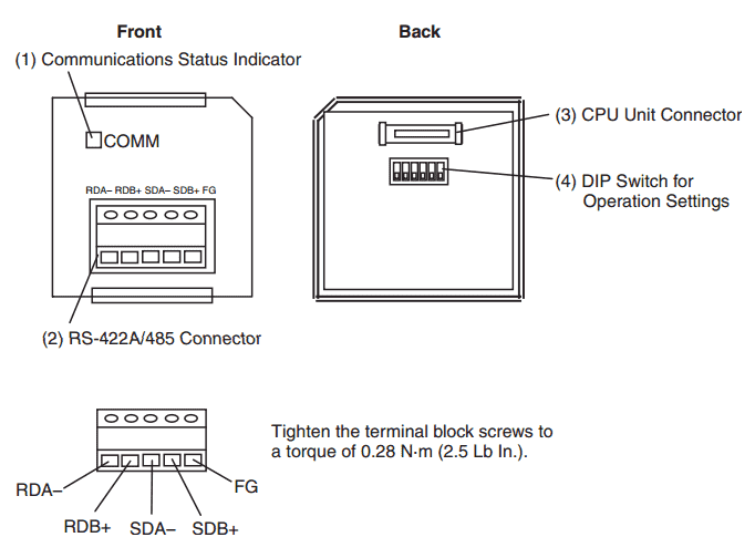
In our case we will be communicating RS-485 so we will wire the terminal up as follows:
Adapter (RJ12) to CP1W-CIF11
3 red SG+ ————— RDB+
4 green SG- ————– RDA-
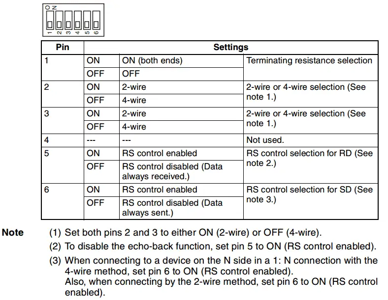
The following are the dip switches. In our case we will have everything on except pins 1 and 4. When you see a ‘Not used’ on an Omron dip switch, it is best to leave this in the off position.
NOTE: Serial adapters such as this must have the software installed prior to connecting the adaptor to your computer. The USB to RS-485 PC Adapter that we are using is from Automation Direct. Here is a link to explain the installation of this unit. USB to RS485 PC Adaptor Installation
Software
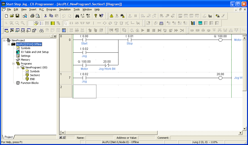
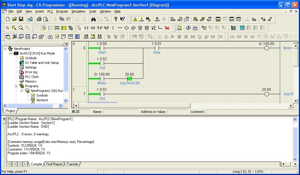
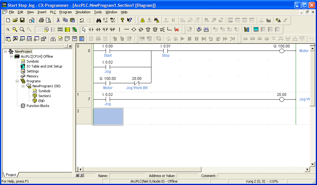
We will start by calling up the Start-Stop Jog program that we made last time in CX programmer.
Under the project tree, double click on the PLC (AccPLC[CP1H] Offline). Alternatively, you can go to the main menu and select PLC | Change Model.
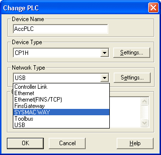
Change the Network Type to ‘SYSMAC WAY’. Now select ‘Settings…’

Under ‘Network Settings [SYSMAC WAY]’ we will leave everything at the default settings. Please ensure that the Host link Unit Number is set at zero. (0) This should be the default.
Now select the Driver tab at the top of the window.
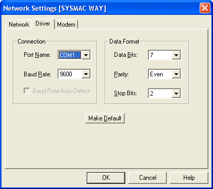
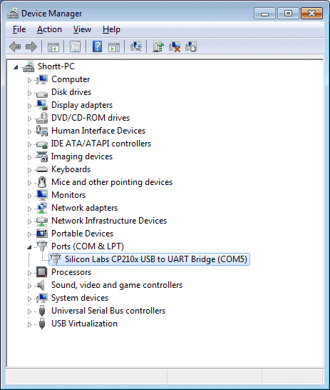
Set the Connection Port Name to the port when installing the USB to RS485 adapter. Leave the baud rate and data format to the default settings. Omron equipment using serial communication will usually have the following as the default values. 9600 baud, Even parity, 2 stop bits, and 7 data bits. You can see the port number by going to your device manager in windows and looking at the communication port settings.
Hit OK to save and get out of network settings. Now hit OK to save and get out of the Change PLC window. We are now set to communicate to the PLC.

The first icon triangle is the normal online. This will enable you to go online with the PLC of the device type and method specified in the Change PLC window.
The icon with the binoculars and triangle is the auto online. This button will automatically recognize connected PLC and will upload all data such as programs from the PLC.
Hit the normal online triangle.
You will get a warning message that you are about to connect to the PLC. Do you wish to continue?
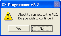
Click Yes.
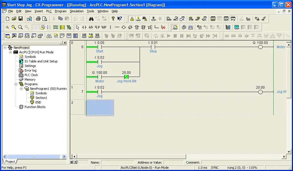
We are now connected to the PLC.
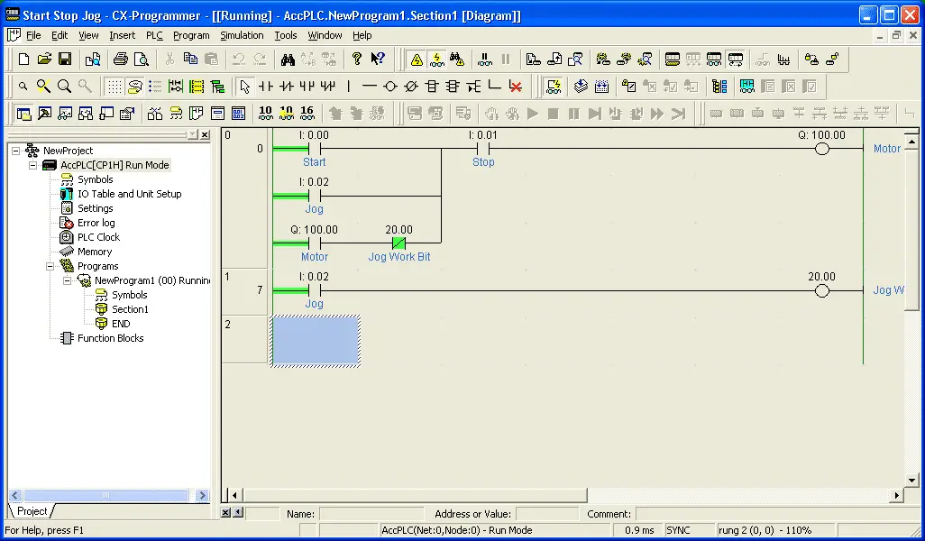
The icon that looks like glasses with a lightning symbol will toggle the on/off of the PLC monitoring. That is you will see the ladder rungs being monitored and will be shown in a specified color.
Note: When online to the PLC you will see the project tree will show the PLC condition. In our case, it is showing Run Mode.
Transfer the Program – Omron CP1H Communication
We have established communication with the PLC. Let’s transfer our program and verify that it is the same as what we see on the computer.
Transfer to the PLC
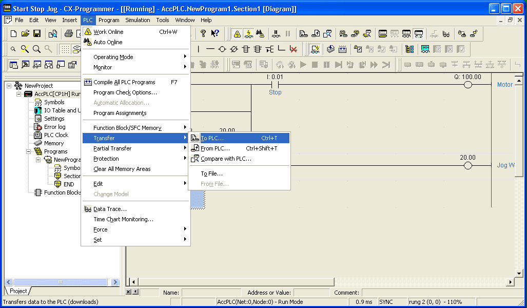
Select from the main menu PLC | Transfer | To PLC…. You could also use the keys Ctrl + T.
The following Download Options window will now appear.
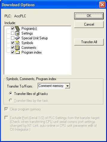
Select OK to transfer the program.
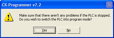
A warning window will now appear.
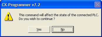
Select Yes.
Additional warnings may appear depending on the current mode of the PLC. If an existing program is running, it will ask if it is OK to go into program mode. This will stop the execution of the existing program.
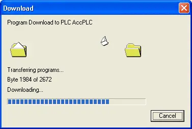
The download will now start.
When the download is finished, the download window will indicate if it was successful.
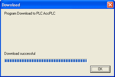
Hit OK to acknowledge.
You will now be asked if it is OK to return the PLC to run mode.
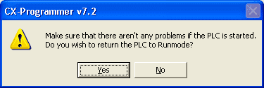
Select Yes.
The output window is now displayed indicating that the program has no errors and warnings. It also will show you the amount of memory used.
You can hit the ‘X’ in the top left corner of the output window to close it or you can hit Alt+2.
Verify the program in the PLC and CX-Programmer are the same.
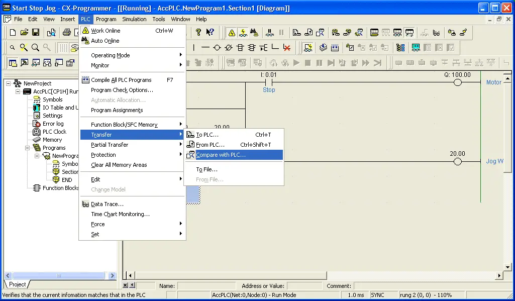
Select PLC | Transfer | Compare with PLC …
A Compare Options window will appear.
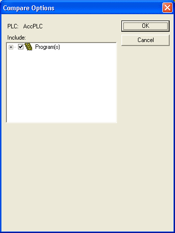
Select OK.
The comparison process will begin.
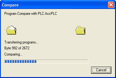
A window will appear indicating that the comparison was successful. This means that the program in the PLC is an exact match of the one in CX-Programmer.
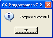
Hit OK.
We can now go offline by hitting the normal online mode triangle again.
USB Connection – Omron CP1H Communication
We will now select the USB connection to the PLC that is built into the CP1H. This uses a standard USB printer cable for communication.
Under the project tree, double click on the PLC (AccPLC[CP1H] Offline). Alternatively, you can go to the main menu and select PLC | Change Model.
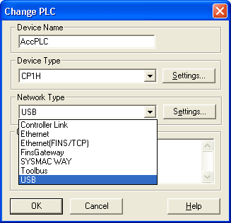
Change the Network Type to ‘USB’. Now select ‘Settings…’
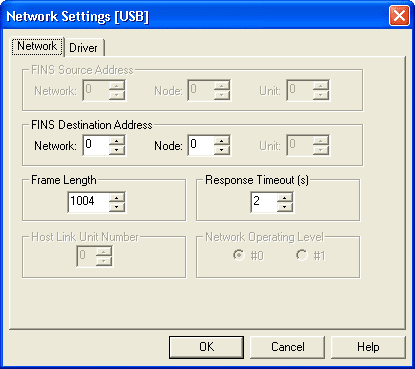
Leave everything as the default. Verify that the network and node number are zero. (0).
We can select OK to save and get out of the network settings. Then hit OK to save and get out of the Change PLC settings.
We are not set to establish communication using our USB cable. Select the normal online triangle to connect. This is the same procedure as mentioned above.
See the connection established with the CP1H PLC in action by watching the YouTube video below.
The following is a list of manuals associated with the CP1H programmable logic controller. See the descriptions for each of these manuals in the first post: Omron CP1H System Hardware
W450 – SYSMAC CP Series CP1H CPU Unit Operation Manual
W451 – SYSMAC CP Series CP1H CPU Unit Programming Manual
W342 – SYSMAC CS/CJseries Communications Commands Reference Manual
W446 – SYSMAC CX-Programmer Ver. 6.1 Operation Manual
W447 – SYSMAC CX-Programmer Ver. 6.1 Operation Manual Function Blocks
W444 – CX-One FA Integrated Tool Package Setup Manual
W445 – CX-Integrator Operation Manual
W344 – CX-Protocol Operation Manual
You can download the PLC program as discussed above here.
Next time we will look at setting and forcing I/O alone and also online editing with the CP1H PLC.
Watch on YouTube: Omron CP1H Establish Communication
If you have any questions or need further information please contact me.
Thank you,
Garry
If you’re like most of my readers, you’re committed to learning about technology. Numbering systems used in PLC’s are not difficult to learn and understand. We will walk through the numbering systems used in PLCs. This includes Bits, Decimal, Hexadecimal, ASCII, and Floating Point.
To get this free article, subscribe to my free email newsletter.
Use the information to inform other people how numbering systems work. Sign up now.

The ‘Robust Data Logging for Free’ eBook is also available as a free download. The link is included when you subscribe to ACC Automation.