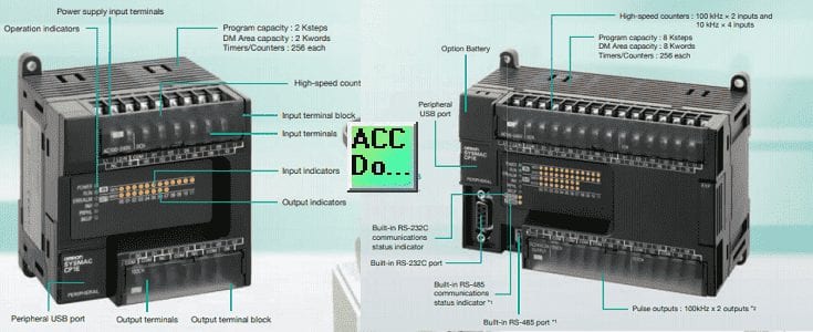
Omron CP1E (Datasheet)
CPU Units
CPU Options Units
Expansion Units
Maintenance and Options Parts
Programming Software / Cable
Manuals
Omron CP1E E(S) Type CPU Configuration
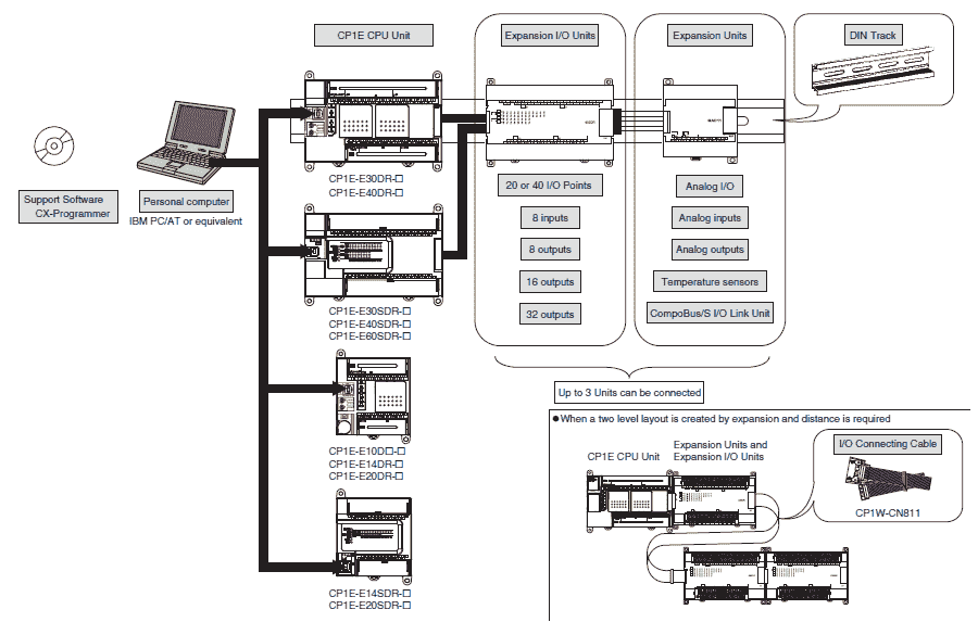
For CP1E CPU Units, the following I/O memory area will be unstable after a power interruption.
• DM Area (D) (excluding words backed up to the EEPROM using the DM function)
• Holding Area (H)
• Counter Present Values and Completion Flags (C)
• Auxiliary Area related to clock functions(A)
Mount the CP1W-BAT01 Battery (sold separately) to an N/NA(S)-type CPU Unit if
data in the above areas need to be retained after a power interruption. A Battery cannot be
mounted to an E(S)-type CPU Unit.
Omron CP1E N/NA(S) Type CPU Configuration
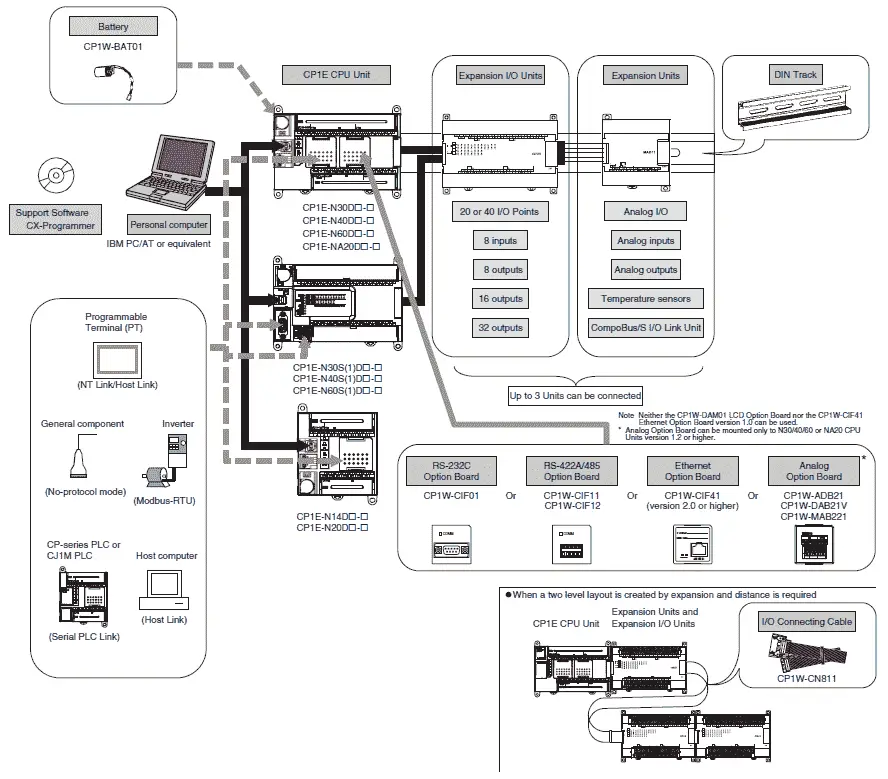
For CP1E CPU Units, the following I/O memory area will be unstable after a power interruption.
• DM Area (D) (excluding words backed up to the EEPROM using the DM function)
• Holding Area (H)
• Counter Present Values and Completion Flags (C)
• Auxiliary Area related to clock functions(A)
Mount the CP1W-BAT01 Battery (sold separately) to a N/NA(S)-type CPU Unit if
data in the above areas need to be retained after a power interruption. A Battery cannot be
mounted to an E(S)-type CPU Unit.
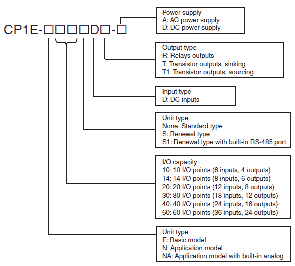
| CPU Units | Power Supply | Inputs | Outputs | Model Number |
| ES Type 14 I/O | AC 100 to 240 VAC | 8 DC | 6 Relay | CP1E-E14SDR-A |
| ES Type 20 I/O | AC 100 to 240 VAC | 12 DC | 8 Relay | CP1E-E20SDR-A |
| ES Type 30 I/O | AC 100 to 240 VAC | 18 DC | 12 Relay | CP1E-E30SDR-A |
| ES Type 40 I/O | AC 100 to 240 VAC | 24 DC | 16 Relay | CP1E-E40SDR-A |
| ES Type 60 I/O | AC 100 to 240 VAC | 36 DC | 24 Relay | CP1E-E60SDR-A |
| E Type 10 I/O | AC 100 to 240 VAC | 6 DC | 4 Relay | CP1E-E10DR-A |
| E Type 10 I/O | AC 100 to 240 VAC | 6 DC | 4 Transistor Sinking | CP1E-E10DT-A |
| E Type 10 I/O | AC 100 to 240 VAC | 6 DC | 4 Transistor Sourcing | CP1E-E10DT1-A |
| E Type 10 I/O | DC 24V | 6 DC | 4 Relay | CP1E-E10DR-D |
| E Type 10 I/O | DC 24V | 6 DC | 4 Transistor Sinking | CP1E-E10DT-D |
| E Type 10 I/O | DC 24V | 6 DC | 4 Transistor Sourcing | CP1E-E10DT1-D |
| E Type 14 I/O | AC 100 to 240 VAC | 8 DC | 6 Relay | CP1E-E14DR-A |
| E Type 20 I/O | AC 100 to 240 VAC | 12 DC | 8 Relay | CP1E-E20DR-A |
| E Type 30 I/O | AC 100 to 240 VAC | 18 DC | 12 Relay | CP1E-E30DR-A |
| E Type 40 I/O | AC 100 to 240 VAC | 24 DC | 16 Relay | CP1E-E40DR-A |
| NS Type 30 I/O | AC 100 to 240 VAC | 18 DC | 12 Relay | CP1E-N30SDR-A |
| NS Type 30 I/O | DC 24V | 18 DC | 12 Transistor Sinking | CP1E-N30SDT-D |
| NS Type 30 I/O | DC 24V | 18 DC | 12 Transistor Sourcing | CP1E-N30SDT1-D |
| NS1 Type 30 I/O | AC 100 to 240 VAC | 18 DC | 12 Relay | CP1E-N30S1DR-A |
| NS1 Type 30 I/O | DC 24V | 18 DC | 12 Transistor Sinking | CP1E-N30S1DT-D |
| NS1 Type 30 I/O | DC 24V | 18 DC | 12 Transistor Sourcing | CP1E-N30S1DT1-D |
| NS Type 40 I/O | AC 100 to 240 VAC | 24 DC | 16 Relay | CP1E-N40SDR-A |
| NS Type 40 I/O | DC 24V | 24 DC | 16 Transistor Sinking | CP1E-N40SDT-D |
| NS Type 40 I/O | DC 24V | 24 DC | 16 Transistor Sourcing | CP1E-N40SDT1-D |
| NS1 Type 40 I/O | AC 100 to 240 VAC | 24 DC | 16 Relay | CP1E-N40S1DR-A |
| NS1 Type 40 I/O | DC 24V | 24 DC | 16 Transistor Sinking | CP1E-N40S1DT-D |
| NS1 Type 40 I/O | DC 24V | 24 DC | 16 Transistor Sourcing | CP1E-N40S1DT1-D |
| NS Type 60 I/O | AC 100 to 240 VAC | 36 DC | 24 Relay | CP1E-N60SDR-A |
| NS Type 60 I/O | DC 24V | 36 DC | 24 Transistor Sinking | CP1E-N60SDT-D |
| NS Type 60 I/O | DC 24V | 36 DC | 24 Transistor Sourcing | CP1E-N60SDT1-D |
| NS1 Type 60 I/O | AC 100 to 240 VAC | 36 DC | 24 Relay | CP1E-N60S1DR-A |
| NS1 Type 60 I/O | DC 24V | 36 DC | 24 Transistor Sinking | CP1E-N60S1DT-D |
| NS1 Type 60 I/O | DC 24V | 36 DC | 24 Transistor Sourcing | CP1E-N60S1DT1-D |
| N Type 14 I/O | AC 100 to 240 VAC | 8 DC | 6 Relay | CP1E-N14DR-A |
| N Type 14 I/O | AC 100 to 240 VAC | 8 DC | 6 Transistor Sinking | CP1E-N14DT-A |
| N Type 14 I/O | AC 100 to 240 VAC | 8 DC | 6 Transistor Sourcing | CP1E-N14DT1-A |
| N Type 14 I/O | DC 24V | 8 DC | 6 Relay | CP1E-N14DR-D |
| N Type 14 I/O | DC 24V | 8 DC | 6 Transistor Sinking | CP1E-N14DT-D |
| N Type 14 I/O | DC 24V | 8 DC | 6 Transistor Sourcing | CP1E-N14DT1-D |
| N Type 20 I/O | AC 100 to 240 VAC | 12 DC | 8 Relay | CP1E-N20DR-A |
| N Type 20 I/O | AC 100 to 240 VAC | 12 DC | 8 Transistor Sinking | CP1E-N20DT-A |
| N Type 20 I/O | AC 100 to 240 VAC | 12 DC | 8 Transistor Sourcing | CP1E-N20DT1-A |
| N Type 20 I/O | DC 24V | 12 DC | 8 Relay | CP1E-N20DR-D |
| N Type 20 I/O | DC 24V | 12 DC | 8 Transistor Sinking | CP1E-N20DT-D |
| N Type 20 I/O | DC 24V | 12 DC | 8 Transistor Sourcing | CP1E-N20DT1-D |
| N Type 30 I/O | AC 100 to 240 VAC | 18 DC | 12 Relay | CP1E-N30DR-A |
| N Type 30 I/O | AC 100 to 240 VAC | 18 DC | 12 Transistor Sinking | CP1E-N30DT-A |
| N Type 30 I/O | AC 100 to 240 VAC | 18 DC | 12 Transistor Sourcing | CP1E-N30DT1-A |
| N Type 30 I/O | DC 24V | 18 DC | 12 Relay | CP1E-N30DR-D |
| N Type 30 I/O | DC 24V | 18 DC | 12 Transistor Sinking | CP1E-N30DT-D |
| N Type 30 I/O | DC 24V | 18 DC | 12 Transistor Sourcing | CP1E-N30DT1-D |
| N Type 40 I/O | AC 100 to 240 VAC | 24 DC | 16 Relay | CP1E-N40DR-A |
| N Type 40 I/O | AC 100 to 240 VAC | 24 DC | 16 Transistor Sinking | CP1E-N40DT-A |
| N Type 40 I/O | AC 100 to 240 VAC | 24 DC | 16 Transistor Sourcing | CP1E-N40DT1-A |
| N Type 40 I/O | DC 24V | 24 DC | 16 Relay | CP1E-N40DR-D |
| N Type 40 I/O | DC 24V | 24 DC | 16 Transistor Sinking | CP1E-N40DT-D |
| N Type 40 I/O | DC 24V | 24 DC | 16 Transistor Sourcing | CP1E-N40DT1-D |
| N Type 60 I/O | AC 100 to 240 VAC | 36 DC | 24 Relay | CP1E-N60DR-A |
| N Type 60 I/O | AC 100 to 240 VAC | 36 DC | 24 Transistor Sinking | CP1E-N60DT-A |
| N Type 60 I/O | AC 100 to 240 VAC | 36 DC | 24 Transistor Sourcing | CP1E-N60DT1-A |
| N Type 60 I/O | DC 24V | 36 DC | 24 Relay | CP1E-N60DR-D |
| N Type 60 I/O | DC 24V | 36 DC | 24 Transistor Sinking | CP1E-N60DT-D |
| N Type 60 I/O | DC 24V | 36 DC | 24 Transistor Sourcing | CP1E-N60DT1-D |
| NA Type 20 I/O | AC 100 to 240 VAC | 12 DC + 2 AD | 8 Relay + 1 DA | CP1E-NA20DR-A |
| NA Type 20 I/O | DC 24VC | 12 DC + 2 AD | 8 Transistor Sinking + 1 DA | CP1E-NA20DT-D |
| NA Type 20 I/O | DC 24VC | 12 DC + 2 AD | 8 Transistor Sourcing + 1 DA | CP1E-NA20DT1-D |
ES Type – Memory capacity: 2K steps Data Memory capacity: 2K words. A battery cannot be mounted to an E-type CPU Unit.
E Type – Memory capacity: 2K steps Data Memory capacity: 2K words. A battery cannot be mounted to an E-type CPU Unit.
NS(1) Type – Memory capacity: 8K steps Data Memory capacity: 8K words.
N Type – Memory capacity: 8K steps Data Memory capacity: 8K words.
NA Type – Memory capacity: 8K steps Data Memory capacity: 8K words. Built-in Analog
| Name | Specifications | Model |
| RS-232C Option Board | Can be mounted in either CPU Unit Option Board slot 1 or 2. | CP1W-CIF01 |
| RS-422A/485 Option Board | Can be mounted in either CPU Unit Option Board slot 1 or 2. | CP1W-CIF11 |
| RS-422A/485 (Isolated-type) Option Board | Can be mounted in either CPU Unit Option Board slot 1 or 2. | CP1W-CIF12-V1 |
| Ethernet Option Board | Can be mounted in either CPU Unit Option Board slot 1 or 2. * | CP1W-CIF41 |
| LCD Option Board | Can be mounted only in the CPU Unit Option Board slot 1. | CP1W-DAM01 |
| Memory Cassette | Can be used for backing up programs or auto-booting. | CP1W-ME05M |
* When using CP1W-CIF41 Ver.1.0, one Ethernet port can be added.
| Product | Input | Output | Model |
| Input Unit | 8 pt 24 VDC | – | CP1W-8ED |
| Output Unit | – | 8 pt Relay | CP1W-8ER |
| Output Unit | – | 8 pt Transister (sinking) | CP1W-8ET |
| Output Unit | – | 8 pt Transister (sourcing) | CP1W-8ET1 |
| Output Unit | – | 16 pt Relay | CP1W-16ER |
| Output Unit | – | 16 pt Transister (sinking) | CP1W-16ET |
| Output Unit | – | 16 pt Transister (sourcing) | CP1W-16ET1 |
| Output Unit | – | 32 pt Relay | CP1W-32ER |
| Output Unit | – | 32 pt Transister (sinking) | CP1W-32ET |
| Output Unit | – | 32 pt Transister (sourcing) | CP1W-32ET1 |
| I/O Units | 12 | 8 pt Relay | CP1W-20EDR1 |
| I/O Units | 12 | 8 pt Transister (sinking) | CP1W-20EDT |
| I/O Units | 12 | 8 pt Transister (sourcing) | CP1W-20EDT1 |
| I/O Units | 24 | 16 pt Relay | CP1W-40EDR1 |
| I/O Units | 24 | 16 pt Transister (sinking) | CP1W-40EDT |
| I/O Units | 24 | 16 pt Transister (sourcing) | CP1W-40EDT1 |
| Analog Input | 4 ch -0 to 5, 1 to 5, 0 to 10, +/- 10VDC, 0 to 20 or 4-20 mA Resolution: 1/6000 | – | CP1W-AD041 |
| Analog Input | 4 ch -0 to 5, 1 to 5, 0 to 10, +/- 10VDC, 0 to 20 or 4-20 mA Resolution: 1/12000 | – | CP1W-AD042 |
| Analog Output | – | 2 ch 1 to 5, 0 to 10, +/- 10VDC, 0 to 20 or 4 to 20 mA Resolution: 1/6000 | CP1W-DA021 |
| Analog Output | – | 4 ch 1 to 5, 0 to 10, +/- 10VDC, 0 to 20 or 4 to 20 mA Resolution: 1/6000 | CP1W-DA041 |
| Analog Output | – | 4 ch 1 to 5, 0 to 10, +/- 10VDC, 0 to 20 or 4 to 20 mA Resolution: 1/12000 | CP1W-DA042 |
| Analog I/O Unit | 4 ch -0 to 5, 1 to 5, 0 to 10, +/- 10VDC, 0 to 20 or 4-20 mA Resolution: 1/12000 | 4 ch 1 to 5, 0 to 10, +/- 10VDC, 0 to 20 or 4 to 20 mA Resolution: 1/12000 | CP1W-MAD44 |
| Analog I/O Unit | 4 ch -0 to 5, 1 to 5, 0 to 10, +/- 10VDC, 0 to 20 or 4-20 mA Resolution: 1/12000 | 2 ch 1 to 5, 0 to 10, +/- 10VDC, 0 to 20 or 4 to 20 mA Resolution: 1/12000 | CP1W-MAD44 |
| Analog I/O Unit | 2 ch -0 to 5, 1 to 5, 0 to 10, +/- 10VDC, 0 to 20 or 4-20 mA Resolution: 1/6000 | 1 ch 1 to 5, 0 to 10, +/- 10VDC, 0 to 20 or 4 to 20 mA Resolution: 1/6000 | CP1W-MAD11 |
| Temperature Sensor Unit | 2 ch Platinum resistance thermometer Pt100 or JPt100 | – | CP1W-TS002 |
| Temperature Sensor Unit | 4 ch Thermocouple J or K | – | CP1W-TS101 |
| Temperature Sensor Unit | 4 ch Platinum resistance thermometer Pt100 or JPt100 | – | CP1W-TS102 |
| Temperature Sensor Unit | 4 ch Thermocouple J or K – 2 ch can be used as analog input 1 to 5, 0 to 10 VDC or 4 to 20 mA. Resolution: 1/12000 | – | CP1W-TS003 |
| Temperature Sensor Unit | 12 ch Thermocouple J or K | – | CP1W-TS004 |
| CompoBus/S I/O Link Unit | 8 CompoBus/s Slave | 8 CompoBus/s Slave | CP1W-SRT21 |
Note: Expansions units are also available using the CJ-series Special I/O Units and CPU Bus Units. See the brochure below for all of the CJ options.
| Name | Specifications | Model |
| I/O Connecting Cable | 80 cm (for CP1W Expansion Units) 6 cm provided with CP1W Expansion Units. | CP1W-CN811 |
| Battery Set | For CP1H CPU Units (Use batteries within two years of manufacture.) | CJ1W-BAT01 |
| DIN Track | Length 0.5 m, Height 7.3 mm | PFP-50N |
| DIN Track | Length 1 m, Height 7.3 mm | PFP-100N |
| DIN Track | Length 1 m, Height 16 mm | PFP-100N2 |
| DIN Track End Plate | Prevents units from sliding on DIN track | PFP-M |
Note: Please check the CPU type to see if expansion units are available to be used.
| Name | Specifications | Model |
| I/O Connecting Cable | 80 cm (for CP1W Expansion Units) 6 cm provided with CP1W Expansion Units. | CP1W-CN811 |
| Battery Set | Mounted in an N/NA(S)-type CPU Unit. | CP1W-BAT01 |
| DIN Track | Length 0.5 m, Height 7.3 mm | PFP-50N |
| DIN Track | Length 1 m, Height 7.3 mm | PFP-100N |
| DIN Track | Length 1 m, Height 16 mm | PFP-100N2 |
| DIN Track End Plate | Prevents units from sliding on DIN track | PFP-M |

Programming
CP1E PLCs are supported by CX-Programmer version 6.1 or higher. Update The CX-Programmer version automatically from the website using CX-Programmer version 7.0 (included with CX-One version 2.0).
The CX-One and CX-One Lite cannot be simultaneously installed on the same computer.
Multi licenses (3, 10, 30, or 50 licenses) and DVD media without licenses are also available for the CX-One.
To connect to a Personal Computer via a peripheral USB port, use a commercially available USB cable (A or B type, male).
Manuals
The following is a list of manuals associated with the CP1E programmable logic controller.
W479- CP1E CPU Unit Hardware – Provides an overview, mounting, I/O memory allocations, and troubleshooting.
W480 – CP1E CPU Unit Software – Programming instructions, methods, and functions.
W483 – CP1E CPU Unit Instructions Reference Manual – Specific program instructions for the PLC.
W446 – SYSMAC CX-Programmer Ver. 6.1 Operation Manual – Provides information on installing and operating CX programmer for all functions except function blocks.
W447 – SYSMAC CX-Programmer Ver. 6.1 Operation Manual Function Blocks
W444 – CX-One FA Integrated Tool Package Setup Manual – Provides an overview of the CX-One FA Integrated Tool and installation procedures.
W445 – CX-Integrator Operation Manual – Describes CX-Integrator operating procedures and provides information on network configurations.
W344 – CX-Protocol Operation Manual – Provides information on procedures for creating protocol macros. (Communication Sequences)

