Cofaso 7 is a computer-aided engineering (CAE) solution software package that includes PLC Design and Overview. Its special system technology with direct access to applicable logic for each schematic allows industry design and documentation for all solutions. Electrical engineering project tasks will become easier with Cofaso 7. This parameter controlled system is available in 13 languages and supports all the common windows versions.
Cofaso 7 meets all global evaluation standards. It offers complete authoring and editing of electrical engineering documents. Some of the features in the package include Cross-references, wiring lists, terminal diagrams, terminal connection diagrams, interconnect diagrams, PLC cross-references, mounting plate design, and more.
Cofaso provides flexible editing features:
XML, EXF, and graphics interfaces such as DXF guarantee data interchange with other CAx systems and ensure the integration of cofaso into the unified production chain. Article data of any kind be imported or incorporated. An intelligent article number search function provides an additional aid to locating components used in the diagram.
We will be creating a PLC drawing with 5 outputs. These outputs will be connected to another box with the same reference numbers. We will also show the automated connection list. Anytime a reference name is changed all document items will change for that reference. Let’s get started.
Cofaso 7 – Download Free for 30 days
Cofaso 7 can be downloaded free of charge for the first 30 days. It will run on a 64 bit or 32-bit windows machine with a minimum of 4 GB RAM memory. A screen resolution of 1600 x 1024 minimum and supports all graphic cards. Here is the link to download the software.
http://cofaso.com/Product/cofaso-7/3TCP69OsoyBqiugV-2F-jVI1A-3D–3D-
As with most software packages, disable any anti-virus packages before installing the software.
Starting Cofaso 7 CAE – PLC Design and Overview
Start the software by the icon on the desktop or use the start menu of windows and select “cofaso 7.2”

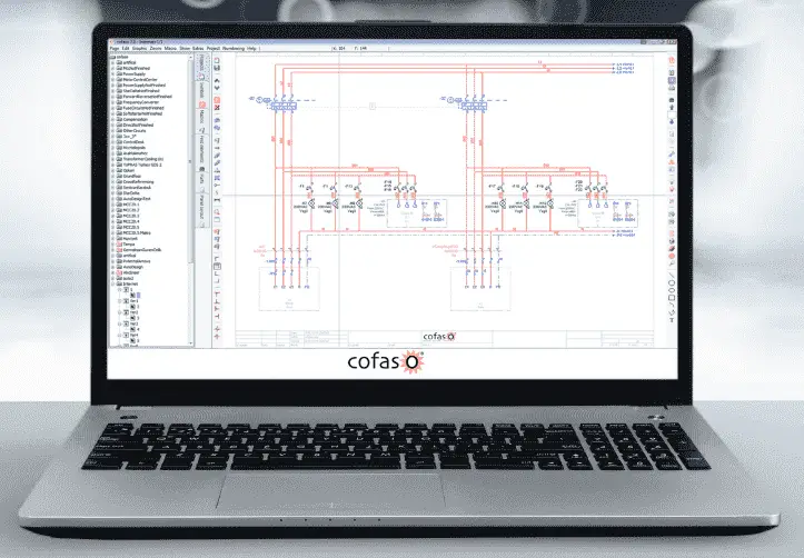
The splash screen of the software will be displayed followed by the opening of the last item that was being used.
Cofaso 7.2 will come loaded with example schematics for you to view. This will include Cofaso 7 PLC Design and Overview.
We will start a new project.
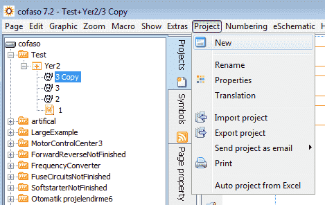
Select Project from the main menu and then New.
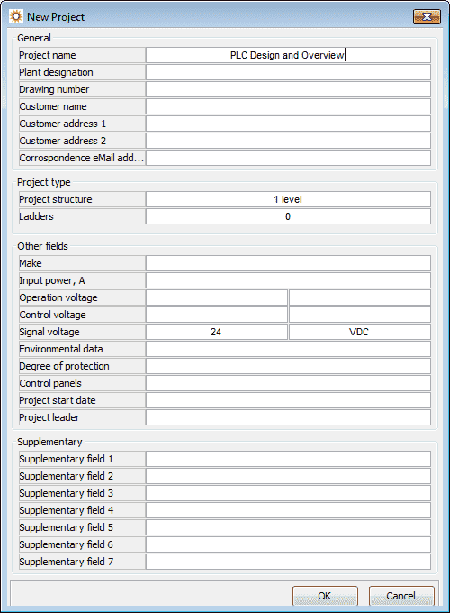
The new project window will be displayed. We can now enter our project name. Enter PLC Design and Overview. Hit OK.
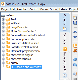
Our new project is now displayed under the projects tab of our software. (Cofaso 7 PLC Design and Overview)
While our new project is highlighted, select New from the menu. Alternatively, you can select Page from the main menu and then select New Page.
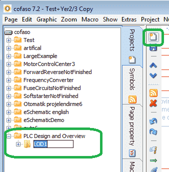
This will allow you to enter a new file under our PLC Design and Overview project. We can name this file anything that we want. We will leave this as the default LOD1 file name.
Select New again to create a page in the file.
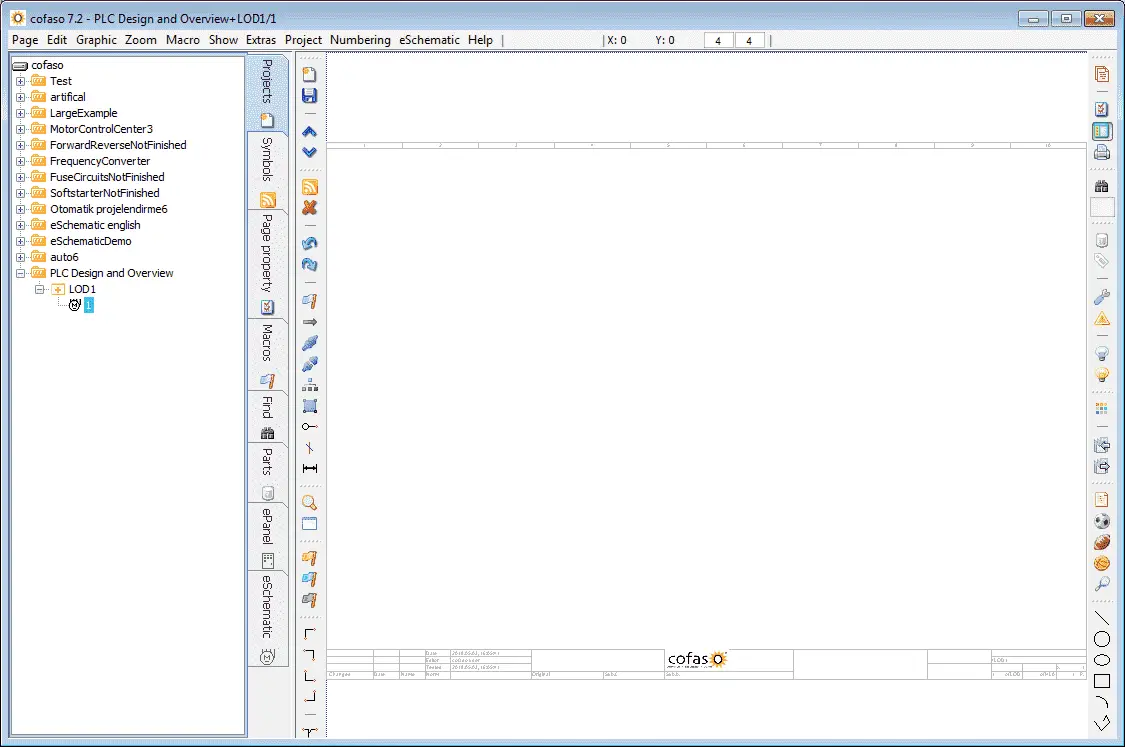
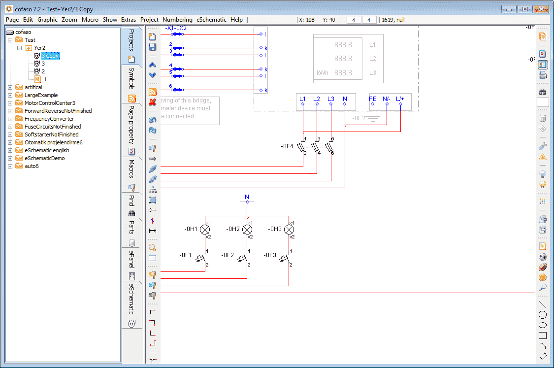
We will leave the default name of 1. This is where we will draw our terminal connections. On our page, you will see the titles along the bottom. Our default page is too large to see all at once. We can use zoom to look closer at the items that we will be making. Crosshairs will appear on the work area of the page by moving your mouse onto the page. You can use the scroll wheel of the mouse to zoom in or out. The main menu of Zoom selection could also be used.
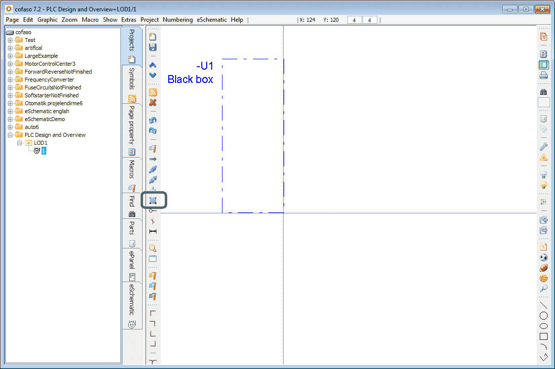
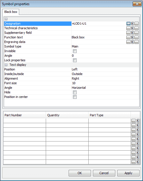
Use the “Insert Black Box” button to draw a box on the page. You left-click and hold the mouse button at the top left corner and then position your mouse to the bottom right corner of the box and release the mouse button. This will draw the box.
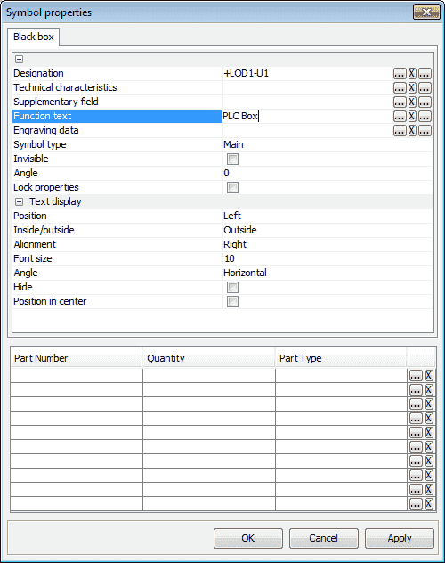
The symbol properties window for the black box will now be displayed. Enter the Function test name as PLC Box. Select OK.
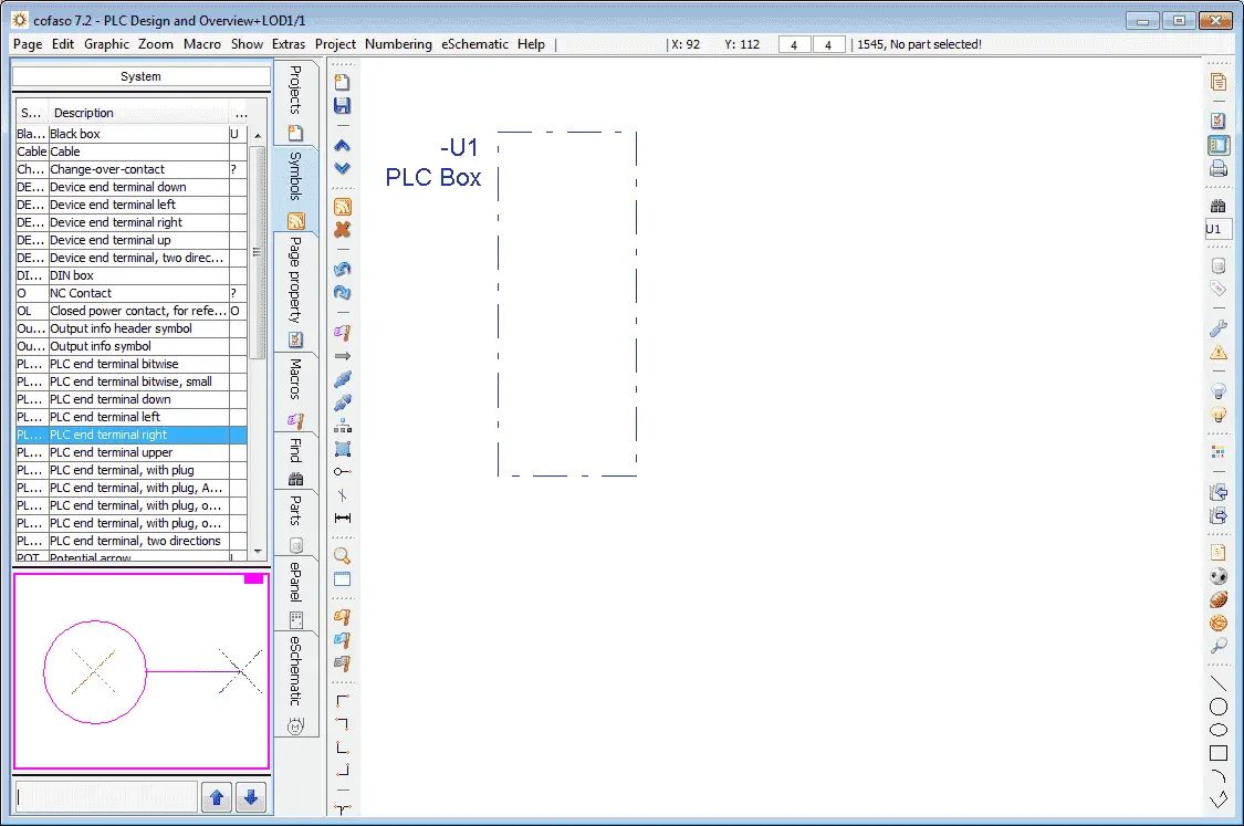
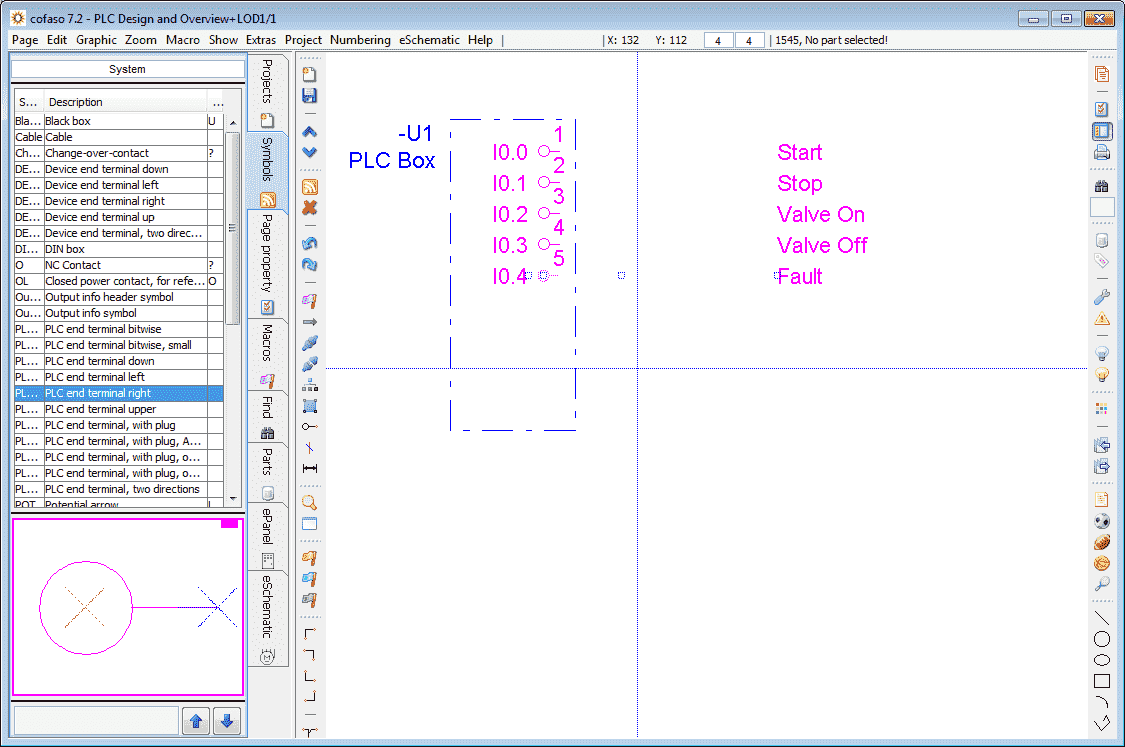
Under the Projects tab select Symbols. In the list of symbols select “PLC end terminal right”
Position the PLC to end terminal right point in the PLC Box that we created and left-click the mouse button.
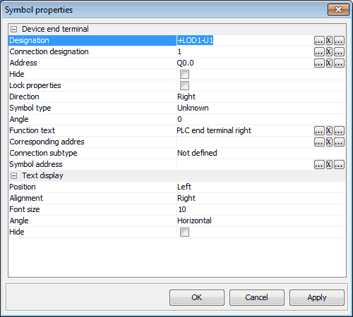
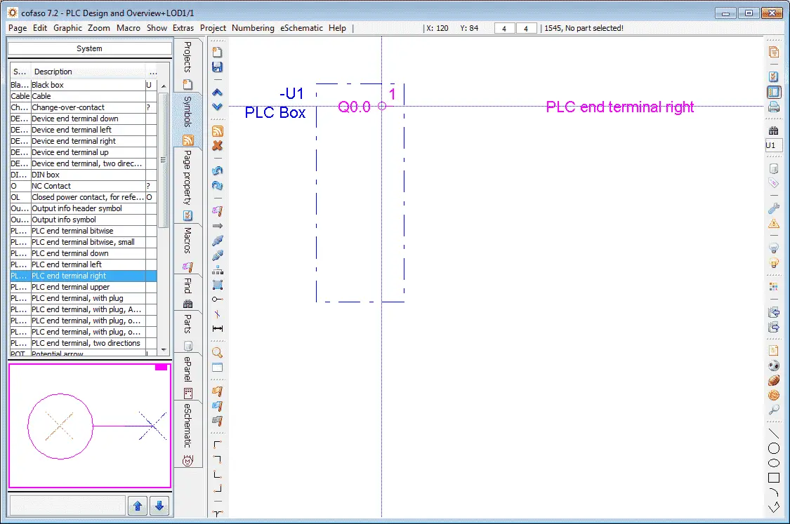
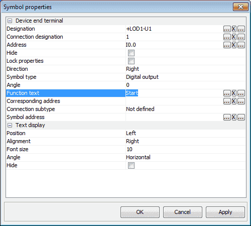
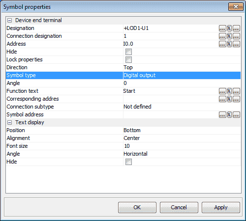
Our symbol properties window will now appear. Change the Address to I0.0. Select the symbol type as Digital output. We will also name our first terminal Start.
Select OK.
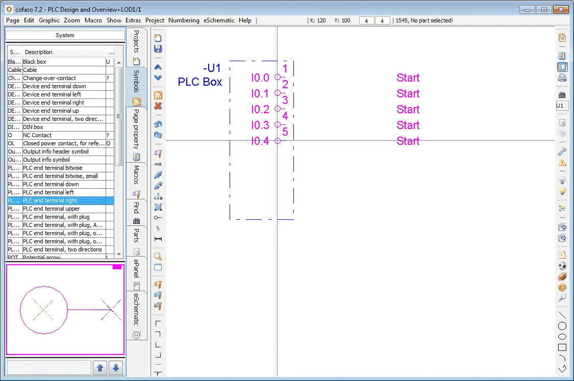
We can now add four additional terminal points. Use the left mouse click to click where the next point will be located. The address of each point will automatically be incremented. Hit the ESC key on the keyboard to stop the inserting of the terminal numbers.
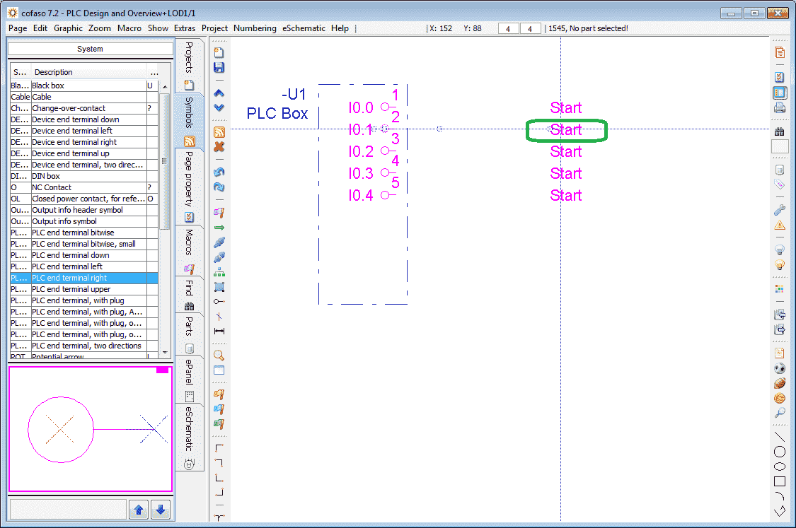
Double click on the second Start text. This represents the I0.1 terminal 2.
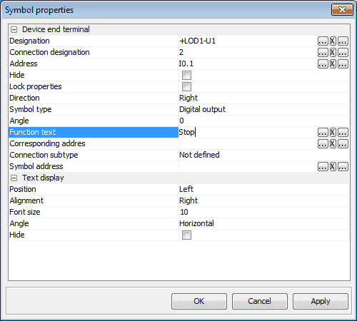
Under the symbol properties, we can change the function text to Stop. Hit OK to return to our drawing.
We can now repeat the above procedure for the other terminal names.
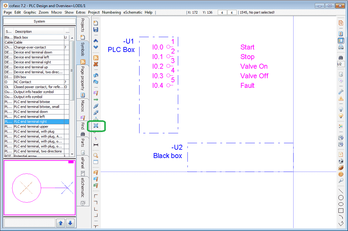
Draw another black box using the insert black box icon.
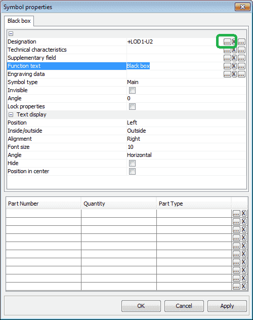
We will leave the default name of Black Box. Select the menu button (…) beside the designation.
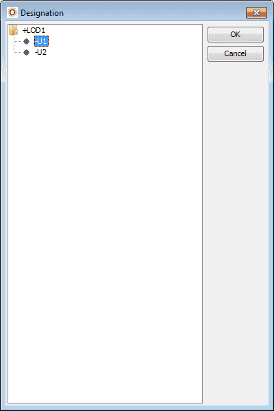
Select -U1 which is the same as our PLC Box that we created earlier. Hit OK.
You will now see that our Designation is the same for both boxes. Hit OK.
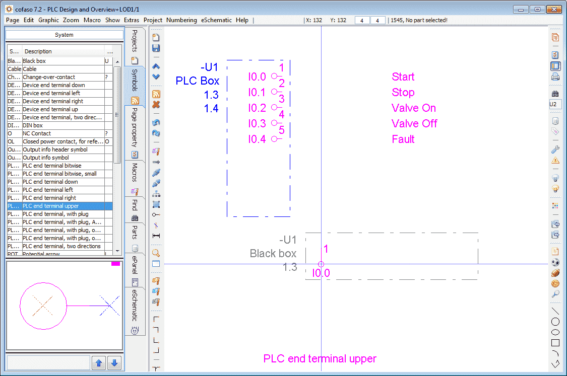
Under the symbols, select PLC ends terminal upper. Position the terminal on the Black box that we just created and left mouse click.
Our symbol properties window will now be displayed. Ensure that the symbol type is Digital output. This is the same as our PLC Box. Hit OK.
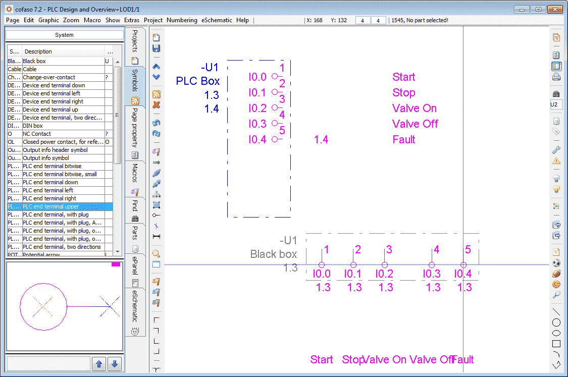
We can now click for each of the terminals on the Black Box. You will notice that the addresses will automatically be incremented and the text will match the connections in the PLC Box. We have now finished our terminal drawing.
Device End Terminal Plan
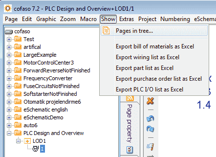
Under the main menu select Show and then Pages in tree…
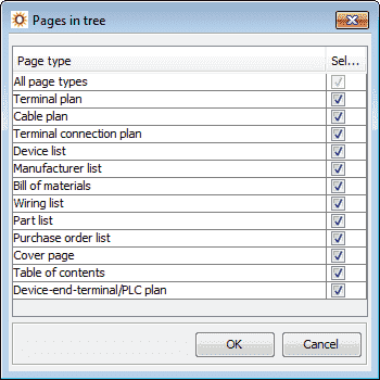
Deselect all but Device-end-terminal/PLC plan.

Select OK.
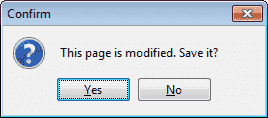
A confirmation message will be displayed to save the project. Select Yes.
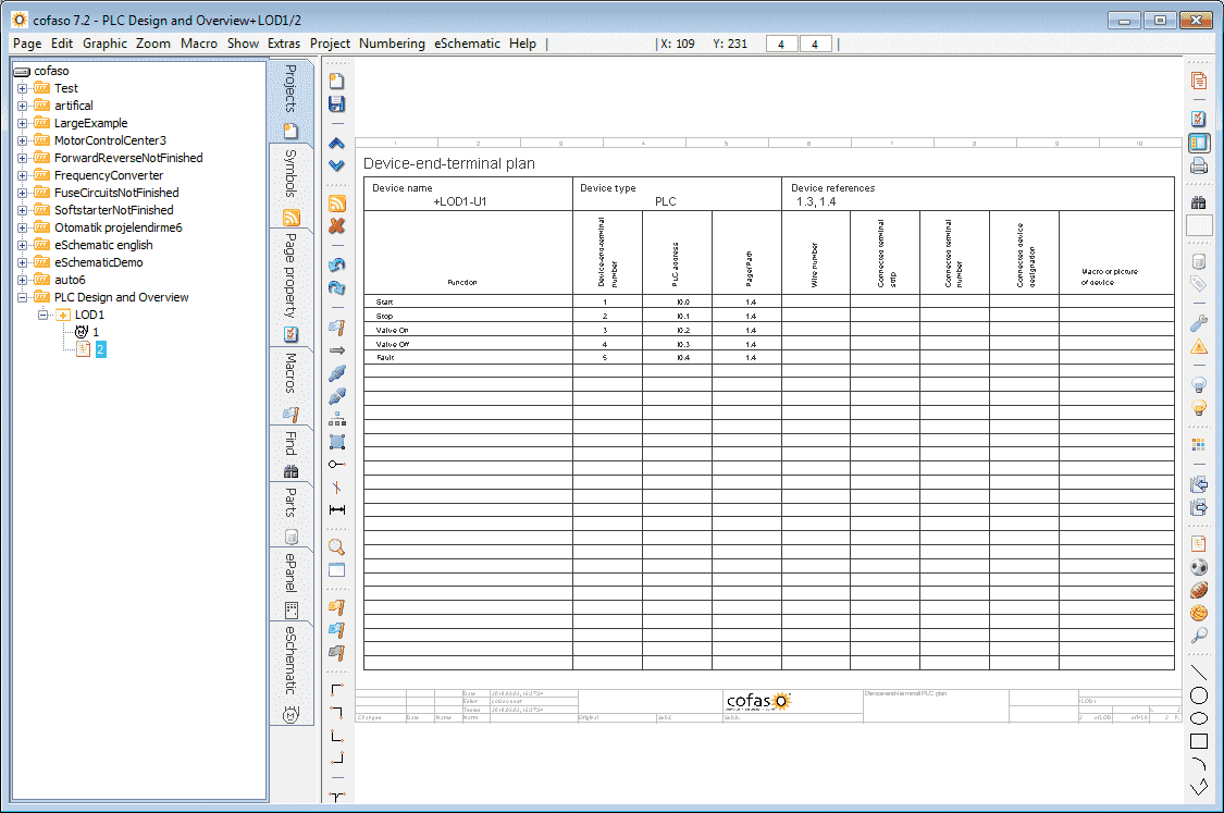
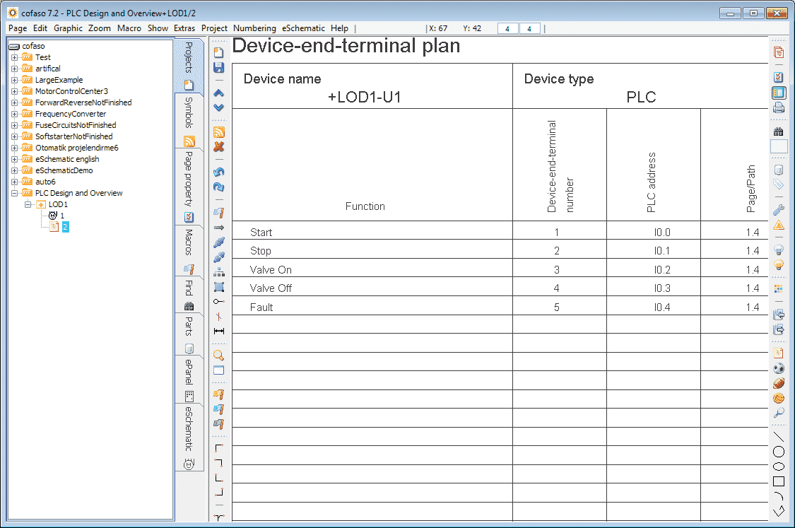
A chart of the terminals that we programmed is presented.
Modifications of drawings happen all of the time. This time-consuming task can be simplified using Cofaso 7.
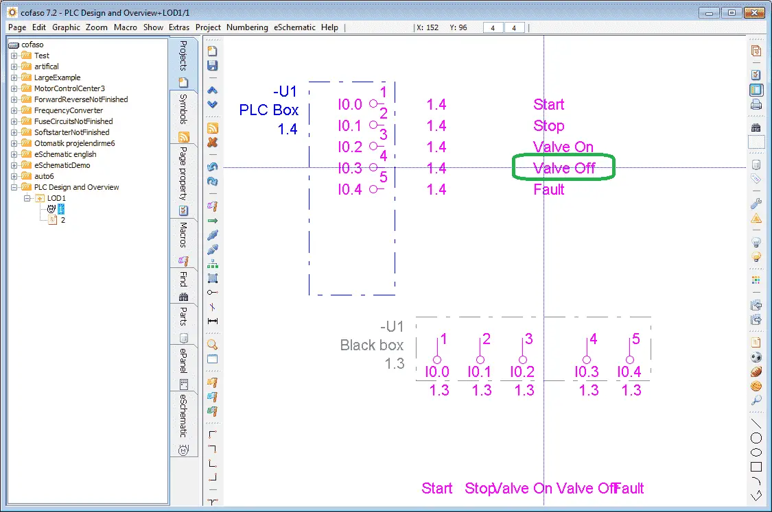
Select our original drawing and double click on the Valve Off text.
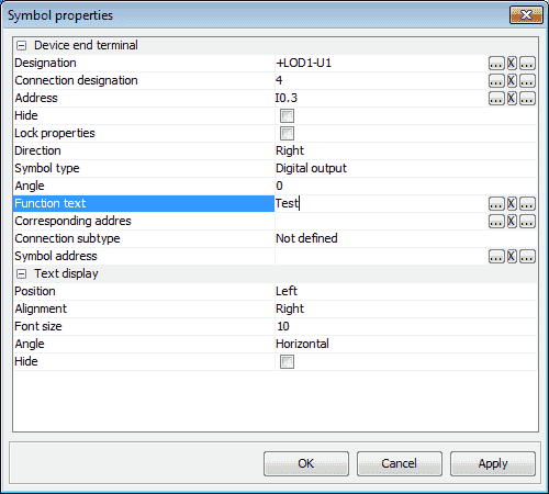
Change the name to Test. Click OK.
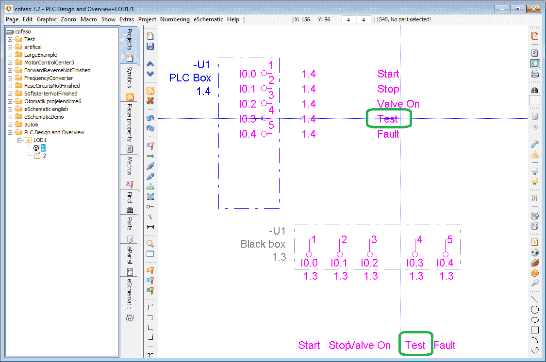
Notice that the name is now changed on all of the locations of our drawing(s).
Select page 2, which is our Device-end-terminal plan.
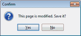
A notification is given indicating that the page is modified and if we would like to save it. Select Yes.
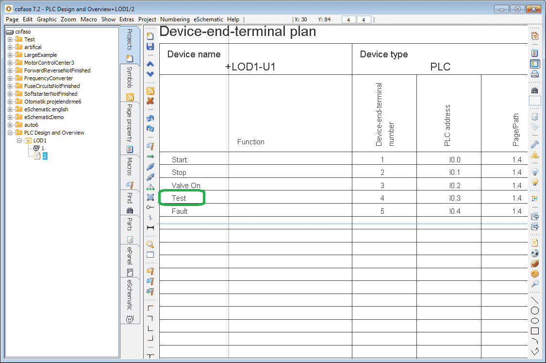
Notice that the name Test is also changed on the device end terminal plan.
Watch the video below to see the above steps in action.
Cofaso Links and Information:
Website: http://cofaso.com/
Download Free 30 Day Trial:
http://cofaso.com/Download/free-trial/3TCP69OsoyBqiugV-2F-jVI1A-3D–3D-
You will also find additional training videos and information on Cofaso 7.
Computer system requirements:
http://cofaso.com/Support/system-requirements/Z9L9LwRepmpFO-2F-PvymYt-2B-g-3D–3D-
Watch on YouTube: Cofaso 7 PLC Design and Overview
If you have any questions or need further information please contact me.
Thank you,
Garry
If you’re like most of my readers, you’re committed to learning about technology. Numbering systems used in PLC’s are not difficult to learn and understand. We will walk through the numbering systems used in PLCs. This includes Bits, Decimal, Hexadecimal, ASCII and Floating Point.
To get this free article, subscribe to my free email newsletter.
Use the information to inform other people how numbering systems work. Sign up now.

The ‘Robust Data Logging for Free’ eBook is also available as a free download. The link is included when you subscribe to ACC Automation.