Timers are present in just about every PLC program that I have seen. A timing chart is a secret behind understanding the timer that you need in your application. Making a timing chart before writing the program will ensure that all of the information will be accounted for. The secret to using timers is a good review of using these timing charts.
PLC Fiddle has three different timing instructions for us to use in our programs. On-Delay, Off-Delay, and Retentive Timers. We will discuss the timer parameters and the three different instructions. Our timer challenges will help you gain a good understanding of how timers work in the PLC. Let’s get started.
Previously we discussed the free virtual plc simulator called PLC Fiddle and created some challenges. These challenges are ladder logic that you can solve in your browser.
PLC Fiddle Online Editor and Simulator in your Browser – Video
Basic Gate Ladder Logic Challenges
– AND Gate Ladder Logic Challenge Solution
– OR Gate Ladder Logic Challenge Solution
– NAND Gate Ladder Logic Challenge Solution
– NOR Gate Ladder Logic Challenge Solution
– EXOR Gate Ladder Logic Challenge Solution
– EXNOR Gate Ladder Logic Challenge Solution
PLC Fiddle Timer Parameters
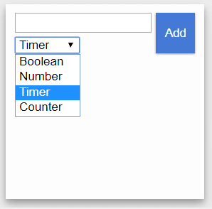
PLC Fiddle will have the variables on the left side of our browser. Select Timer from the drop-down menu.
We can now name our timer variable. Let’s call this “Timer”.
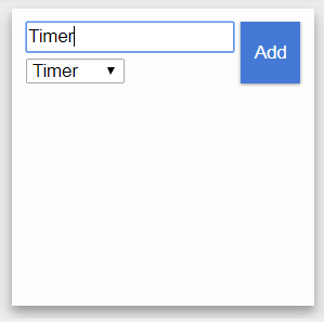
Click Add to add the timer variable to our list.
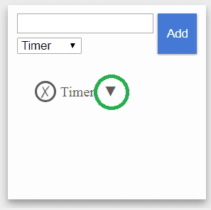
Click the down arrow to see the parameters in the Timer variable.
EN – Enable – This will be on when the timer is energized.
TT – Timer Timing – This is on during the timing of the timer.
Q – Timer Output – This is On when the time has elapsed.
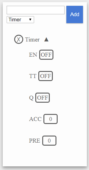
ACC – Accumulated Value – This is the actual value of the timer. (Running Time)
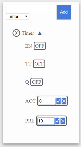
PRE – Preset Value – This is the time that you want the timer to time.
Note: Both of the ACC and PRE settings are in seconds.
PLC Fiddle Timer Instructions

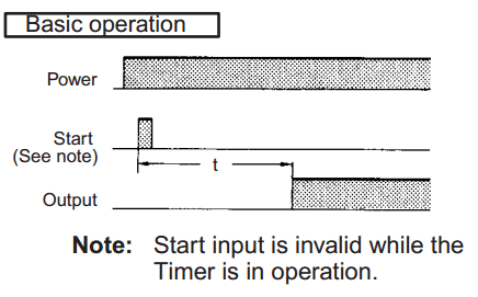
On Delay Timer – When the instruction is energized (logic is true) the accumulator will begin to increment. When the Accumulator is equal to the Preset value the output will turn on. When the instruction logic is false the timer will reset. This means the ACC value returns to 0.
Off Delay Timer – When the instruction is energized (logic is true) the accumulator will remain at 0. When the instruction logic is false (de-energized) the Accumulator will start incrementing and the output turns on. When the Accumulator equals the Preset value the output (Q) turns off.
Retentive Timer – The retentive timer is similar to the On-Delay timer except the Accumulator will only reset with the Reset instruction.
On-Delay Timer Challenge

Take the standard PLC Fiddle latching motor circuit and add an On-Delay Timer to delay the motor start for 10 Seconds. See the above timing chart.
https://www.plcfiddle.com/challenge/bb456921-7112-46d8-9480-dade02c03812
When you are finished with the On-Delay Timer Challenge, click the Check button to test the circuit.
Watch on YouTube: PLC Fiddle On-delay Timer Challenge Solution
Off-Delay Timer Challenge

Add an Off-Delay Timer to the PLC Fiddle latching motor circuit. When the motor turns off, it cannot be started again until 10 seconds elapse. See the above timing chart.
https://www.plcfiddle.com/challenge/a6b3799d-c844-42a4-bcc5-1852b351c09d
When you are finished the Off-Delay Timer Challenge, click the Check button to test the circuit.
Watch on YouTube : PLC Fiddle Off-delay Timer Challenge Solution
Pulse Output Timer Challenge

A lot of PLC will have internal system bits that will pulse for a specific time length on and off. This is often used for flashing lights. We can make this in our browser with PLC Fiddle.
Make a pulse output circuit that will be on for 1 second and off for 2 seconds. See the above timing chart.
https://www.plcfiddle.com/challenge/21cfe08f-1335-47e9-8ffd-79581709f1c8
When you are finished the Off-Delay Timer Challenge, click the Check button to test the circuit.
Watch on YouTube : PLC Fiddle Pulse Output Timer Challenge Solution
Timers are an important part of PLC programming. I hope you found the above timer challenges fun to solve using PLC Fiddle. It demonstrates the basic principles of programming without the investment of equipment. Next time we will look at counter challenge applications.
If you have any questions or need further information please contact me.
Thank you,
Garry
If you’re like most of my readers, you’re committed to learning about technology. Numbering systems used in PLC’s are not difficult to learn and understand. We will walk through the numbering systems used in PLCs. This includes Bits, Decimal, Hexadecimal, ASCII and Floating Point.
To get this free article, subscribe to my free email newsletter.
Use the information to inform other people how numbering systems work. Sign up now.
The ‘Robust Data Logging for Free’ eBook is also available as a free download. The link is included when you subscribe to ACC Automation.

