We will now look at the secret of using timers in the PLC. Timers are used in the majority of PLC programs. There are also a wide variety of off-the-shelf industrial timers that you can use. The implementation of timers can be vast; however, it all starts with a TIMING CHART.
Timing Chart – Secret of Using Timers
A timing chart is the secret behind understanding the timer that you need in your application. Making a timing chart before writing the program will ensure that all information will be accounted for.
The timing chart is mapped out on an x and y plain. The ‘x’ plane will show time. The ‘y’ plain has the state of the input on/off (1 or 0).
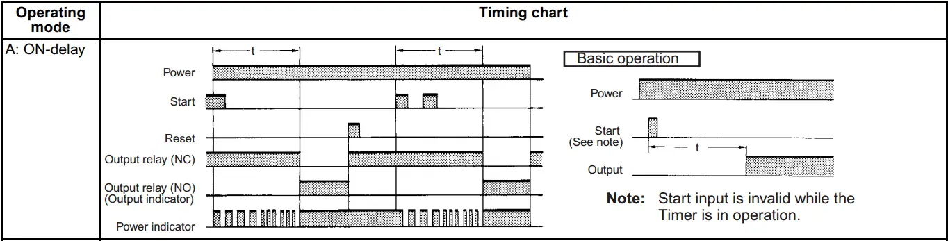
Let’s take a look at a timing chart for an On-Delay Timer. This is the essential operation for an Omron H3BR industrial timer.
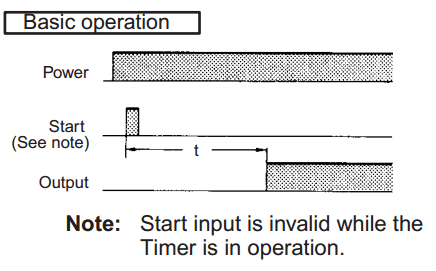
Power – When dealing with PLC, we must consider what happens to the current time and output conditions when power to the unit is removed.
Start – In this case; the start signal is momentary to start the time cycle. (t) We could modify this signal to be maintained until the output switches.
Output – The output will show when it turns on. This can also indicate the opposite and show when it turns off.
Time – The relationship between the start signal and the output shows time. Our example shows timing starts on the leading edge of the Start. This could have also been on the trailing edge.
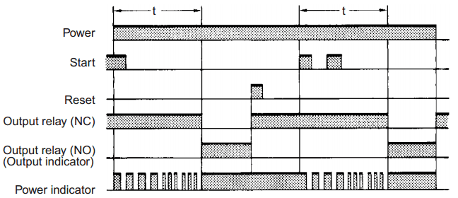
Here is the same on-delay timing chart with some more detail. Several conditions are added to the chart.
Questions to Ask – Secret of Using Timers
These conditions prompt us to ask the following questions.
What happens when:
- Power is removed/restored
- Multiple start signals are received
- Do we need a Reset signal? If so, what happens during its operation
- Do we need a display of the time? Present Value (PV) / Set Value (SV)
As you can see, the timing chart is vital in determining how the sequence will be performed. This is the same method I use when determining timing sequences in a PLC program.
Let’s look at an example.
When we hit the start button, the warning light then comes on. After a fixed time, the warning light goes off, and the motor starts. The motor will run until the stop button is hit.
We will start by using the Start / Stop Circuit we did earlier.

You will notice that we have added an internal memory bit (C0) as our Start Sequence. This is a memory retentive bit, so we can use the (ST0) $FirstScan to make this circuit non-memory retentive. The circuit does not remember the last state if the power goes off or the PLC is put into program mode. It will default to be off.
The sequence is as follows:
- Start pressed
- TMR starts to time (10 seconds)
- Warning output comes on
- After TMR (10 seconds)
- Warning output goes off
- Motor output comes on
- Stop pressed
- TMR is reset to 0
- Warning light off
- Motor is off
Every PLC has timers. They all have different types depending on what you are trying to achieve. It will all start with your Timing Chart.
Watch on YouTube: Learn PLC Programming – Free 8 – The Secret of Timers
If you have any questions or need further information, please get in touch with me.
Thank you,
Garry
If you’re like most of my readers, you’re committed to learning about technology. Numbering systems used in PLCs are not challenging to learn and understand. We will walk through the numbering systems used in PLCs. This includes Bits, Decimals, Hexadecimal, ASCII, and Floating Points.
To get this free article, subscribe to my free email newsletter.
Use the information to inform other people how numbering systems work. Sign up now.

The ‘Robust Data Logging for Free’ eBook is also available as a free download. The link is included when you subscribe to ACC Automation.