We will now be looking at using digital inputs (pushbuttons) to turn LEDs on and off. This will be programmed using our Arduino Uno R3 from our Super Starter Kit. Pushbuttons will allow actions to be performed that our Arduino program sketch will interpret and take action.
We will be wiring two pushbutton switches. A pull-down resistor will be wired to the first switch and a pull-up resistor will be wired to the second switch. This will change the state of the input (High (1) or Low (0)) based on the wiring. Two LEDs will be wired to the outputs of the Arduino Uno. This will show the state of the switches and allow the switch inputs to modify the state of the LED. We will look at three different programs.
Eliminating switch bouncing will also be discussed and programmed using our Arduino Uno super starter kit. Let’s get started.
A full list of posts in this series can be obtained at the following location:
Arduino Uno Software Super Starter Kit
Previous posts in this Arduino Uno Super Starter Kit Series:
Hardware and Powering – Video
Software – Video
LEDs – Video
Watch the video below of the operation of digital inputs with our Arduino Uno Kit. Elegoo Super Starter Kit UNO R3.
Switches
Switches are simple mechanical devices that will connect two contacts together with a press of a button or flip of a lever.
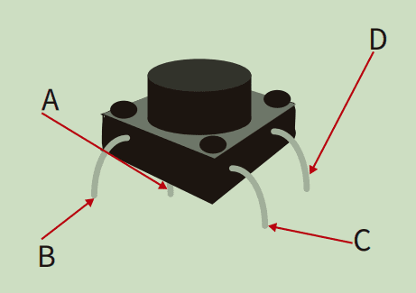
This is the drawing of the switch that we will be wiring.
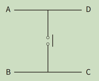
The four connections can be confusing, but you can see how they are connected internally. A, D, and B, C, are connected internally. When the switch is pressed, A, D, will connect to B, C.
Wiring Switches to Arduino Uno
The way in which we wire the switch will determine the normal (Nothing is pressed.) state of the input pin of our Arduino.
Resistors are used to limit the current to our Arduino pin. The placement of the resistor in our circuit will determine the state of the input.
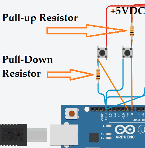
The pull-up resistor connects to the +5VDC and then to one side of the switch. This is also connected to the input pin. The other side of the switch is connected to GND. The switch in its normal state has + voltage to the input pin. The pin state is high. (On or 1) If the switch is pushed, this will create a circuit to GND. The input state will then be low. (Off or 0).
The pull-down resistor connects to the GND and then to one side of the switch. This is also connected to the input pin. The other side of the switch is connected to +5VDC. The switch in its normal state has 0 voltage (GND) to the input pin. The pin state is low. (Off or 0) If the switch is pushed, this will create a circuit to +5VDC. The input state will then be high. (On or 1).
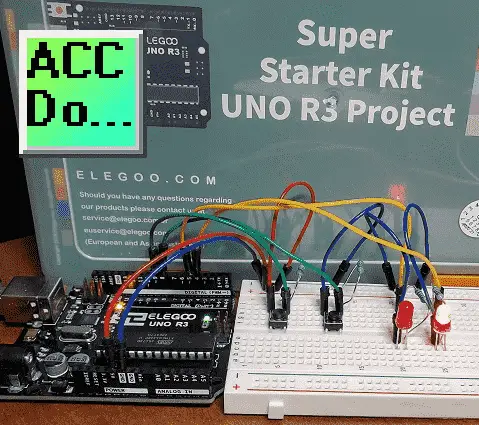
Arduino Uno Switch and LED Wiring
Here is our wiring circuit.
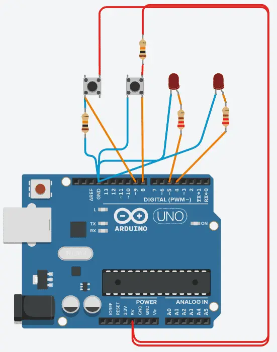
The resistors are 10K ohms for the pushbutton switches and 220 ohms for the LEDs.
Last time we discussed ohm’s law and how to calculate the current in our circuit.
Here is an online ohm’s law calculator. Using the ohm’s law online calculation you can see that the current going through the switch is (I = V/R = 5/10000) 0.0005 ampere (A) or 0.5 milliampere (mA).
Arduino Program Sketch for Input Switch State
The following program sketch will follow the state of the input switch to the output LED.
/*-----( Import needed libraries )-----*/
/*-----( Declare Constants and Pin Numbers )-----*/
int buttonApin = 9;
int led5Pin = 5;
int buttonBpin = 8;
int led4Pin = 4;
/*-----( Declare objects )-----*/
/*-----( Declare Variables )-----*/
void setup() /****** SETUP: RUNS ONCE ******/
{
 pinMode(buttonApin, INPUT);
 pinMode(led5Pin, OUTPUT);
 pinMode(buttonBpin, INPUT);
 pinMode(led4Pin, OUTPUT);
}
void loop() /****** LOOP: RUNS CONSTANTLY ******/
{
if (digitalRead(buttonApin) == HIGH) {
 digitalWrite(led5Pin, HIGH);
} else {
 digitalWrite(led5Pin, LOW);
}
if (digitalRead(buttonBpin) == HIGH) {
 digitalWrite(led4Pin, HIGH);
} else {
 digitalWrite(led4Pin, LOW);
}
}
Download the program to the Arduino Uno.

As the program is running, the LED’s will follow the state of the input push switch. Switch 9 (LED Pin 5) will be normally off (Pull-down Resistor). When the switch is pushed, LED 5 will turn on.
Switch 8 (LED Pin 4) will be normally on (Pull-up Resistor). When the switch is pushed, LED 5 will turn off.
Watch the video below to see the operation of these pushbuttons on our Arduino Uno controller.
Arduino Sketch Pushbutton Switching LEDs
We will modify our program so that pushbutton switch 9 will turn on LED 5 and turn off LED 4. Pushbutton switch 8 will turn off LED 5 and turn on LED 4.
/*-----( Import needed libraries )-----*/
/*-----( Declare Constants and Pin Numbers )-----*/
int buttonApin = 9;
int led5Pin = 5;
int buttonBpin = 8;
int led4Pin = 4;
/*-----( Declare objects )-----*/
/*-----( Declare Variables )-----*/
void setup() /****** SETUP: RUNS ONCE ******/
{
 pinMode(buttonApin, INPUT);
 pinMode(led5Pin, OUTPUT);
 pinMode(buttonBpin, INPUT);
 pinMode(led4Pin, OUTPUT);
 digitalWrite(led5Pin, LOW);
 digitalWrite(led4Pin, HIGH);
}
void loop()
{
if (digitalRead(buttonApin) == HIGH) {
 digitalWrite(led5Pin, HIGH);
 digitalWrite(led4Pin, LOW);
}
if (digitalRead(buttonBpin) == LOW) {
 digitalWrite(led5Pin, LOW);
 digitalWrite(led4Pin, HIGH);
}
}
Watch the video below to see this switching sketch in action.
Switch Bouncing
When a switch is pressed and the contacts come together they take time to settle into their new position. This settling period can vary. Typically you will see between 1 to 20 milliseconds. To give this some perspective, the human eye can pick up at about 200 milliseconds. This is 10 times slower than the settling in period. To the human eye, this switching is smooth, but it is not. The chattering on the contacts (on-off) can be 1 to 100 times in this settling period. The Arduino Uno scans its code very quickly and can pick up these individuals’ on / off signals from our switch. We were not concerned with the previous code because different switches to turn off and on LEDs were used.
Here is some information on Switch Bouncing and how to prevent it.
Arduino Sketch Pushbutton Toggle Switching
The following sample code has been modified from the following original debounce software code. As you will see this will not decrease the scan (cycle) time of our controller with long delays.
In our example, we will use both the switches to toggle the LED light on and off with each press of the switch independently. We will add some software code in our Arduino to stop the switch bouncing.
/*-----( Import needed libraries )-----*/
/*-----( Declare Constants and Pin Numbers )-----*/
const int buttonApin = 9; // the number of the pushbutton pin
const int led5Pin = 5; // the number of the LED pin
const int buttonBpin = 8;
const int led4Pin = 4;
/*-----( Declare objects )-----*/
/*-----( Declare Variables )-----*/
int led5State = HIGH; // the current state of the output pin
int buttonAState; // the current readingA from the input pin
int lastbuttonAState = LOW; // the previous readingA from the input pin
int led4State = HIGH;
int buttonBState;
int lastButtonBState = HIGH; // Bitton B is the inverse logic
// the following variables are unsigned longs because the time, measured in
// milliseconds, will quickly become a bigger number than can be stored in an int.
unsigned long lastDebounceATime = 0; // the last time the output pin was toggled
unsigned long lastDebounceBTime = 0; // the last time the output pin was toggled
unsigned long debounceDelay = 50; // the debounce time; increase if the output flickers
void setup() /****** SETUP: RUNS ONCE ******/
{
 pinMode(buttonApin, INPUT);
 pinMode(led5Pin, OUTPUT);
 pinMode(buttonBpin, INPUT);
 pinMode(led4Pin, OUTPUT);
 // set initial LED state
 digitalWrite(led5Pin, led5State);
 digitalWrite(led4Pin, led4State);
}
void loop() /****** LOOP: RUNS CONSTANTLY ******/
{
 // Switch A - read the state into a local variable:
 int readingA = digitalRead(buttonApin);
 // check to see if you just pressed the button (LOW to HIGH)
if (readingA != lastbuttonAState) {
 lastDebounceATime = millis(); // reset the debouncing timer
}
if ((millis() - lastDebounceATime) > debounceDelay) {
 // whatever the readingA is at, it's been there for longer than the debounce
 // delay, so take it as the actual current state:
 // if the button state has changed:
if (readingA != buttonAState) {
 buttonAState = readingA;
 // only toggle the LED if the new button state is HIGH
if (buttonAState == HIGH) {
 led5State = !led5State;
}
}
}
 digitalWrite(led5Pin, led5State); // set the LED:
 // save the readingA. Next time through the loop, it'll be the lastbuttonAState:
 lastbuttonAState = readingA;
 // Switch B - read the state into a local variable:
 int readingAB = digitalRead(buttonBpin);
 // check to see if you just pressed the button (HIGH to LOW)
if (readingAB != lastButtonBState) {
 lastDebounceBTime = millis(); // reset the debouncing timer
}
if ((millis() - lastDebounceBTime) > debounceDelay) {
 // whatever the readingB is at, it's been there for longer than the debounce
 // delay, so take it as the actual current state:
 // if the button state has changed:
if (readingAB != buttonBState) {
 buttonBState = readingAB;
// only toggle the LED if the new button state is LOW
if (buttonBState == LOW) {
 led4State = !led4State;
}
}
}
 // set the LED:
 digitalWrite(led4Pin, led4State);
 // save the readingB. Next time through the loop, it'll be the lastbuttonBState:
 lastButtonBState = readingAB;
}
The above Arduino program sketches can be downloaded here.
Watch the video below for the operation of the LED and RGB LED on our Arduino Uno Super Starter Kit.
Elegoo Links:
Service
service@elegoo.com (USA and Canada)
EUservice@elegoo.com (Europe)
Arduino Compatible Links:
Product Hardware
Elegoo UNO Project Super Starter Kit
Elegoo Download Page
Amazon.com
Amazon.ca
Software
– Arduino IDE (Integrated Development Environment)
– Productivity Blocks (Development Timesaver)
– Productivity Blocks Documentation (Wiki)
Community
– Arduino Blog
– Arduino Forum
– Arduino UNO Facebook
Next time we will look at analog inputs for our Arduino Elegoo super starter kit UNO R3.
Watch on YouTube: Arduino Uno Super Starter Kit Digital Inputs
If you have any questions or need further information please contact me.
Thank you,
Garry
If you’re like most of my readers, you’re committed to learning about technology. Numbering systems used in PLC’s are not difficult to learn and understand. We will walk through the numbering systems used in PLCs. This includes Bits, Decimal, Hexadecimal, ASCII, and Floating Point. To get this free article, subscribe to my free email newsletter.
Use the information to inform other people how numbering systems work. Sign up now. The ‘Robust Data Logging for Free’ eBook is also available as a free download. The link is included when you subscribe to ACC Automation.