The MOSAIC Modular Safety Integrated Controller can be programmed for your safety control application. Steps to programming our MOSAIC include writing the program, verification, simulation, downloading and monitoring. Documentation has been included in this controller software that will save you hundreds of hours.
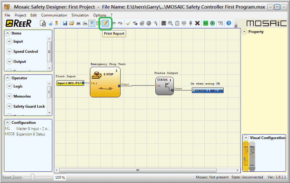
Our first program included writing, verifying, simulating and monitoring our MOSAIC Safety emergency stop switch and status indication. We will now look at the reports and documentation that we can obtain by our Mosaic Safety Designer software (MSD). We will also look at ways that we can verify our existing program. Let’s get started.
Previously in this MOSAIC Safety Controller Series, we have discussed:
MOSAIC Safety Controller System Hardware
– System Hardware Un-boxing Video
– System Hardware Powering Up Video
Installing the Software (MSD) – Video
First Program Part 1 – Video
First Program Part 2 – Video
We will use the program we developed last time.

Note: We will be expanding on this program in later posts to show features of the Safety Controller.
Watch the video below to see the documentation available on the MOSAIC Safety Controller.
The examples and diagrams included in this post are solely for illustrative purposes. Due to the many variables and requirements associated with your particular installation, ACC Automation cannot assume responsibility or liability for actual use based on the examples and diagrams.
Print Single Page – Safety Controller Reports
The print single page will print the program file on one page. This can be used for quickly adding notes in the field to the document.
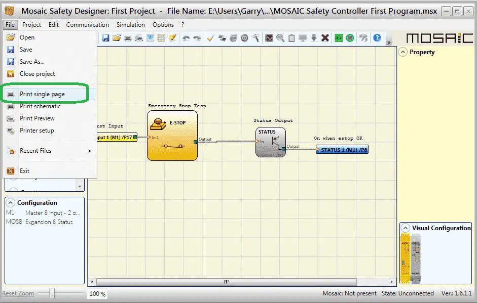
Select from the main menu | File | Print single page
You will then be asked for the printer information and then hit print.
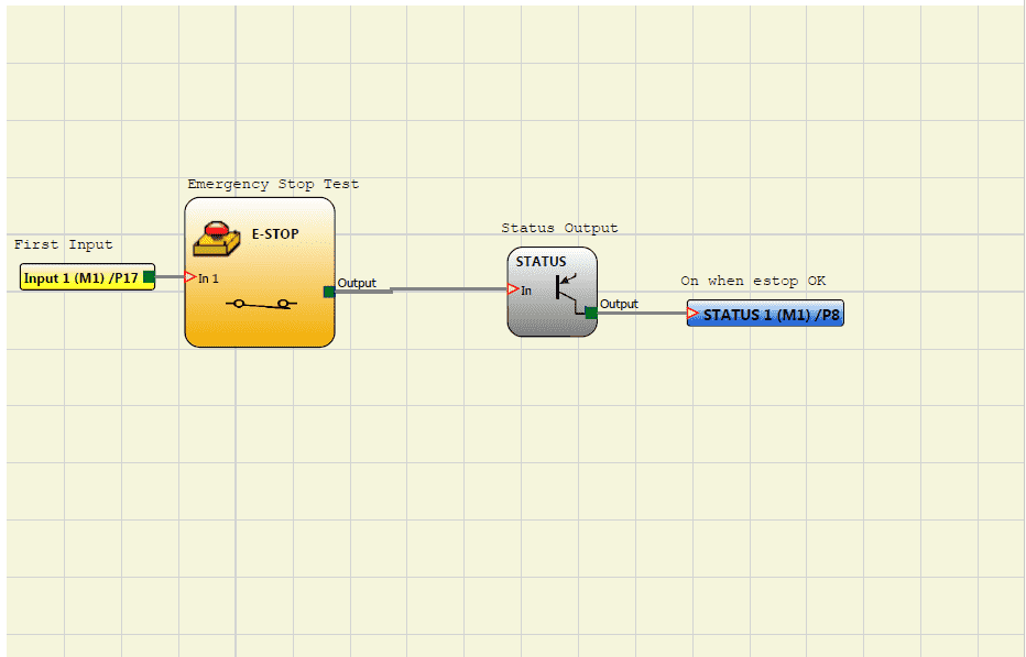
Here is the output from the print single page selection.
Print Schematic – Safety Controller Reports
The print schematic will print the program with an information header and display the Cyclic Redundancy Check number (CRC).
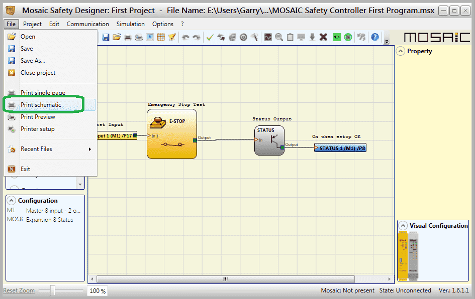
Select from the main menu | File | Print schematic
You will then be asked for the printer information and then hit print.
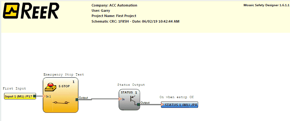
Here is the output from the print schematic. This is part of the documentation for your project.
Note: The CRC number is unique to this program. Any modifications to the program will change this CRC number.
If you print the schematic and receive the following error message, this means that your report might not look correct when printed.
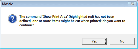
The command ‘Show Print Area’ (highlighted red) has not been defined, one or more items might be cut when printed; do you want to continue?
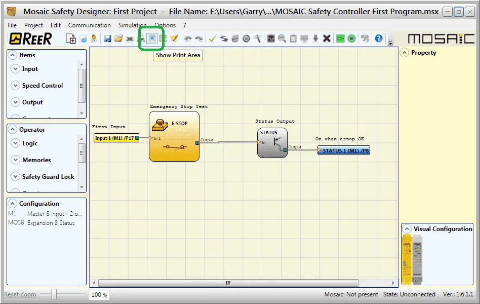
Turn on the show print area from the main menu icons. You can then adjust your schematic so that the print lines for the pages will not interfere with the diagram. In our case, the printout will be fine.
Note: You will not get the warning message if the show print area is enabled before you print the schematic.
Print Report – Safety Controller Reports
Mosaic configuration safety parameters are provided in the MSD (Mosaic Software Designer) software report. Warnings are displayed in the compilation phase and in the report.

Select the print report icon on the main screen.
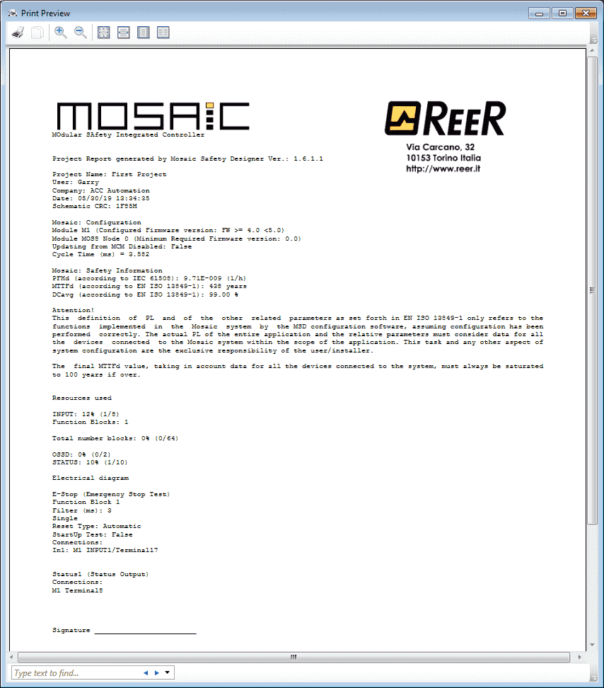
This will display the Modular Safety Integrated Controller (MOSAIC) report in the print preview window. You can then view or print this report.
This report is made up of several sections.

This first section is the title along with the schematic CRC number that we discussed above.

The MOSAIC configuration section is next. It will contain the cycle time of the controller.

MOSAIC safety information values are then displayed.
PFHd – Probability of a dangerous Failure per Hour – This is the random hardware failure value that is used for determining Safety Integrity Levels (SIL).
MTTFd – Mean Time to Failure Dangerous – This value is needed for all equipment that is part of a safety-related control system, in accordance with ISO 13849. Manufacturers of certified sub-systems usually provide PFHd values for their systems.
DCavg – Diagnostic Coverage Average – Measure of diagnostic level (for Input/Logic/Output) – Determined as the ratio between the failure rate of detected dangerous failures and the failure rate of total dangerous failures.
(PFHd according to IEC61508, MTTFd, and DCavg according to ISO13849-1)
Safety Controller Reports Reference Links:
SIL (Safety Integrity) or PL (Safety Performance Level)
Safety Categories, PL and SILs for Machine Safety Control Systems

Hardware resources follow the safety information. This will tell you the number of Inputs, Function Blocks, OSSD and Status items you have used in the M1 safety controller.
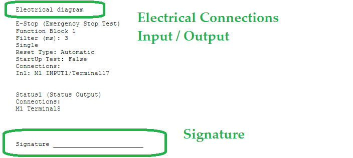
The electrical diagram information and signature is the last items on the report. It will show the pin number of the connections to the M1 safety controller.
This report along with the schematic diagram will provide the necessary documentation for your safety controller.
Verifying the Program in the M1 Controller
If we need to verify the M1 safety controller and have the documentation then we can do this by connecting to the controller via the USB cable.

You will see that we have the Mosaic: Present and the State: Unconnected. Select the connection icon from the main menu.

Since we are reading the program, select Level 1 and hit OK.
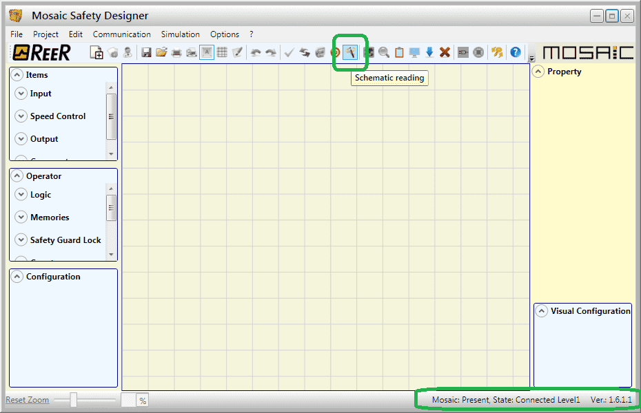
The Mosaic: Present and the State: Connected Level1 will be displayed at the bottom right corner of the window.
Select the Schematic Reading icon from the main menu.

The information window will ask if you are sure that you want to download the schematic from the Mosaic. Select Yes.

The program will now be read from the safety controller.

The program will now be displayed. The CRC check will not be shown until we select the verify (check mark) icon from the main menu.

This will now display our CRC number. Compare this with the number in the documentation to ensure that the program has not been altered/modified.
Select OK.
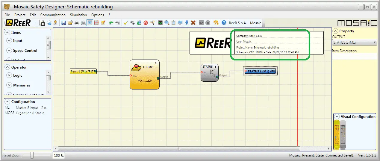
We can now see this CRC number in the heading information.
Watch the video below to see the verification of the program with our documentation on the MOSAIC Safety Controller.
Download the program and sample documentation here.
ReeR MOSAIC Safety Controller (Automation Direct) Advantages:
- Reduces the number of devices and wiring used and overall size of the project
- Speeding-up control panel construction
- Allows tamper-proof system configurations
- All logic is configured through a graphic interface
(no more laborious wiring is needed as with traditional solutions) - The lower number of electromechanical components also means a better performance level and a higher safety level
- The project report provides the actual values of PFH, DCavg, and MTTFd according to EN 13849-1 and EN 62061
ReeR MOSAIC Safety Controller
MOSAIC Controller Installation and Use Manual
MOSAIC Field bus Modules: Installation and Use
Supplemental Communication information and example wiring diagrams
Product Datasheets (Installation and Setup Instruction)
MSD – MOSAIC Safety Designer Software – (Free Download Link) – The software will contain all of the instruction sets and help files for the MOSAIC Safety Controller.
Next time we will be adding to our emergency stop input on the MOSAIC Safety Controller.
Watch on YouTube: MOSAIC Safety Controller Documentation
If you have any questions or need further information please contact me.
Thank you,
Garry
If you’re like most of my readers, you’re committed to learning about technology. Numbering systems used in PLC’s are not difficult to learn and understand. We will walk through the numbering systems used in PLCs. This includes Bits, Decimal, Hexadecimal, ASCII and Floating Point.
To get this free article, subscribe to my free email newsletter.
Use the information to inform other people how numbering systems work. Sign up now.
The ‘Robust Data Logging for Free’ eBook is also available as a free download. The link is included when you subscribe to ACC Automation.

