The MOSAIC Modular Safety Integrated Controller can be programmed for your safety control application. Steps to programming our MOSAIC include writing the program, verification, simulation, downloading and monitoring.
In part 1, we wrote, verified and simulated our program. Our first program has an emergency stop switch with status indication. We will now be using the MOSAIC Safety Designer software (MSD) to download and monitor our program. The wiring and indication lights on our MOSAIC M1 safety controller will also be discussed. Let’s get started.
Previously in this MOSAIC Safety Controller Series, we have discussed:
MOSAIC Safety Controller System Hardware
– System Hardware Un-boxing Video
– System Hardware Powering Up Video
Installing the Software (MSD) – Video
First Program Part 1 – Video
The examples and diagrams included in this post are solely for illustrative purposes. Due to the many variables and requirements associated with your particular installation, ACC Automation cannot assume responsibility or liability for actual use based on the examples and diagrams.
Wiring the MOSAIC M1 – Safety Controller
Last time we programmed our first project.
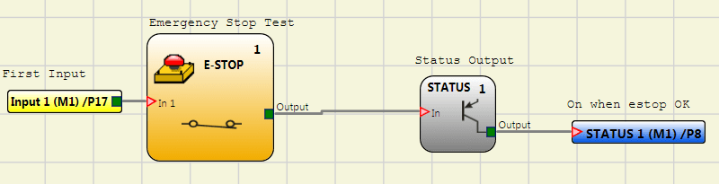
Note: Pin 17 is specified for the input of our E-Stop. Pin 8 is specified for our status output.
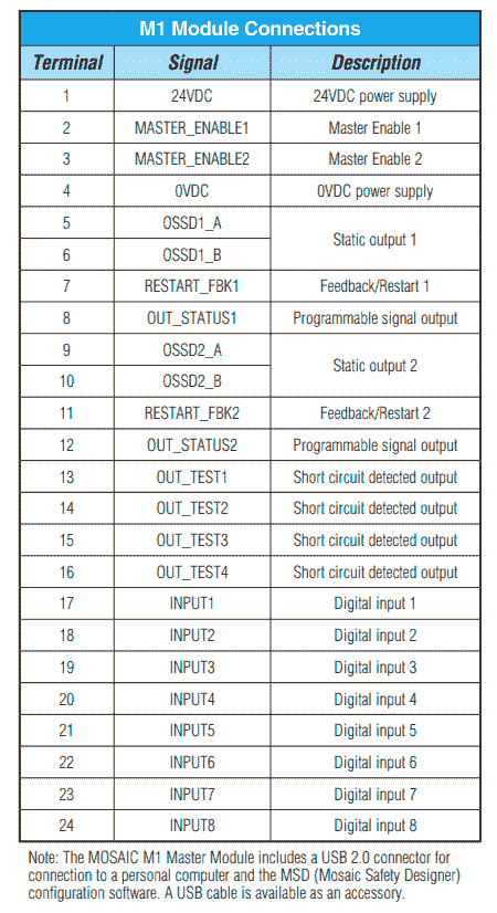
Here are the pin assignments for the MOSAIC M1 Controller.
During the powering up video we applied 24VDC to pin 1 and 0 VDC to pin 4 of each module in our system. Our application now requires that the 24VDC signal be applied to the Master Enable 1 and 2 of the M1.
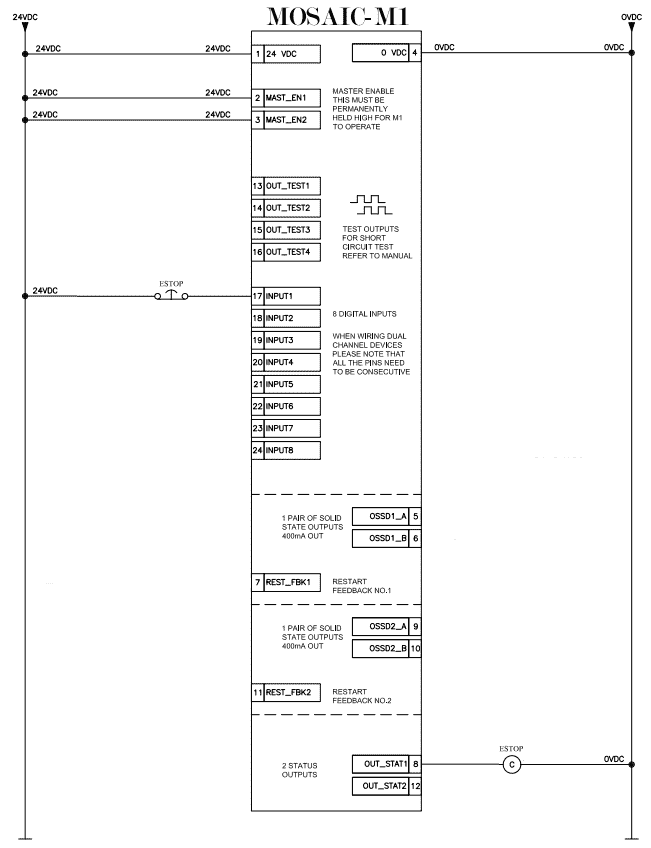
Here is our wiring diagram of the application for the MOSAIC M1 safety controller.
The inputs and outputs are PNP (Positive Switching or Sourcing the load).
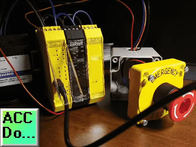
The following components are being used with our MOSAIC Safety Controller system:
AR22V5L-01E3R – Fuji Electric pushbutton, 22mm, twist-to-release, LED illuminated, (1) N.C. contact(s), plastic base, plastic bezel, Operator: red, mushroom, 40mm, round, plastic, 24 VAC/VDC, full voltage.
AR9P719-5A – Fuji Electric legend plate, oversized, aluminum, round, yellow field, yellow background, black engraved text, legend plate marking “EMERGENCY STOP”. For use with 22mm pilot devices.
SA104SL – 22mm pushbutton enclosure, 1 hole(s), 70 x 70 x 74mm (HxWxD), wall mount, thermoplastic ABS, gray body / yellow cover, screw cover.
We have colour coded the wiring for demonstration purposes. Pin 17 is the red wire going to one side of the E-Stop switch. The other side of the E-Stop switch will go to 24VDC. Pin 8 (STATUS Output) is the orange wire that will go to one side of the E-Stop Light. The other side of the E-Stop light will go to 0VDC.
Watch the video below to see the wiring of our first program on the MOSAIC Safety Controller.
Apply power to the safety controller and connect the USB cable.
Start our MSD (MOSAIC Safety Designer) software by double-clicking on the desktop icon or from your windows menu | All Programs | ReeR Mosaic Safety Designer | MSD.
Under the File menu, we can open our First Program.
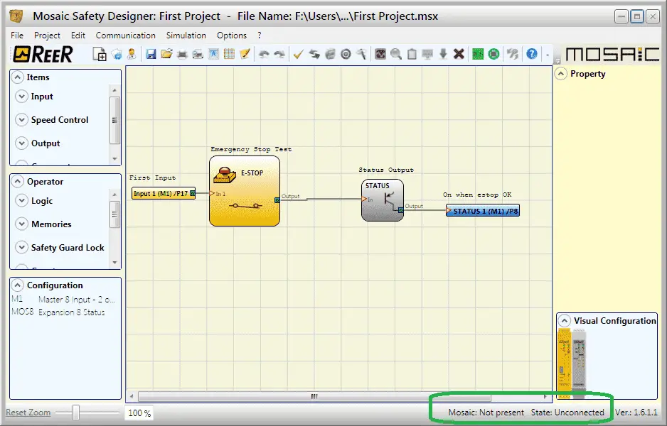
In the bottom right of the screen you will see the following:
Mosaic: Not present – This means that the MOSAIC system is not powered on or the USB cable has not been attached.
State: Unconnected – This will determine if we are connected to the safety controller.
Turn the power on to our MOSAIC Safety Controller and ensure that the USB programming is connected to it and our computer.
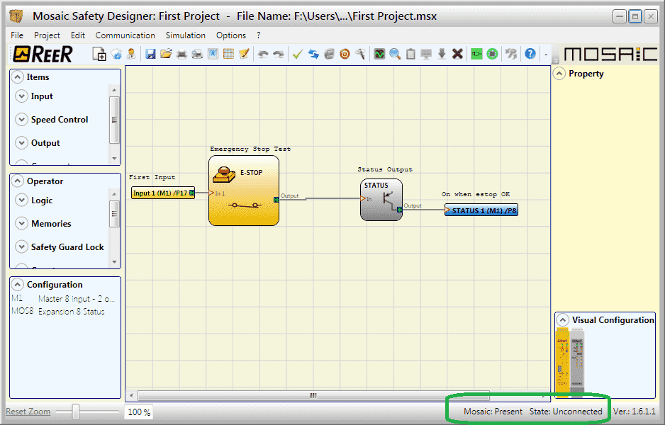
You will now see at the bottom right corner of the screen Mosaic: Present. This means that the controller is powered up and the USB cable is connected.
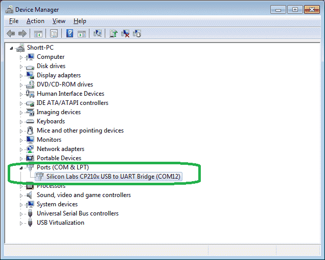
Looking in the Device Manager of windows you will see that the MOSAIC controller uses the USB serial port. In our case, we are using COM12 as the port.
Connect to the MOSAIC Safety Controller
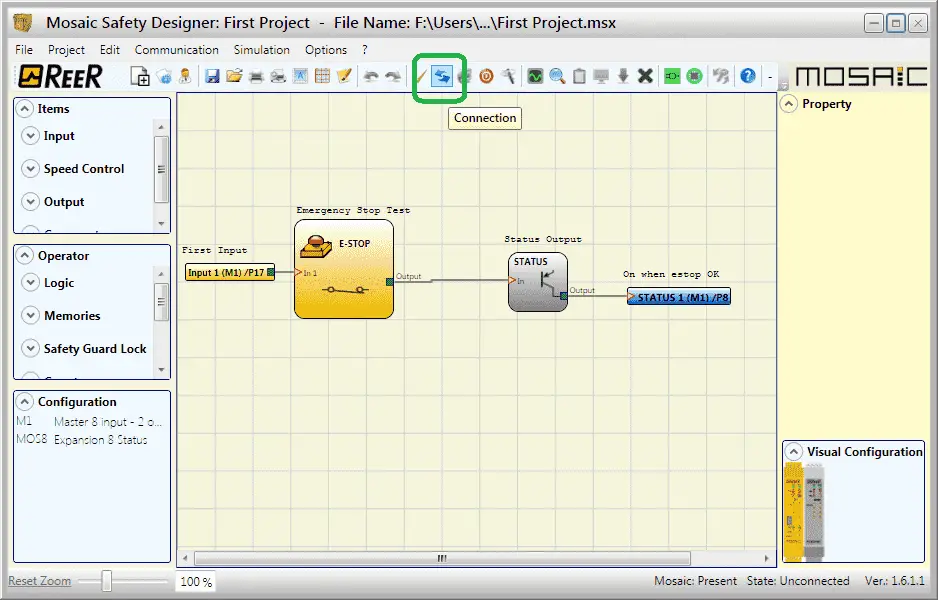
Click the connection icon on the main screen or use the main menu | Communication | Connection.
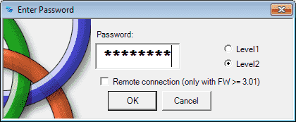
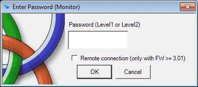
The Enter Password window will be displayed. This is to ensure that we do not want any of our safety devices accidentally changed. Notice that we have Level 1 and Level 2 for our passwords. Since we will be downloading our program we need to ensure Level 2 is selected. (Default) The default password for level 2 is SAFEPASS. This is all capital letters. Select OK.

You will now see that we are now connected to our controller.
Mosaic: Present, State: Connected Level 2
Transfer program to MOSAIC Safety Controller
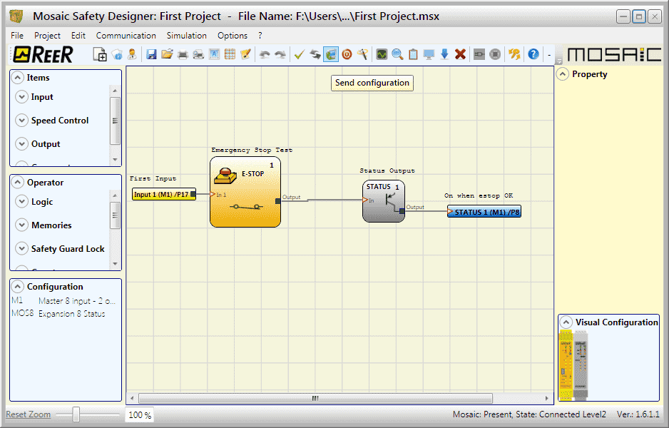
Click the send configuration icon on the main screen or use the main menu | Communication | Send Configuration. The send configuration is the same as sending the configuration and program.
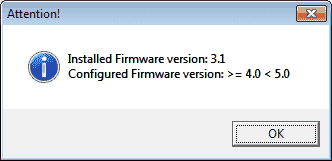
When we programmed the configuration in part 1, we set the firmware at the highest number. This message means that our installed firmware version is 3.1. We must now set this version in our configuration. Select OK.

Click the change configuration icon on the main screen or select from the main menu | Project | Change Configuration.
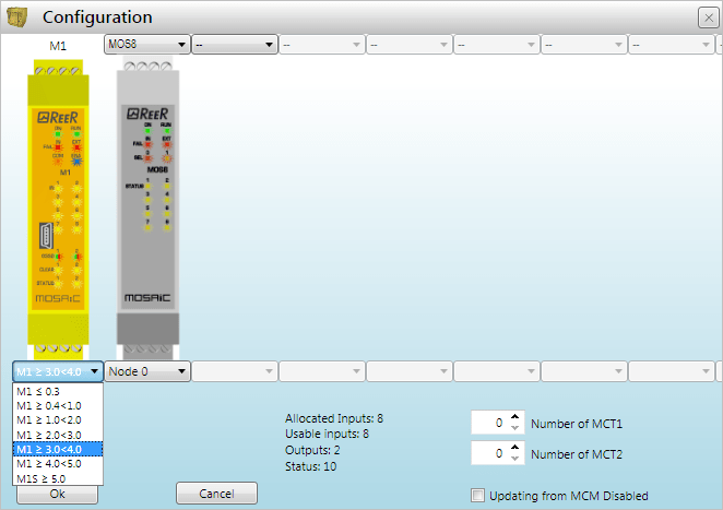
On our configuration window we will select M1 >= 3.0 =< 4.0. Then select OK to change our configuration firmware version.
Now click the send configuration icon again.
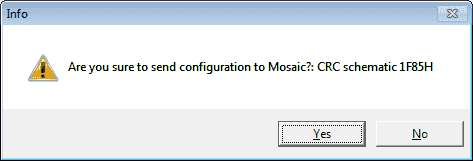
The information window will just confirm with you that we are going to send the configuration and program to our MOSAIC Safety Controller. Select Yes.
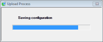
The information will now be sent. This will take approximately 15 to 20 seconds so be patient. It does not appear to matter the size of the program.
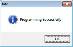
You will now get programming successfully window when the information has finished transferring to the controller. Select OK.
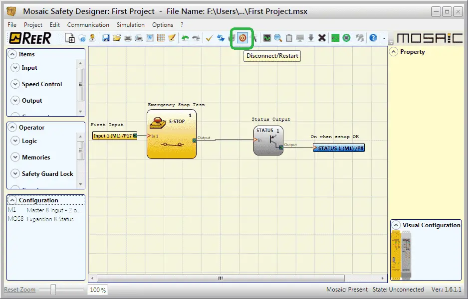
Before the MOSAIC Safety Controller system will start running our program we must disconnect and restart. This is done using the icon on the main screen. You can also use the main menu | Communication | Disconnect/Restart.
Testing the Safety Controller Program
When we cycle our E-Stop button on and off we can monitor the status through the MSD software.
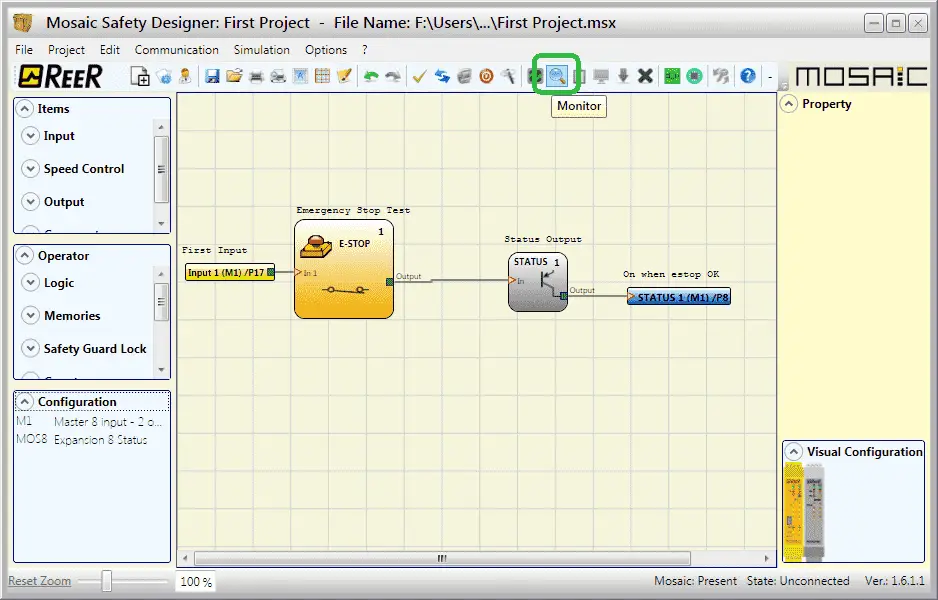
Click the Monitor icon on the main screen or use the main menu | Communication | Monitor.

We must enter our password for Level 1 or 2 in order to monitor our program. Since there is no password set for Level 1 click OK.
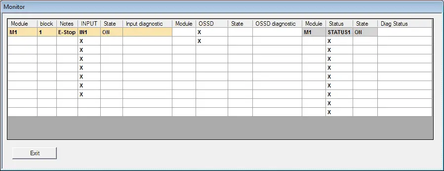
We are now shown a table with the input and output status of the program. In our case, we have just the E-Stop Input and Status Output. Hit the E-Stop button.
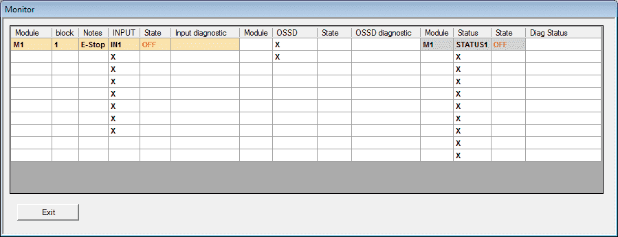
Our E-Stop and Status Output are now off. Click the Monitor icon again to stop our table monitoring.
Graphical Monitor – Safety Controller Program

Click the graphical monitor icon on the main screen or use the main menu | Communication | Graphical Monitor.
We will use level 1, so just select OK to start our monitoring.
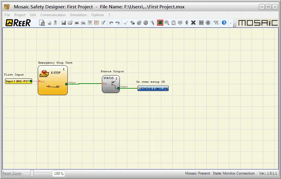
This screen looks similar to our simulator but you will notice that we are connected to the safety controller. Push the E-Stop button.
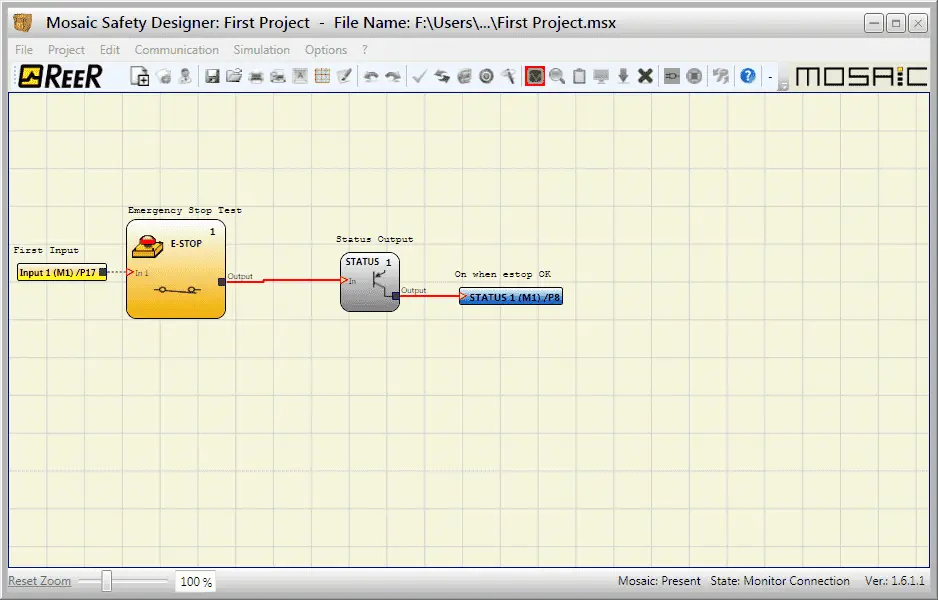
You will now see that our circuit is not activated.
Watch the video below to see the download and monitoring of our first program on the MOSAIC Safety Controller.
Download our first MOSAIC project program here.
ReeR MOSAIC Safety Controller (Automation Direct) Advantages:
- Reduces the number of devices and wiring used and overall size of the project
- Speeding-up control panel construction
- Allows tamper-proof system configurations
- All logic is configured through a graphic interface
(no more laborious wiring is needed as with traditional solutions) - The lower number of electromechanical components also means a better performance level and a higher safety level
- The project report provides the actual values of PFH, DCavg, and MTTFd according to EN 13849-1 and EN 62061
ReeR MOSAIC Safety Controller
MOSAIC Controller Installation and Use Manual
MOSAIC Field bus Modules: Installation and Use
Supplemental Communication information and example wiring diagrams
Product Datasheets (Installation and Setup Instruction)
MSD – MOSAIC Safety Designer Software – (Free Download Link) – The software will contain all of the instruction sets and help files for the MOSAIC Safety Controller.
Next time we will be looking at the reports that are automatically generated from our MOSAIC Safety Controller.
Watch on YouTube: MOSAIC Safety Controller First Program Part 2
If you have any questions or need further information please contact me.
Thank you,
Garry
If you’re like most of my readers, you’re committed to learning about technology. Numbering systems used in PLC’s are not difficult to learn and understand. We will walk through the numbering systems used in PLCs. This includes Bits, Decimal, Hexadecimal, ASCII and Floating Point.
To get this free article, subscribe to my free email newsletter.
Use the information to inform other people how numbering systems work. Sign up now.

The ‘Robust Data Logging for Free’ eBook is also available as a free download. The link is included when you subscribe to ACC Automation.