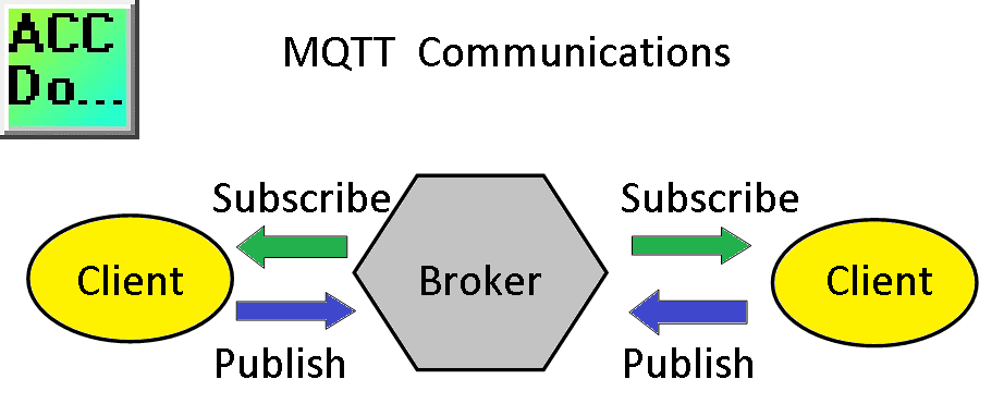
MQTT protocol is used for machine to machine (M2M), internet of things (IoT) communication. This publish/subscribe messaging is used where limited device resources are available or network bandwidth is low. The MQTT protocol provides small size, low power usage, minimized data packets, and efficient distribution of information to one or many receivers.
The Stride MQTT Gateway is an industrial 4.0 hardware component (IIoT – Industrial Internet of Things) that provides isolation and can easily interface with existing Modbus RTU and Modbus TCP communication protocols.
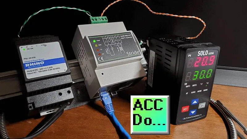
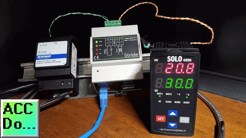
We will be connecting a Stride MQTT Gateway to a Solo process temperature controller via Modbus RTU. (RS485) The MQTT Gateway will communicate to a Mosquitto Broker. Google MQTTLens (MQTT Client) will then read and write to the Solo process temperature controller. Let’s get started.
Previously we have discussed the following for MQTT:
Do-More Simulator MQTT Publish / Subscribe – Video
(Designer Simulator Client – HiveMQ Broker – HiveMQ Client)
BRX Do-More PLC MQTT Communications – Video
(BRX Client – Mosquito Broker – MQTTLens)
Watch the video below to see the MQTT Gateway communicating to our Solo process temperature controller.
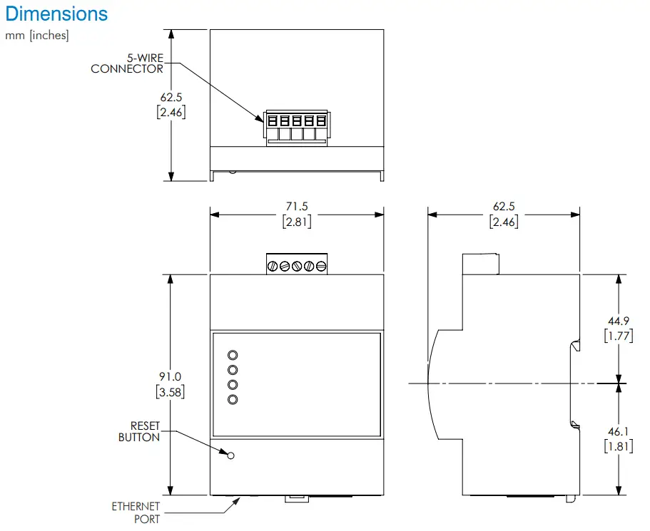
The first thing we will do is open our MQTT Gateway. This gateway will communicate on our existing Modbus RTU (RS485 Serial) and/or Modbus TCP (Ethernet) network. It will then publish or subscribe to the MQTT network using the variables that we set up.
Watch on YouTube: Stride MQTT Gateway Unboxing

Additional information can be found on the MQTT.org website.
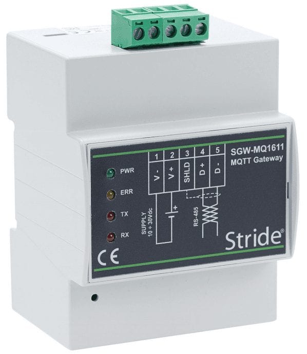
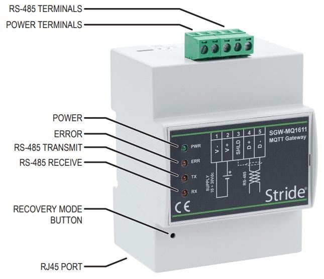
Wiring the Stride MQTT Gateway
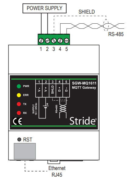
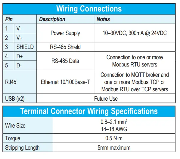
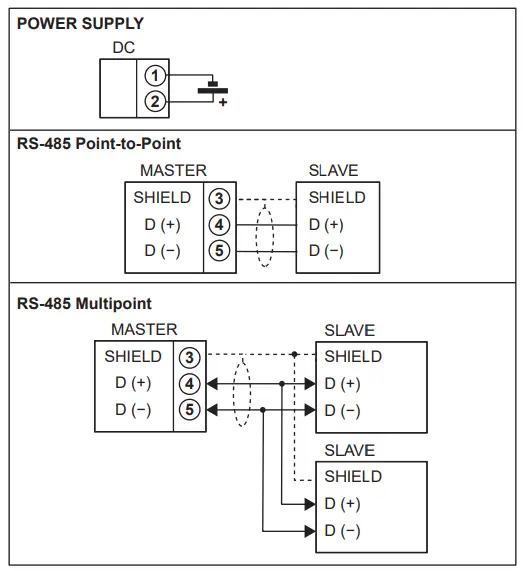

We will be using the Modbus RTU protocol. (RS485) This uses a two-wire serial communication network.
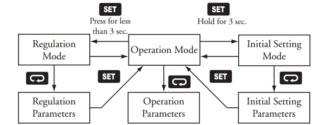
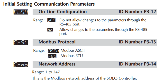
Programming our Solo Process Temperature Controller
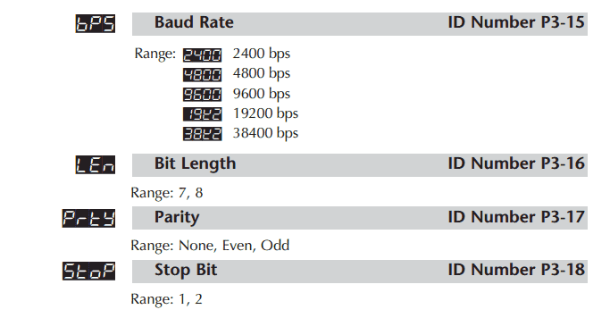
We will be setting up our Solo with the following serial communication specifications: 9600 baud, 8 data bits, 1 stop bit and even parity.
Solo Process Temperature Controller
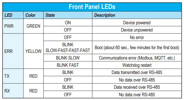
Stride MQTT Gateway Indication Lights
Programming the Stride MQTT Gateway
Connect an Ethernet cable from the unit (RJ45) to the computer. We will be using the Google Chrome Browser to program the gateway.
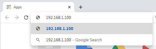
Enter the default IP address.
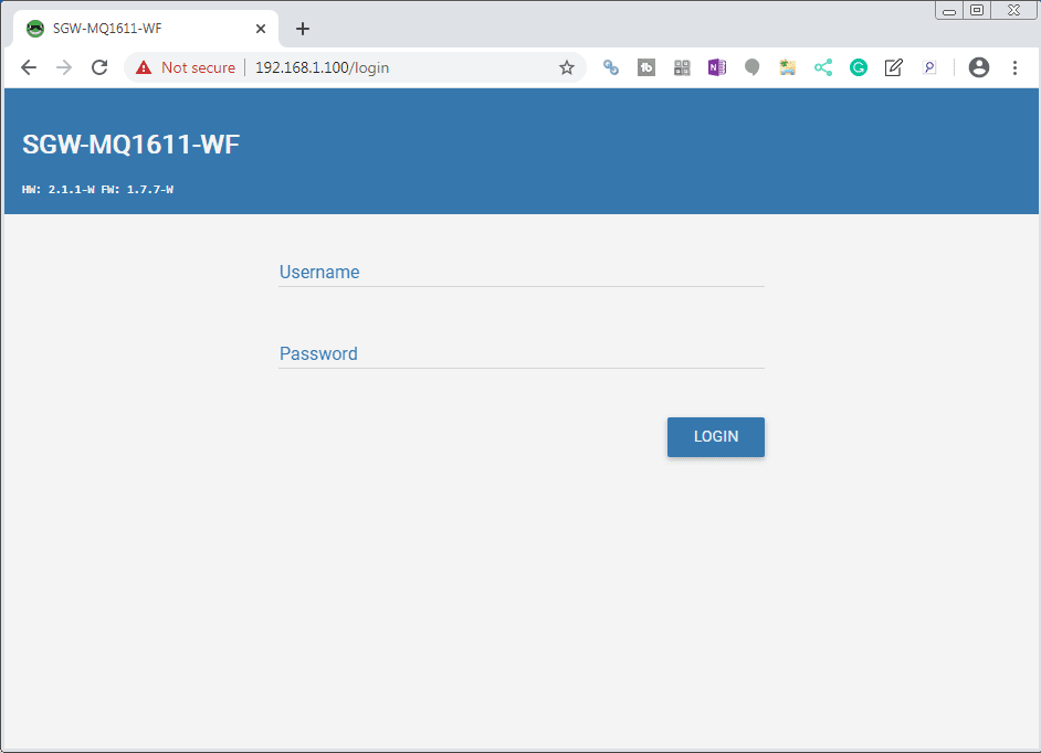
A login screen will now be displayed. Enter the default username ‘admin’ and password ‘password’.
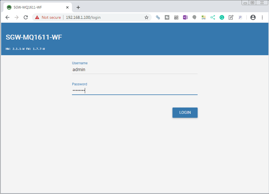
Select the LOGIN button.
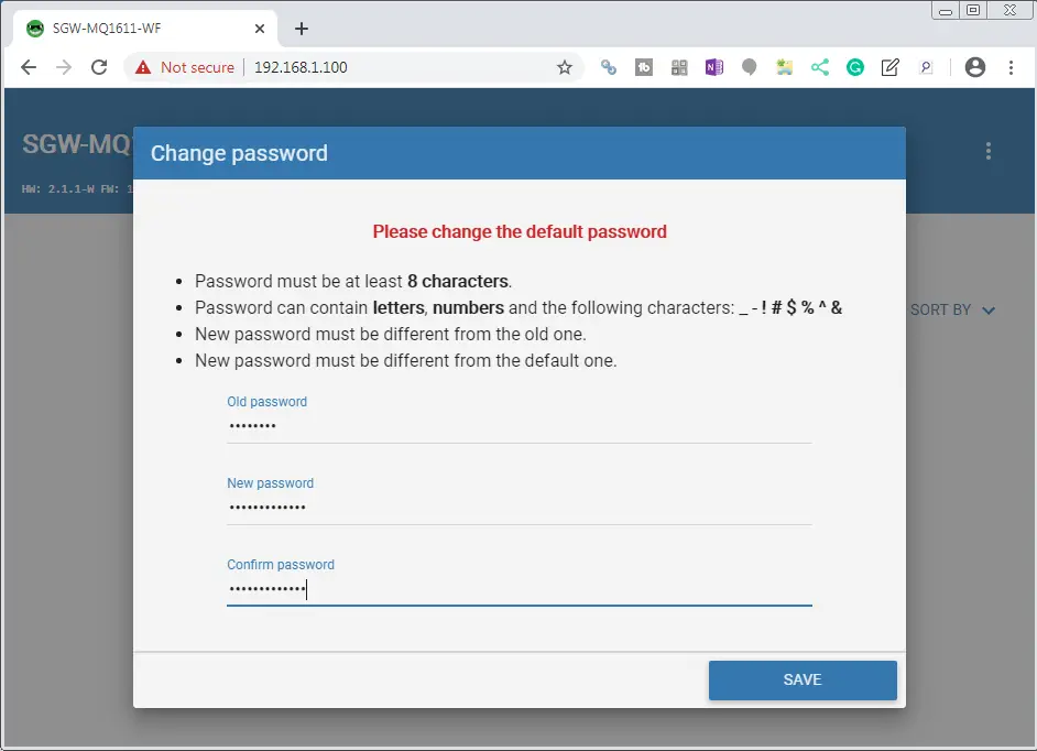
The change password window will now appear since we are using the default password. Enter and confirm a new password. (accautomation)
Select the SAVE button.
Network Interfaces
Select the three dots on the upper right corner of your browser.
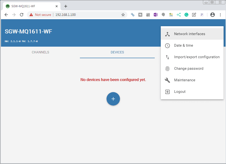
Select Network Interfaces.
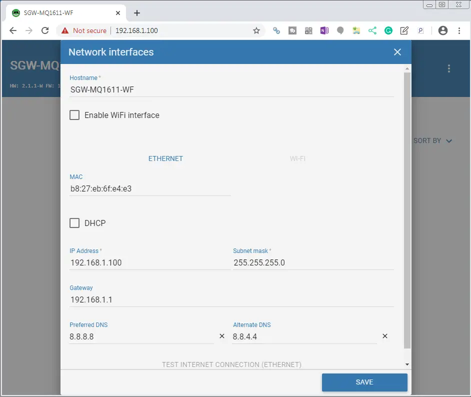
We will leave everything as their default settings except for the preferred and alternate DNS. (Set these to the Google DNS servers)
Select TEST INTERNET CONNECTION (ETHERNET)
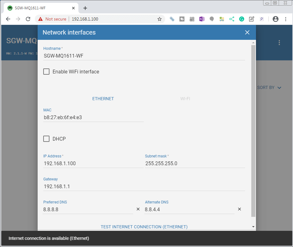
We will get a message at the bottom of the browser indicating that the internet connection is available.
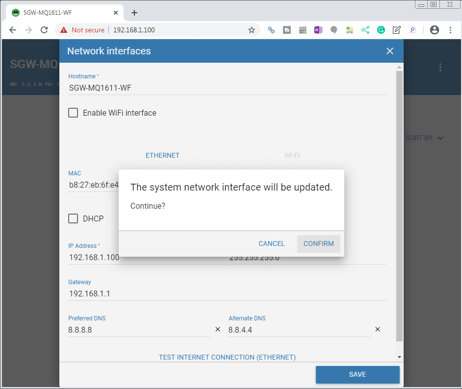
Select SAVE. You will be prompted to confirm the system network interface update. Select CONFIRM.
Channels
Channels are used to set up the Modbus communication parameters.
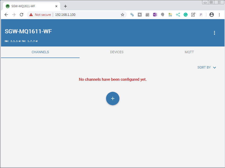
Ensure that you have selected the Channels tab. Select the + symbol to add a channel.
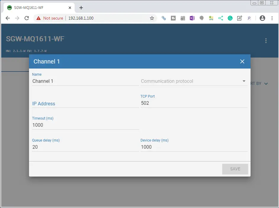
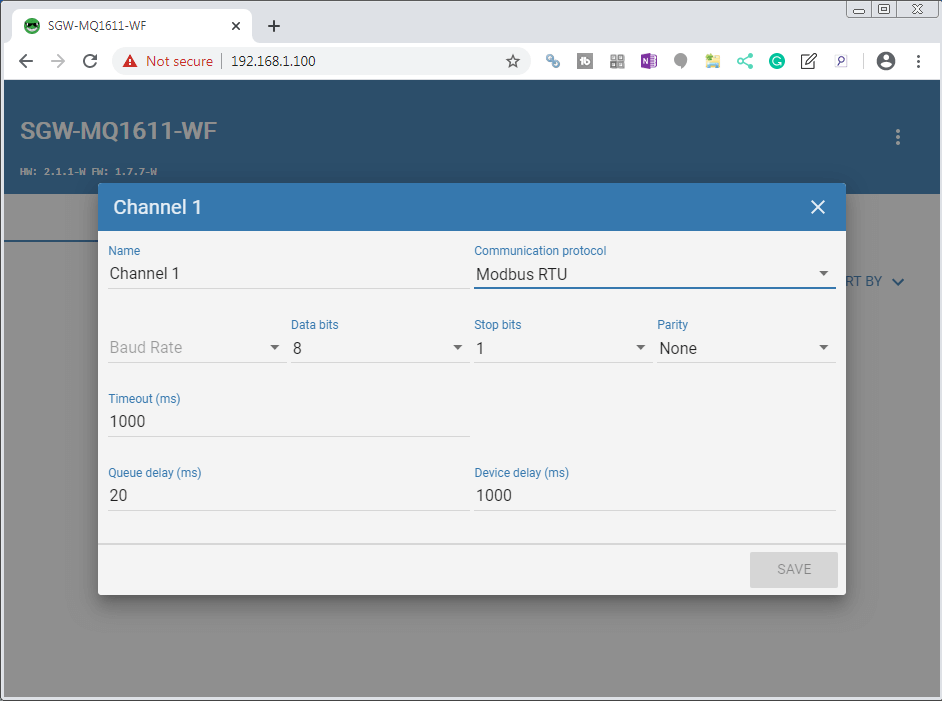
Select the Communication protocol.

You will see that we have three different options. Modbus RTU, Modbus TCP and Modbus RTU over TCP. Select Modbus RTU for our serial communication to the Solo.
Select the Baud Rate of 9600, Data Bits 8, Stop bits 1 and Parity Even. This will match the communication parameters we have in the Solo temperature controller.
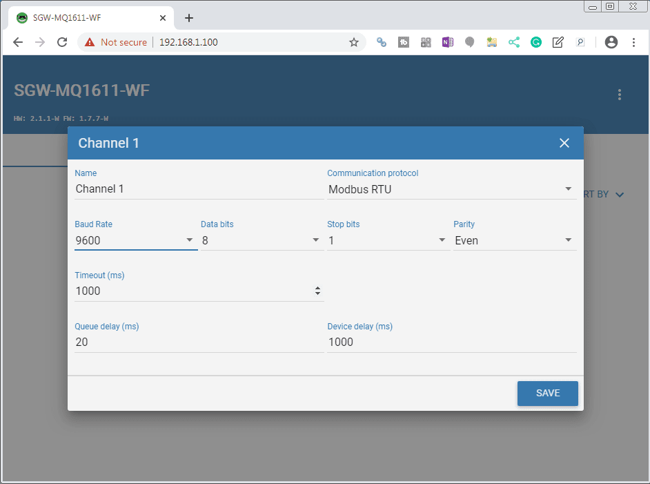
Select SAVE.
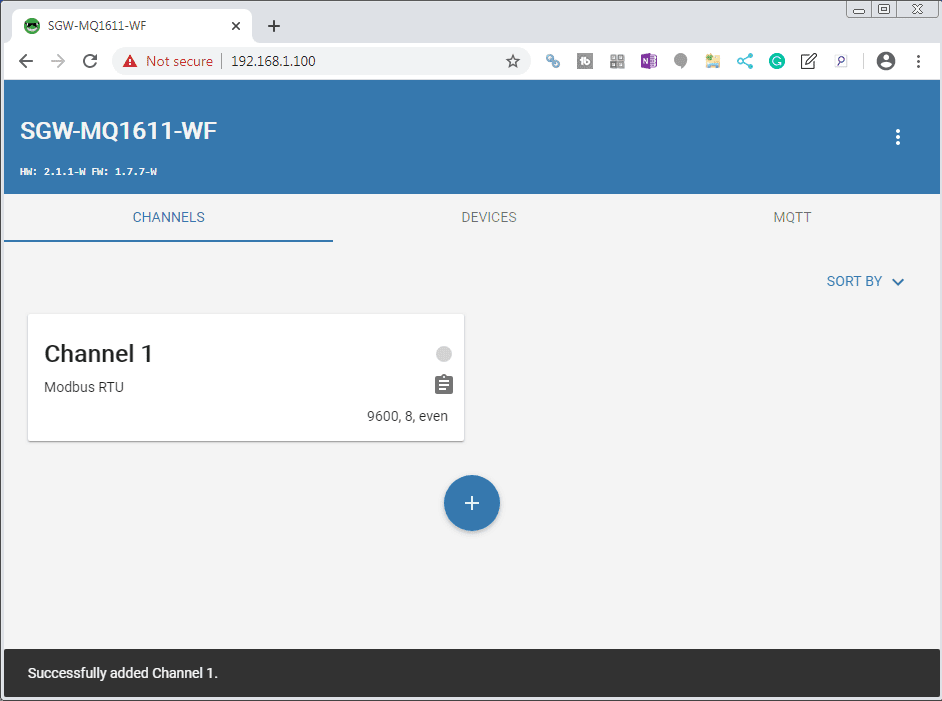
The channel will now be added and you will receive an indication it was successfully added.
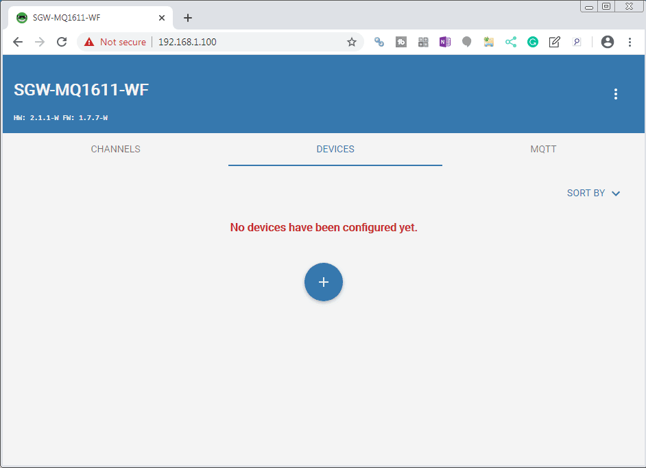
Devices
Devices are used to specify the equipment that is on the channels that we have indicated.
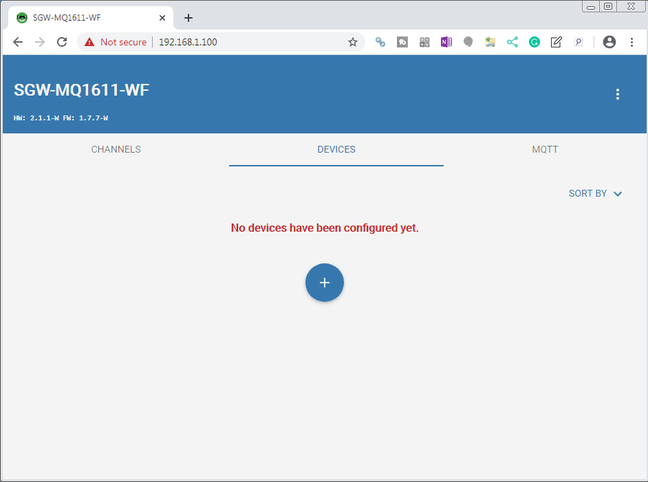
Select the DEVICES tab. Select the + symbol.
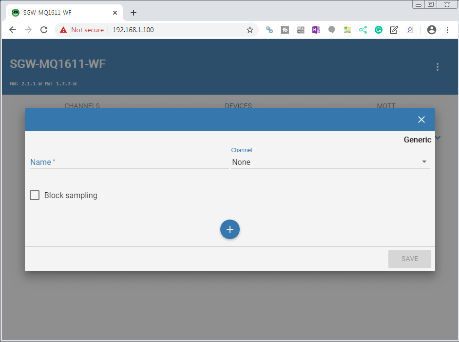
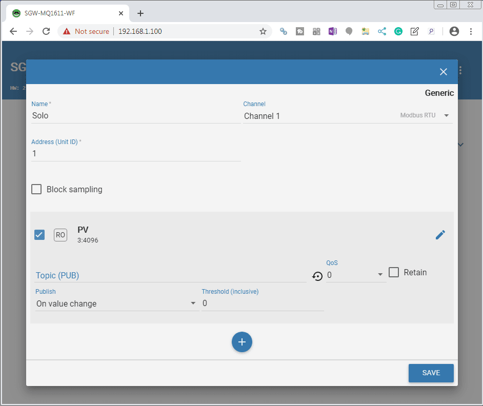
We will name the device Solo. The channel will be set for Channel 1. This will then display the Modbus RTU protocol that we set for the channel.

Select the + symbol.
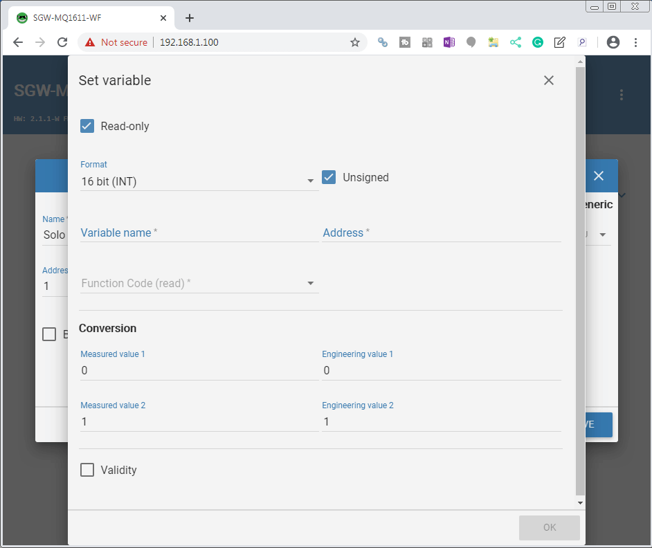
We will now set the variables that we want to read or write.
The variable name will be PV (present value). This is a read-only 16-bit integer. The address for the variable will come from the Modbus address of the Solo.
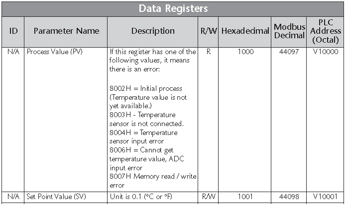
The actual address for the MQTT Gateway will be 4096. We will use the function code of 03 – Read Holding Registers.
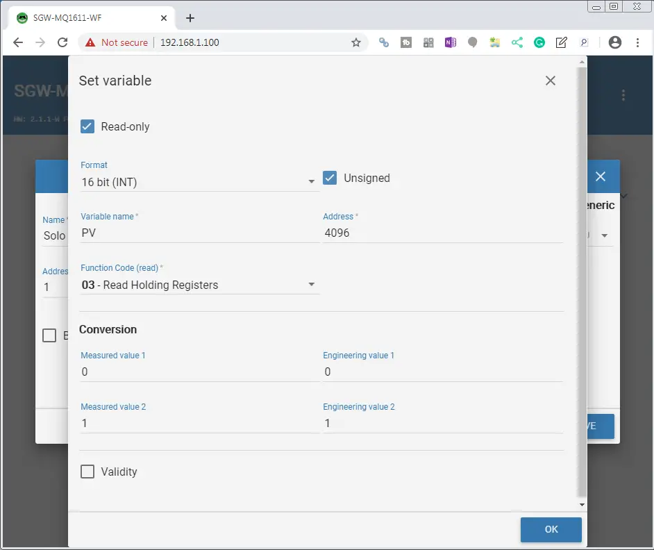
The conversion is used to translate the measured values into engineering values. (Scaling) We will not be using this function. Select OK.

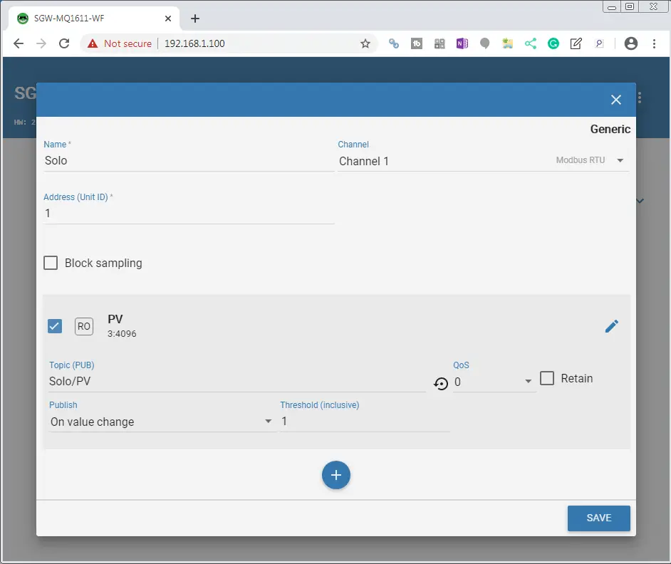
Check the box beside the RO (Read-Only) PV that we have just programmed. This will call up the parameters that we need for this MQTT publishing / subscribing topic.
Our topic(PUB) will be Solo/PV. The quality of service (QoS) will be left at 0. We will publish on a value change and the threshold will be set for 1.
Select the + symbol again to add the set value (SV) of our Solo.
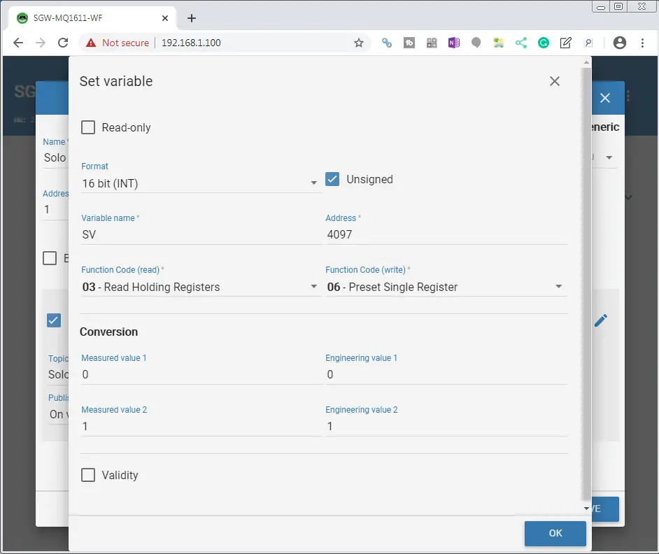
Uncheck the read-only box. The format will be 16-bit (INT) unsigned. Our variable name will be SV and the address will be 4097. (The address is one less than what is in the manual.)
The Modbus function code to read is 03 – Read Holding Registers. Write will use the Modbus function code of 06 – Preset Single Register. Select OK.
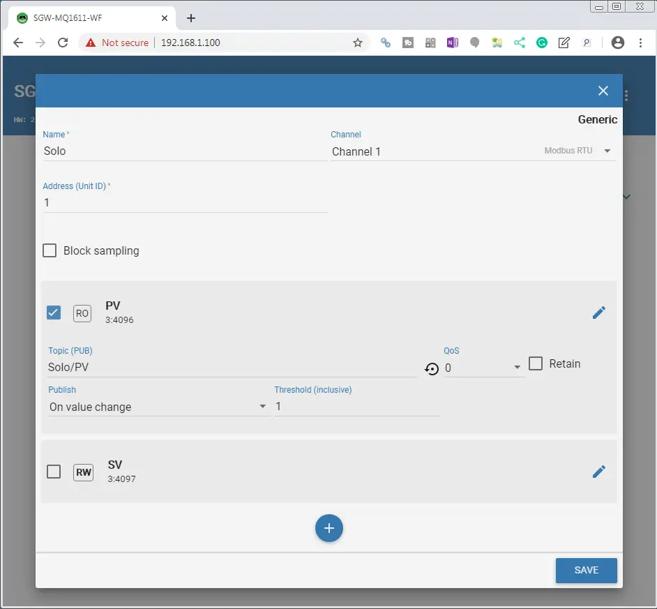
Check the box beside the RW (Read-Write) SV.
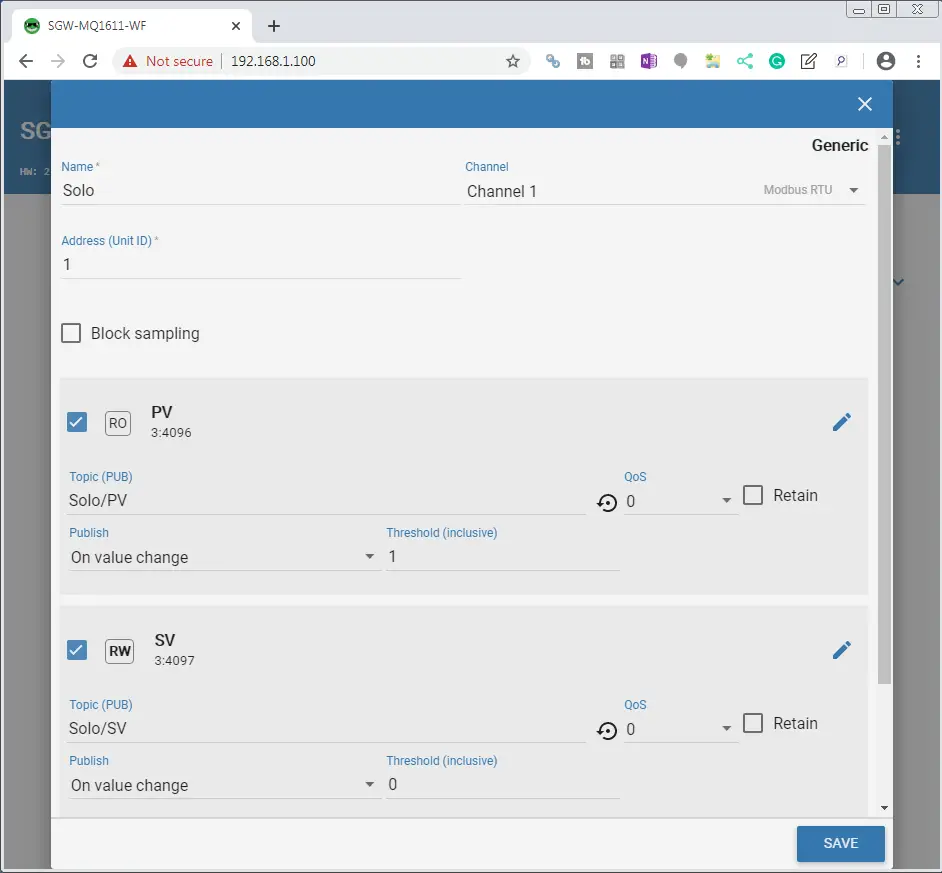
Our topic (PUB) will be Solo/SV and we will publish again on a value change. Select SAVE.
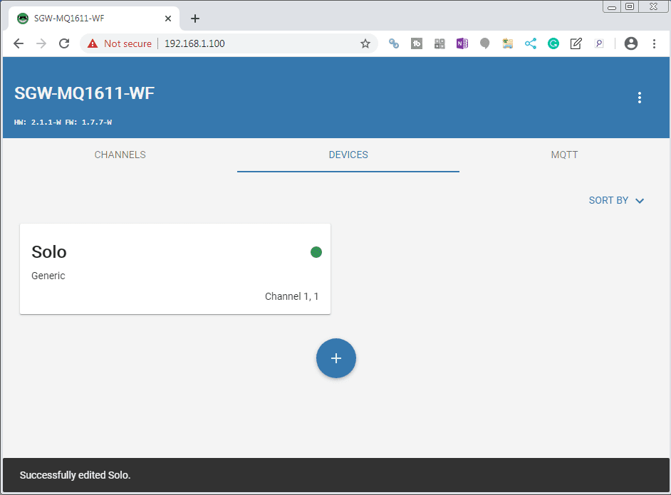
Our Solo device is now programmed. A message will show us that we successfully edited the Solo device. You will notice a green dot on the device to indicate that the communication is good.
MQTT Settings
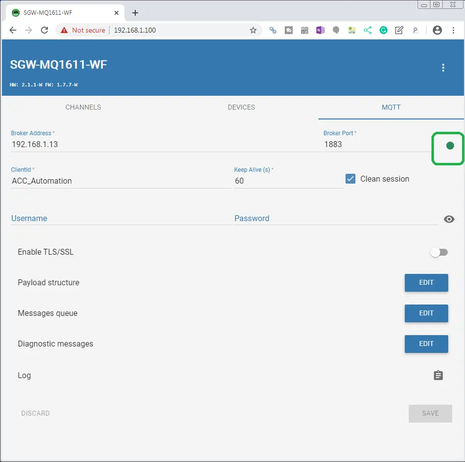
The MQTT settings are used to connect to our broker. Select the MQTT tab.
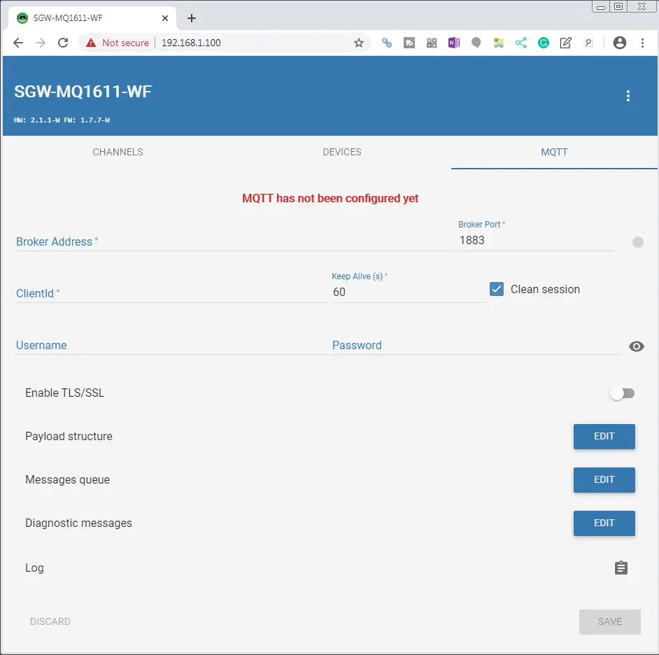
The broker address will be the IP address of our MQTT broker (Mosquitto). Client Id will be set for ACC_Automation. We will leave all the other settings as their defaults. Select SAVE.
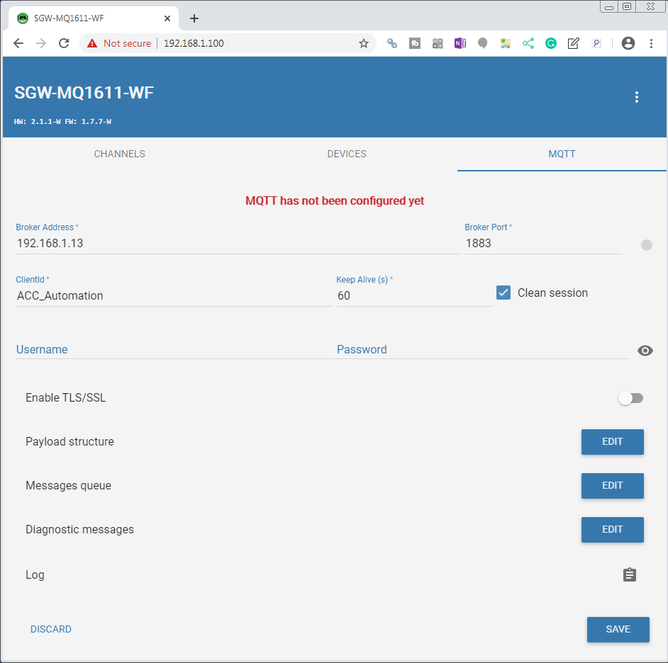
You will notice that we will get a green dot after saving to indicate that the MQTT gateway is now connected and communicating to our MQTT broker.
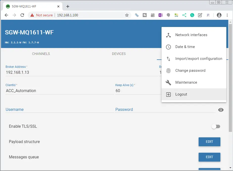
Select the three dots in the upper right corner. Select Logout.
We have now finished programming our Stride MQTT Gateway.
Watch the video below to see the MQTT Gateway communicating to our Mosquitto Broker.
Mosquitto Broker
We will start our Mosquitto broker. The BRX Do-More PLC MQTT Communication post will describe the steps required to download and install this broker.
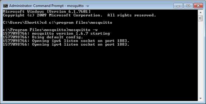
We will start the broker in verbose mode so we can see the communication from our MQTT gateway and MQTTLens client.
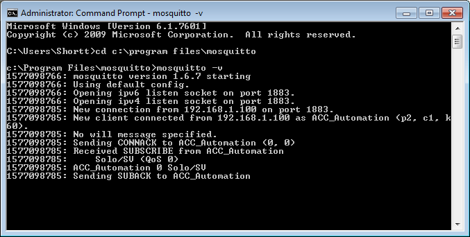
You can see our MQTT gateway establishing communication.
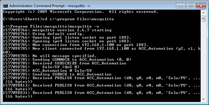
Information is now being published by our gateway.
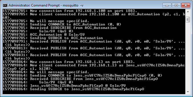
Google MQTTLens has now established communication to the broker.
Google MQTTlens
We will start our MQTTlens client. The BRX Do-More PLC MQTT Communication post will describe the steps required to download and install this client.
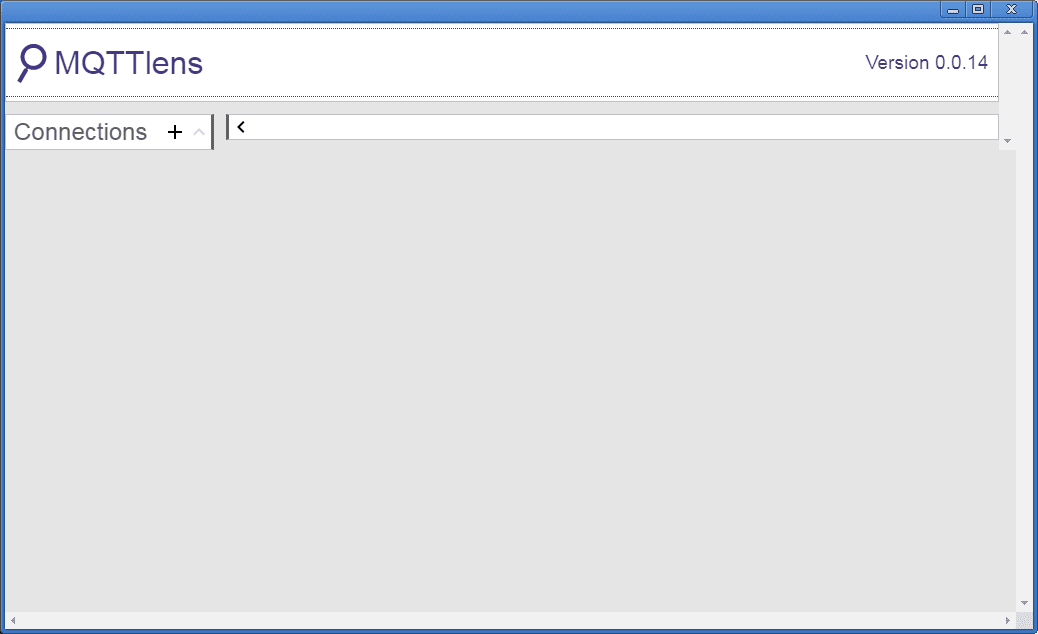
Select Connections +.
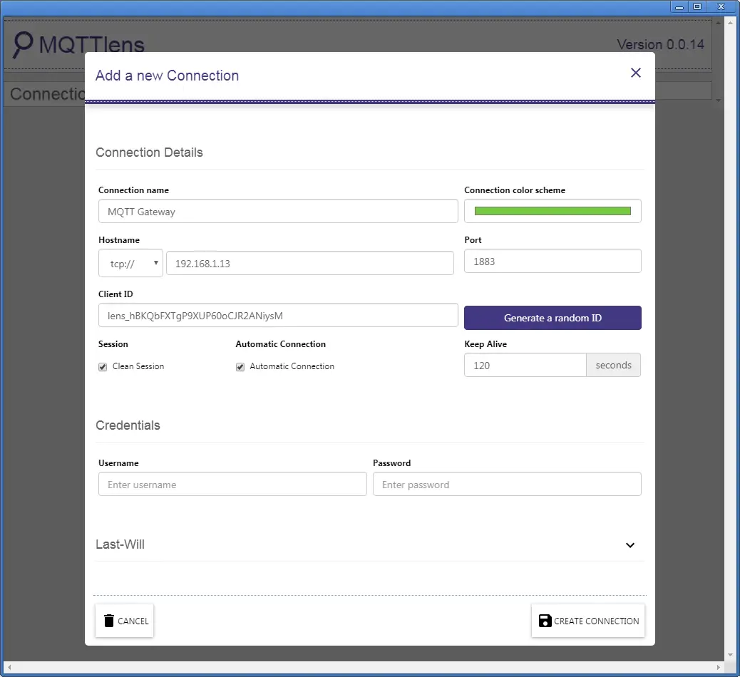
Our connection name will be MQTT Gateway. The hostname will be the IP address of our broker. We will keep all of the other selections as their default. Select Create Connection.
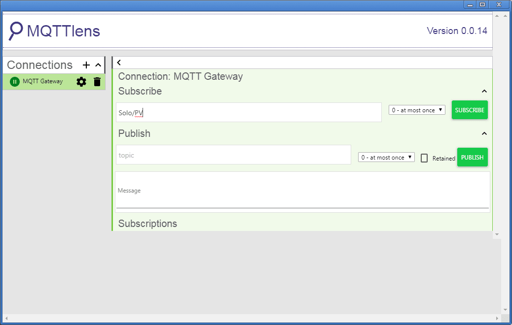
Type Solo/PV under the Subscribe and select SUBSCRIBE.
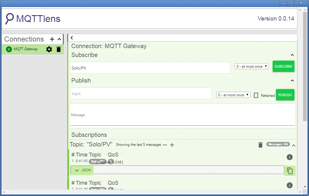
Our present value from the Solo will now be read.
Type Solo/SV under the Publish and enter a value of 300 in the message. Select PUBLISH.
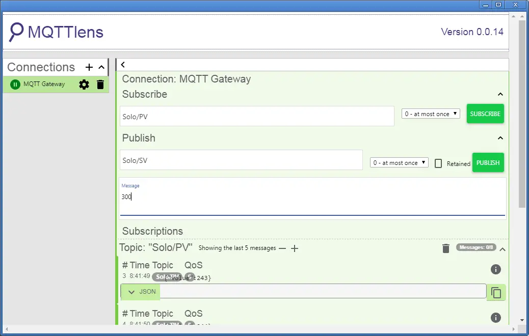
This will put the set value of 30.0 in the Solo process temperature controller.
Watch the video below to see the MQTTlens client controlling our Solo process temperature controller via the Stride MQTT Gateway.
STRIDE MQTT Gateway Features
– Convert Modbus RTU/TCP to MQTT
– IIoT MQTT protocol with SSL/TLS
– Configurable via a web page
– Hardware watchdog function
– Full electrical isolation
– MQTT cloud compatible with AWS, Mosquitto and more
– Wired or Wi-Fi models available
– CE and FCC agency approvals
Stride MQTT Gateway Specifications
Stride MQTT Gateway Manual
Purchase – Stride MQTT Gateway
Stride MQTT Gateway Firmware Update
Next time we will look at connecting the Click PLC to our Stride MQTT Gateway via Modbus TCP.
Watch on YouTube: Stride MQTT Gateway Modbus RTU TCP
If you have any questions or need further information please contact me.
Thank you,
Garry
If you’re like most of my readers, you’re committed to learning about technology. Numbering systems used in PLC’s are not difficult to learn and understand. We will walk through the numbering systems used in PLCs. This includes Bits, Decimal, Hexadecimal, ASCII and Floating Point.
To get this free article, subscribe to my free email newsletter.
Use the information to inform other people how numbering systems work. Sign up now.

The ‘Robust Data Logging for Free’ eBook is also available as a free download. The link is included when you subscribe to ACC Automation.