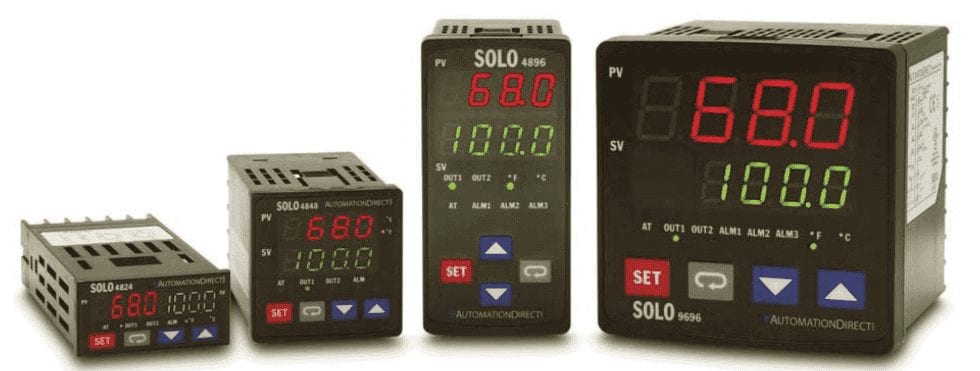
The SOLO Temperature Controller is a single-loop dual-output process temperature controller that can control both heating and cooling simultaneously. It is available in 1/32, 1/16, 1/8, and 1/4 DIN panel sizes and is UL, CUL, and CE-approved.
There are four types of control modes:
PID (Auto Tuning (AT) function) – Solo Control Modes
P stands for proportional and accounts for present values of the error – It reacts to the amount of error which is the difference between the SP (Set Point) and the PV (Present Value)
I stands for integral and accounts for past values of the error – It uses math to basically find the approximation of the area under the curve.
D stands for derivative and accounts for possible future values of the error, based upon the rate of change – It uses math to determine the slope of the error over time and multiply this by the derivative gain.
AT – Auto-Tuning as the name implies will automatically cycle your control system through two cycles and set the PID parameters.
ON / OFF – Solo Control Modes
On/Off control is the simplest form of control. In the case of temperature, the output will be on when the temperature is below-set point. When the temperature gets above the set point of the controller the output will be off. When this cycling occurs frequently, you can add hysteresis to the output. This will limit the time the output goes on and off by a number of degrees.
Manual – Solo Control Modes
Manual mode is when you need to control the output directly. By entering manual mode the operator can adjust the values of the output(s).
Ramp / Soak control – Solo Control Modes
The Ramp / Soak control mode is used to control the outputs according to the pre-programmed SP patterns with the PID control method. The Solo can have eight programs with eight steps each. Note: This can be increased with the additional use of hardware and software via HMI or PLC.
Output Types – Solo Process Temperature Controller
The available outputs include relay, voltage pulse, current, and linear voltage. There are up to three alarm outputs available to allow seventeen alarm types in the initial setting mode. SOLO can accept various types of thermocouple, RTD, or analog input. This means that cascade control is possible with these controllers.
Cascade (Application)
When you use the output of one of the Solo process controllers as the input to another, this would be cascade control.
Modbus RTU and Modbus ASCII Communication
It has a built-in RS-485 interface using Modbus slave (ASCII or RTU) communication protocol.
The Solo Process Temperature Controller can be configured through the buttons on the front of the unit or by the configuration software. Monitoring of up to four controllers at once can be done through the same configuration software.
The following is the wiring of the Modbus Serial communication. We will use a USB to RS485 converter from Automation Direct. (USB-485M)
Installation and operation instructions can be found at the following link: USB to RS485 PC Adapter Installation

Solo Setup
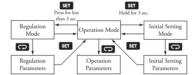
The solo process temperature controller needs to be set up before we can communicate to it. The default setting is ‘Off’ for the On-Line Configuration. Here is the way to change into the different modes in the Solo.
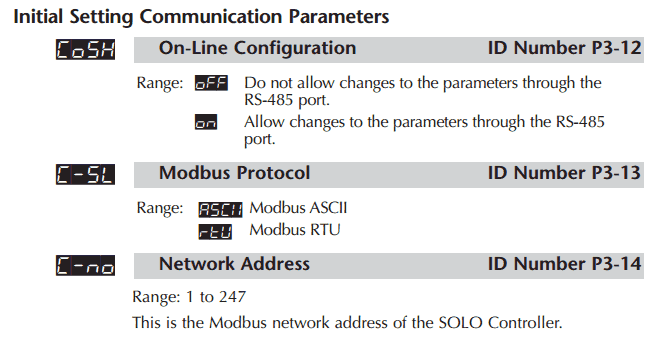
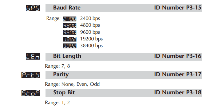
In the Initial Setting Mode we will change the online configuration and make the changes to the Modbus settings as follows: 9600 Baud, Even, 7 Data Bits, 1 Stop Bit, Modbus ASCII Format. We will leave the default unit number as 1.
Our controller is now set to communicate.
Download the documentation and/or configuration and monitoring software at the following URL link:
http://support.automationdirect.com/products/solo.html
The configuration and monitoring software does not have to be installed. You just need to download the file “slsoft.zip”.
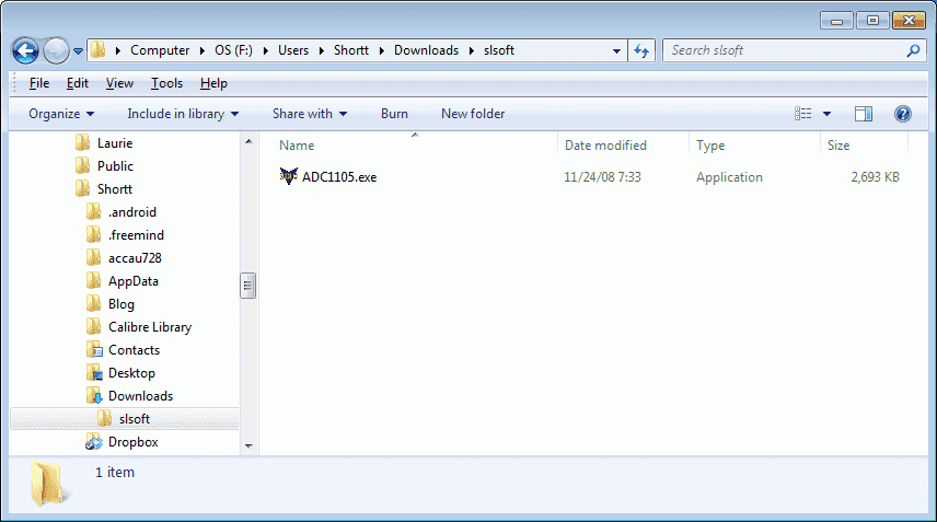
Once downloaded right click on the file and select “Extract All…”. The file ADC1105.exe can now be run.
The recommended screen resolution is 1024 x 768. If you do not have this resolution then there is another program that will allow us to create a shortcut to this program and change our default resolution. After we exit the program, our screen resolution will return to its original state.
Reso is a free application that works well. It can be downloaded at the following URL link:
https://www.majorgeeks.com/files/details/res_o_matic.html
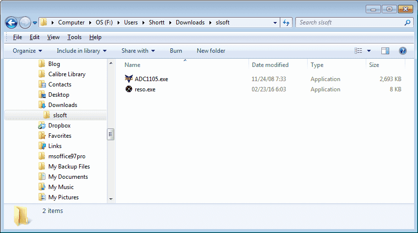
Download the exe file (reso.exe) into the same extracted folder that you have the ADC1105.exe file.
Click on the reso.exe file in the folder to run the application.
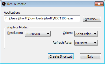
Click the Browse… button and select the ADC1105.exe solo configuration software.
Under the Graphics Mode: Resolution: select 1024×768
We can leave the rest to the defaults as shown below. Now Click Create Shortcut.
Put the shortcut in the same directory as the software that was downloaded.
We will receive notification that the shortcut was created. Click OK.
Our folder will now look like this.
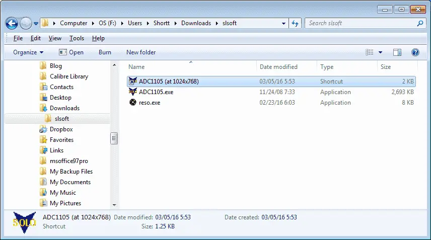
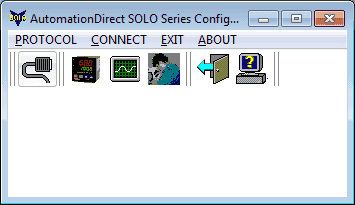
Click on our shortcut (ADC1105 (at 1024×768)) to start the Automation Direct Solo Series Configuration Software.
There are six icons on the main menu. Follow these in order from left to right to set up or troubleshoot your system.
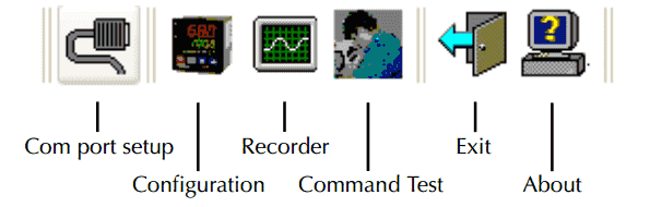
Under the Com port setup, we configure the serial port of the computer to communicate to the Solo. In our case we will use COM5, 9600, Even, 7 Data Bits, 1 Stop Bit, Modbus ASCII Format.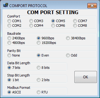
In the Configuration menu, we will select the address of the controller that we will be communicating. This will be the default of the Solo which is 1.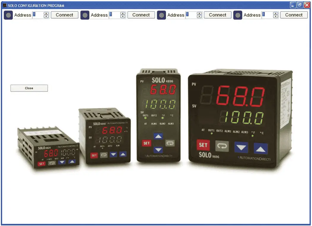
Selecting Connect will then communicate to the Solo process temperature controller and you will see on the screen a picture of the controller with the PV, SV and indicator lights active. 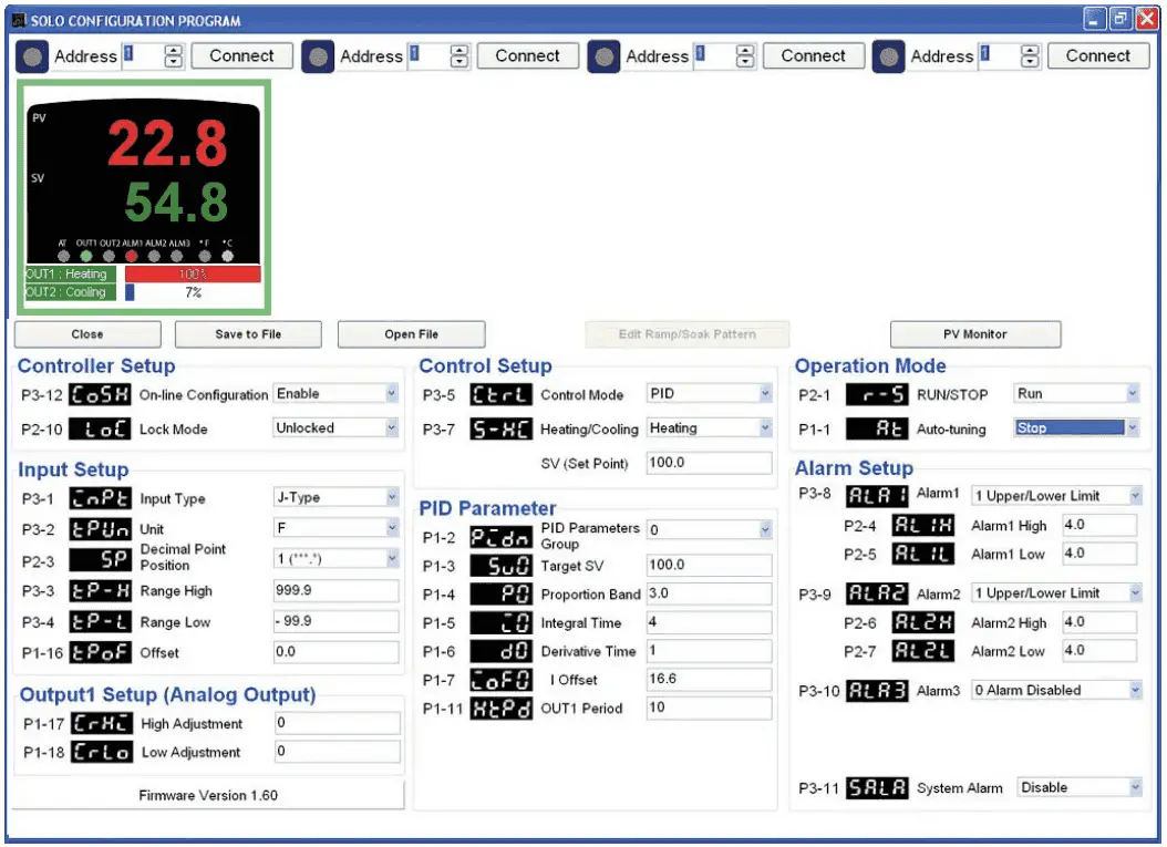
This screen will now allow you to set up all of the parameters in the Solo. Once you enter a value it will be red on the screen. After hitting enter on the keyboard and the value will then be sent to the controller and be displayed in black again.
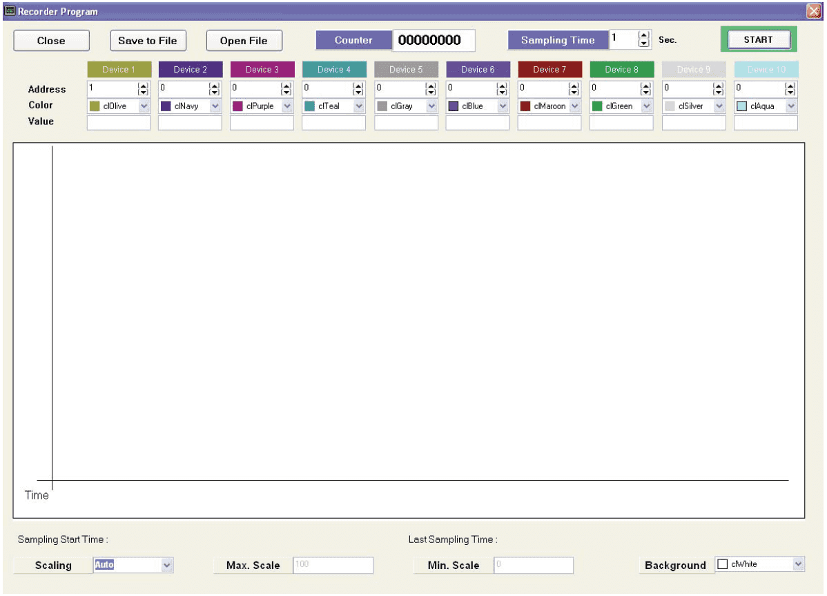
The recorder screen is used to monitor the temperature over time. You can monitor up to ten Solo Controllers at once.
Command Test is used to send individual Modbus command out. This is done in Hexadecimal.
The software for the Solo Process Temperature Controllers is very functional. Using the Reso software, you will be able to put the Solo Software in the 1024 x 768 that it was created for without manually changing the screen every time.
Watch on YouTube: Solo Process Temperature Controller
Watch on YouTube: Analog Input to a Solo Process Temperature Controller
If you have any questions or need further information please contact me.
Thank you,
Garry
If you’re like most of my readers, you’re committed to learning about technology. Numbering systems used in PLC’s are not difficult to learn and understand. We will walk through the numbering systems used in PLCs. This includes Bits, Decimal, Hexadecimal, ASCII and Floating Point.
To get this free article, subscribe to my free email newsletter.
Use the information to inform other people how numbering systems work. Sign up now.

The ‘Robust Data Logging for Free’ eBook is also available as a free download. The link is included when you subscribe to ACC Automation.