We will now look at the secret of using counters in the PLC. (Secret Using Counters) Counters are used in the majority of PLC programs. This is especially true if part of your SCADA system. Counters like the animated picture above count things. In this situation, we count the number of turns the little guy makes. The counter displays the total number. This is considered a totalizing counter. If the output is turned on to do something, it would be a preset (target number entered for the count) counter. There are also a wide variety of off-the-shelf industrial counters that you can use. The implementation of counters can be vast; however, it all starts with a TIMING CHART. This is the same as the timing charts discussed in ‘The Secret of Timers’ post.
Timing Chart – Secret of Using Counters
A timing chart is a secret behind understanding the counter you need in your application. Making a timing chart before writing the program will ensure that all information will be accounted for.
The timing chart is mapped out on an x and y plain. The ‘x’ table will show the time. The ‘y’ plain has the state of the input on/off (1 or 0).
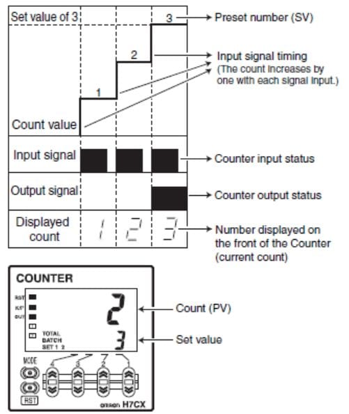
The following shows a timing chart for a counter:
 As you can see in this timing chart, you have an input, output, and display.
Inputs – Secret of Using Counters
Inputs usually use sensors wired to the counter (PLC) to indicate the items we need to count. They can be switches, photoelectric sensors, proximity sensors, encoders, etc. (Wiring of NPN / PNP devices). A counter will generally have only one input. In the case of an encoder input, it is still only one input. However, this is usually wired as A, B, and Z phases. Z is always the reset. A and B indicate the pulses and are leading or trailing each other by 90 degrees, depending on direction. Many counters will also allow you to add a direction input signal. However, this is still only one input.


Outputs – Secret of Using Counters
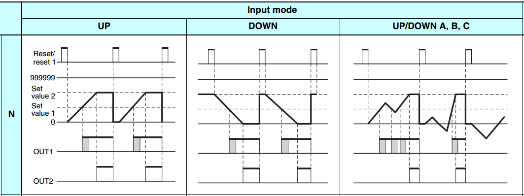
Outputs from counters are generally discrete. This means that they are on or off, similar to the inputs. Outcomes will trigger when the count value matches the set value. The output’s duration depends on the reset signal to start the count again. (DC Solenoids protection) A lot of the counters today will allow you to have multiple outputs. These multifunction counters can have several preset outcomes that trigger when the counter set value has been reached. Batch outputs are also available on some of the industrial counters. A batch output counts the number of times the preset has been reached. This output will be turned on when the number entered for the batch has been reached.
Set Value – SV – Secret of Using Counters
This is usually on display and shows the preset value. It is the target number of counts.
Present Value – PV – Secret of Using Counters
This is usually on display and shows the current or accumulated value.
The PLC programming is usually not that much different than the industrial counter. Many manufacturers will have an up counter, a down counter, and an up/down counter. As the name implies, the display counts up or down. You have to refer to the instruction manual of the manufacturer you are programming for how the counter will be programmed.
The above example Do-More PLC program has an up and a down counter. X0 is the input, and X1 is the reset on both counters. (CT0, CT1)
The preset value is stored in memory location D0. This value is set to the number 3.
When the present value (accumulated) reaches the set value (preset), then the CT0. A done bit goes on, and the output Y0 is active. Y0 will remain on until the reset input goes on.
The only difference for the down counter is the display. You will see that the present value will count down to zero (0) before the CT1. A done bit is turned on.
These counters are memory retentive. So to make the counter non-memory retentive, use the first scan bit of the PLC to trigger the counter reset. (ST0 – $FirstScan)
Every PLC has counters. They all have different types depending on what you are trying to achieve. It will all start with your Timing Chart.
Watch on YouTube: Learn PLC Programming – Free 9 – The Secret of Counters
If you have any questions or need further information, please get in touch with me.
Thank you,
Garry
If you’re like most of my readers, you’re committed to learning about technology. Numbering systems used in PLCs are not challenging to learn and understand. We will walk through the numbering systems used in PLCs. This includes Bits, Decimals, Hexadecimal, ASCII, and Floating Points.
To get this free article, subscribe to my free email newsletter.
Use the information to inform other people how numbering systems work. Sign up now.
The ‘Robust Data Logging for Free’ eBook is also available as a free download. The link is included when you subscribe to ACC Automation.


