Programmable Logic Controllers (PLC) will scan very quickly. This can be anywhere from 1 to 20 ms, translating into 1000 to 500 times each second. But what exactly is a scan?
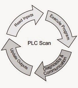
A scan is when the PLC will complete the following:
Read Inputs:
Look at all of the inputs to the programmable controller. Digital, Analog, Communication
Execute Program:
Solve the logic to determine the output status. PLCs generally will solve the logic from left to right, top to bottom. The output of the rung before is available for the next rung.
This is like some of the popular brands of PLCs like
Mitsubishi,
Allen Bradley,
Siemens,
Omron,
Automation Direct, etc. Some exceptions, like older Modicon models, solve the logic top to bottom, left to right. Always refer to the manufactures manual to ensure the program execution method.
Diagnostics and Communication:
The PLC will do a self-check. It will verify that no errors exist in memory, cards attached, etc. This is critical because the PLC in an industrial application can have devastating effects if something malfunctions and the machine continues to function erratically. The PLC will stop executing, return the outputs to a normal state, and indicate an error has occurred.
Communication will happen to the remote I/O, operator panels, etc.
Update Outputs:
Outputs are set according to the PLC program. (Digital, Analog) This is where the physical items will start moving. (Motors, Valves, etc.)
To understand the scan, let’s take a look at an example.
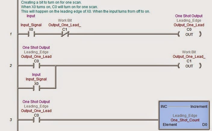
The following program will look at input X0 and set an internal bit for one scan on the rising edge of the input and one on the trailing edge of the input. The rising edge is when the input transitions from off to on, and the trailing edge is when the input transitions from on to off.
The bits will only be on for one scan, so we will increment an internal word by one when the bits go on. This way, we can see the bit increment in the word.
Leading-edge one shot (one scan) bit. When the input signal goes on (X0) and C1 is not on, then C0 is turned on. The next rung will have C0 and X0 on, so C1 turns on.
Remember: The PLC will scan from left to right, top to bottom, and the outputs from the previous rung are available for the next.
C0 is on so that the increment will add one to D0.
In the following scan, X0 is still on, and C1 is now on, so output C0 is turned off. C0 has been on for one scan from the transition from off to on.
Trailing edge one shot (one scan) bit. When the input signal goes off (X0) and C3 is not on, then C2 is turned on. The next rung will have C2, not X0, so C3 turns on.
C2 is on so that the increment will add one to D1.
In the following scan, X0 is still off, and C3 is now on, so output C2 is turned off. C2 has been now on for one scan from the transition from on to off.
Contact me for the above program. I will be happy to email it to you.
If you have any questions or need further information, please get in touch with me.
Thank you,
Garry
You can download the software and simulator for free at the following address. Also listed are helpful guides to walk you through your first program.
Do-more Designer Software
How to use videos for Do-more Designer Software
If you’re like most of my readers, you’re committed to learning about technology. Numbering systems used in PLCs are not challenging to learn and understand. We will walk through the numbering systems used in PLCs. This includes Bits, Decimals, Hexadecimal, ASCII, and Floating Points.
To get this free article, subscribe to my free email newsletter.
Use the information to inform other people how numbering systems work. Sign up now.

The ‘Robust Data Logging for Free’ eBook is also available as a free download. The link is included when you subscribe to ACC Automation.