
The CTT series from Automation Direct are multi-function digital units. They incorporate a multi-function digital counter, timer and tachometer all within the same unit. The counter timer mixed mode will operate in sixteen (16) different ways. Two different count input modes can be selected. Up or Down can be selected. We will program eight of the modes with the UP input. A number of output modes can be selected so this unit can adapt to a great number of applications.
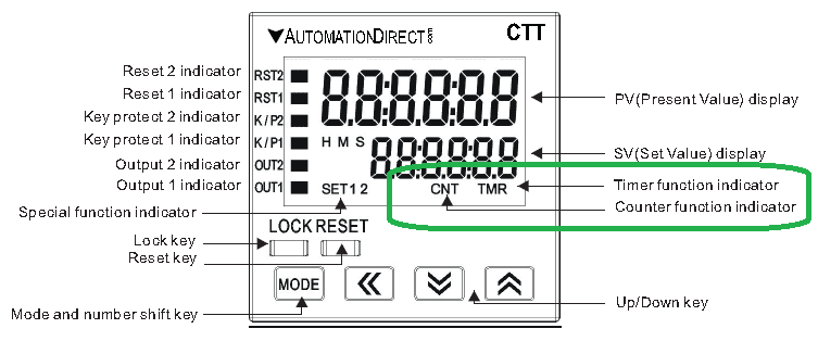
In Timer Counter Mixed Mode, timer period setting value SV1 controls Output 1 and counter setting value SV2 controls Output 2. Let’s get started.
Previously in this CTT Series – Counter / Timer / Tachometer we have discussed;
– CTT Counter Timer Tachometer – Getting Started
o Un-boxing the CTT Video
o Powering up the Unit Video
– CTT Timer Modes
o Signal On Delay 1 Timer
o Signal On Delay 2 Timer
o Signal Off Delay Timer
o Signal On Timer
o Power On Delay Timer
o Power On Delay Hold Timer
o Repeat Cycle Timer
o Repeat Cycle Hold Timer
o Repeat Cycle 2 Timer
o Signal Cumulate Timer
o Signal Twin On Start Timer
o Signal Twin Off Start Timer
– CTT Counter Modes
o Stage 1 Counting
o Stage 2 Counting
o Batch Counting
o Total Counting
o Dual Counting
All timer and counter applications begin with a timing chart. The secret of using timers and counters is a good place to start for a review of how timing charts work.
Programming these units can look like a hard task. The manual is over 260 pages! However, there is an easy way. The manual is broken up into chapters for each of the operation modes of the CTT. (Counter, Timer, Timer + Counter, Tachometer)
Once we find our operation mode, you look for the timing chart mode for your application. The manual includes all of the information that you need for that mode. This includes wiring diagrams, timing charts, program steps, and dip switch settings.
Example – CTT Signal on Delay 1 Counting Up timer counter mixed-mode – Page 4-3 and 4-7 contain all of the information needed to program this mode.
Counter Input Mode – Counting Up (UP)
Each leading edge of the input signal at CP1 will increment the count present value PV by 1. All of our sample programs will use the counting up input mode.
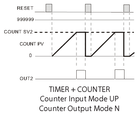
CTT Timer + Counter Mixed Mode Functions
In Timer + Counter Mixed Mode, timer period setting value SV1 controls Output 1 and counter setting value SV2 controls Output 2. Output 1(Timer) will turn ON momentarily for the time set in the output pulse width parameter (tout1) or will be maintained ON (tout1 set to 0.00). Output 2 (Counter) will turn ON momentarily for the time set in the output pulse width parameter (tout2) or will be maintained ON depending on the output mode selected.
Signal On Delay 1 Up – Counter Timer Mixed Modes
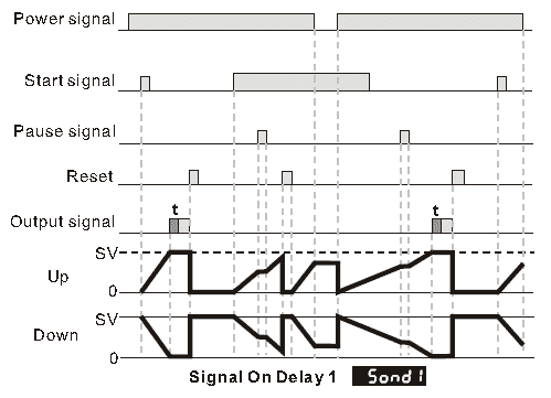
With power applied to the CTT, the leading edge of an input signal at START will begin the timing period setting value SV1 timing up or down based on parameter
(t modE). At the end of the timing period Output 1 will turn ON momentarily for the time set in the output pulse width parameter (tout1) or will be maintained ON if the output pulse width parameter (tout1) is set to 0.00. The trailing edge of the “start” signal has no effect on the outputs or timing period.
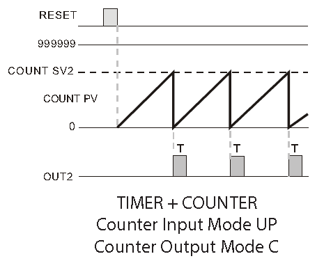
When the count present value PV counts up to the count setting value SV2 Output 2 will turn ON. The count PV will remain at the count SV2 regardless of additional input signals.
Watch on YouTube : CTT Signal On Delay 1 Up
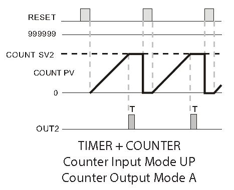
Signal On Delay 2 Up – Counter Timer Mixed Modes
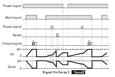
With power applied to the CTT, the leading edge of an input signal at START will begin the timing period setting value SV1 timing up or down based on parameter (t modE). At the end of the timing period Output 1 will turn ON momentarily for the time set in the output pulse width parameter (tout1) or will be maintained ON if the output pulse width parameter (tout1) is set to 0.00. The trailing edge of the “start” signal will turn OFF Output 1 and reset the timing period.
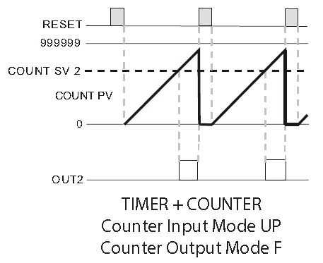
When the count present value PV counts up to the count setting value SV2 Output 2 will turn ON momentarily for the time set in the output pulse width parameter (tout2) and the count PV will reset automatically to 0.
Watch on YouTube : CTT Signal On Delay 2 Up
Signal Off Delay Up – Counter Timer Mixed Modes
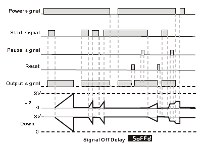
With power applied to the CTT, the leading edge of an input signal at START will immediately turn ON the Output 1. The trailing edge of the “start” signal will begin the timing period setting value SV1 timing up or down based on parameter (t modE). At the end of the timing period Output 1 will turn OFF. The leading edge of a “start” signal applied during a previously initiated timing period will reset the timing period.
When the count present value PV counts up to the count setting value SV2 Output 2 will turn ON. The count PV will continue to increment with each input signal.
Watch on YouTube : CTT Signal Off Delay Up
Signal On Up – Counter Timer Mixed Modes
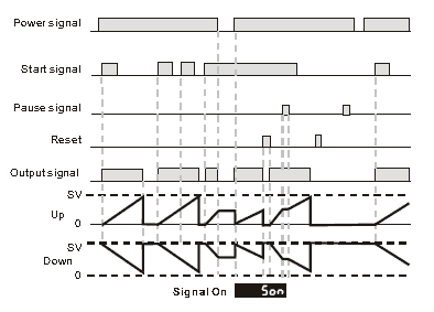
With power applied to the CTT, the leading edge of an input signal at START will immediately turn ON Output 1 and begin the timing period setting value SV1 timing up or down based on parameter (t modE). The trailing edge of the “start” signal has no effect on the output or timing period. At the end of the timing period Output 1 will turn OFF and the timing period will reset. The leading edge of a “start” signal applied during a previously initiated timing period will not reset the timing period.
When the count present value PV counts up to the count setting value SV2 Output 2 will turn ON momentarily for the time set in the output pulse width parameter (tout2).
The count PV is prohibited from incrementing until the end of the output pulse time (tout2) when the Output 2 turns OFF and the count PV is reset automatically to 0.
Watch on YouTube : CTT Signal On Up
Power On Delay Up – Counter Timer Mixed Modes
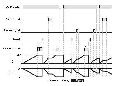
When power is applied to the CTT, the timing period setting value SV1 will begin timing up or down based on parameter (t modE). At the end of the timing period Output 1 will turn ON momentarily for the time set in the output pulse width parameter (tout1) or will be maintained ON if the output pulse width parameter (tout1) is set to 0.00.
When the count present value PV counts up to the count setting value SV2 Output 2 will turn ON momentarily for the time set in the output pulse width parameter (tout2). The count PV will continue to increment with each input signal.
Watch on YouTube : CTT Power On Delay Up
Power On Delay Hold Up – Counter Timer Mixed Modes
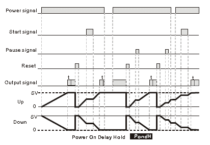
When power is applied to the CTT, the timing period setting value SV1 will begin timing up or down based on parameter (t modE). At the end of the timing period Output 1 will turn ON momentarily for the time set in the output pulse width parameter (tout1) or will be maintained ON if the output pulse width parameter (tout1) is set to 0.00.
When the count present value PV counts up to the count setting value SV2 both Output 2 will turn ON momentarily for the time set in the output pulse width parameter (tout2). The count PV display is prohibited from incrementing until the end of the output pulse time when Output 2 turns OFF and the count PV is reset automatically to 0 and any input signals that occurred during the output pulse time.
Watch on YouTube : CTT Power On Delay Hold Up
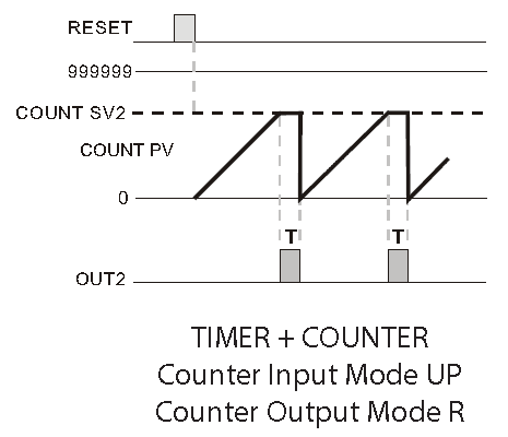
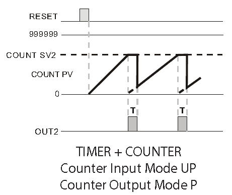
Repeat Cycle Up – Counter Timer Mixed Modes
With power applied to the CTT, the leading edge of an input signal at START will begin the timing period setting value SV1 timing up or down based on parameter (t modE). At the end of the timing period, the timing period will reset and repeat automatically.
If the output pulse width parameter (tout1) is set to 0.00 Output 1 will turn ON at the end of the first timing period, turn OFF at the end of the next timing period, turn ON at the end of the next timing period, etc.
When the count present value PV counts up to the count setting value SV2 Output 2 will turn ON momentarily for the time set in the output pulse width parameter (tout2). The count PV will continue to increment with each input signal until the end of the output pulse time when Output 2 turns OFF and the count PV is reset automatically to 0.
Watch on YouTube : CTT Repeat Cycle Up
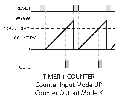
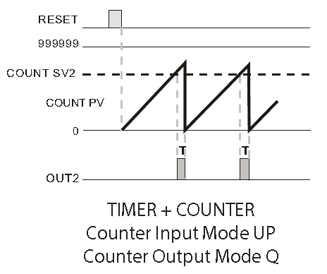
Repeat Cycle Hold Up – Counter Timer Mixed Modes
With power applied to the CTT, the leading edge of an input signal at START will begin the timing period setting value SV1 timing up or down based on parameter (t modE). At the end of the timing period, the timing period will reset and repeat automatically.
If the output pulse width parameter (tout1) is set to 0.00, Output 1 will turn ON at the end of the first timing period, turn OFF at the end of the next timing period, turn ON at the end of the next timing period, etc.
If the output pulse width parameter (tout1) is set to >0.00, Output 1 will turn ON momentarily for the time set in the output pulse width parameter (tout1) at the beginning of the each timing period.
When the count present value PV counts up to the count setting value SV2 both Output 2 will turn ON momentarily for the time set in the output pulse width parameter (tout2). The count PV will remain at the count SV2 regardless of additional input signals.
Watch on YouTube: CTT Repeat Cycle Hold Up
CTT Counter Timer Tachometer – Summary of features
– Can operate as a digital counter, timer, combination timer + counter, or tachometer
– Accepts voltage and non-voltage inputs from a wide variety of NPN, PNP, or dry contact sensors
– Selectable counting speeds from 1 to 10,000 cycles per second
– Multiple transistors and relay outputs can operate as momentary or maintained
– Double-line, 6-digit, 2-color LCD display
– Easy configuration with externally accessible DIP switches or the lockable keypad
– Display decimal point selection
– Available in 100-240VAC and 24VDC powered models
– UL508 listed (E311366), cULus, CE marked
Counter, Timer, Tachometer – CTT Series from Automation Direct
Shop Multi-Function Digital Counter / Timer / Tachometer
CTT Overview
https://cdn.automationdirect.com/static/specs/cttcountertimertachoverview.pdf
CTT Quick Start Guide
https://cdn.automationdirect.com/static/manuals/cttqsg/cttseries_qsg.pdf
Digital CTT Manual
https://cdn.automationdirect.com/static/manuals/digitalctt/digitalctt.html
Rhino Power Supply
https://www.automationdirect.com/adc/Overview/Catalog/Power_Products_(Electrical)/DC_Power_Supplies
https://cdn.automationdirect.com/static/specs/pslpowersupplies.pdf
Next time we will look at the programming of the tachometer mode in the CTT.
If you have any questions or need further information please contact me.
Thank you,
Garry
If you’re like most of my readers, you’re committed to learning about technology. Numbering systems used in PLC’s are not difficult to learn and understand. We will walk through the numbering systems used in PLCs. This includes Bits, Decimal, Hexadecimal, ASCII and Floating Point.
To get this free article, subscribe to my free email newsletter.
Use the information to inform other people how numbering systems work. Sign up now.

The ‘Robust Data Logging for Free’ eBook is also available as a free download. The link is included when you subscribe to ACC Automation.