
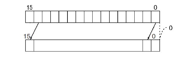
Shift registers will move (shift) bits in a word (register) to the left or right.
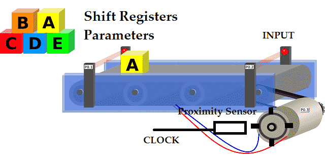
If we look at an example of boxes moving along a conveyor belt, the boxes would represent the bits in the register. The movement of the conveyor would be the shifting of the register that represents the movement of the boxes.

Shift registers are a form of sequential logic, which involves the present inputs and the prior history. All of the prior history is remembered.
We will be making a shift register in PLC Fiddle with the instructions provided. The output of the shift register will then be looked at for a reject area. Let’s get started.
Previously we discussed the free virtual PLC simulator called PLC Fiddle and created some challenges. These challenges are ladder logic that you can solve in your browser.
PLC Fiddle Online Editor and Simulator in your Browser – Video
Basic Gate Ladder Logic Challenges
– AND Gate Ladder Logic Challenge Solution
– OR Gate Ladder Logic Challenge Solution
– NAND Gate Ladder Logic Challenge Solution
– NOR Gate Ladder Logic Challenge Solution
– EXOR Gate Ladder Logic Challenge Solution
– EXNOR Gate Ladder Logic Challenge Solution
Timer Challenge
– On-Delay Timer Challenge Solution
– Off-Delay Timer Challenge Solution
– Pulse Output Timer Challenge Solution
Counter Challenge
– Motor Starter Service Counter Challenge Solution
– Count Down Challenge Solution
– Hour Minute Second Counter Challenge Solution
PLC Fiddle Math Challenge
– Occupancy Count Challenge Solution
– Degree F and C Challenge Solution
– Determine the Scan Rate of PLC Fiddle Challenge Solution
Compare Challenge
– Motor Starter Service Stop Challenge Solution
– Flasher Challenge Solution
– Simple Traffic Light Challenge Solution
Our challenges will be to create a 16-bit shift register and then use an output bit of the shift register. We will first learn exactly what a shift register is and look at some sample PLC applications and code.
Shift Register Description – What it is?
Shift registers usually have three inputs to the instruction.
Input – This is the information shifted into the register or word. It is either a one (1) or zero (0).
Clock – The clock is used as a trigger to shift the bits. In the case of a conveyor belt, the clock would be the movement of the belt by use of time, encoder or sensor (proximity) off of a sprocket. Every pulse of the clock would represent a certain amount of movement on the conveyor.
Reset – This input will reset the shift register. Place zeros into the register or word.
We have done prior examples with shift registers. Here are a few links to help you understand the function and use of the shift register.
PLC Programming Example Sift Register Conveyor Reject – Video
PLC Programming Example Sorting Station Shift Register – Demonstration Video – Explanation Video
Horner XL4 Rotate and Shit Register – Video
Click PLC Shift Register Instruction – Video
BRX PLC Shifting Instructions – Video
Omron CP1H Data Shifting Instructions – Video Part 1 – Video Part 2
Productivity 1000 Series PLC Data Handling Instructions Part 2 – Video
Bit Shifting Math
Bits shift from the least significant bit (LSB) 00 to the most significant bit (MSB) 15 when they shift to the left. The value in the register doubles when this shift happens. (X2) When the bits shift from the MSB to the LSB they shift to the right. This will half the value of the register. (/2) We can see this in the following chart that will display the value of a 16 bit register (word).
| (MSB) – Binary Value – (LSB) | Decimal Value (Binary Coded Decimal – BCD) |
| 0000 0000 0000 0000 | 0 |
| 0000 0000 0000 0001 | 1 |
| 0000 0000 0000 0010 | 2 |
| 0000 0000 0000 0100 | 4 |
| 0000 0000 0000 1000 | 8 |
| 0000 0000 0001 0000 | 16 |
| 0000 0000 0010 0000 | 32 |
| 0000 0000 0100 0000 | 64 |
| 0000 0000 1000 0000 | 128 |
| 0000 0001 0000 0000 | 256 |
| 0000 0010 0000 0000 | 512 |
| 0000 0100 0000 0000 | 1024 |
| 0000 1000 0000 0000 | 2048 |
| 0001 0000 0000 0000 | 4096 |
| 0010 0000 0000 0000 | 8192 |
| 0100 0000 0000 0000 | 16384 |
| 1000 0000 0000 0000 | 32768 |
You can see from the chart above as you shift the bit to the left you will double the value of the register. Shifting to the right will divide the register by 2.
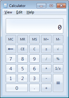
You can try this yourself with the window calculator.
To display the programmer calculator select from the main menu | View | Programmer.
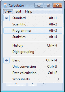
Alternatively, you can use the short cut keys of ALT + 3 to change to the programmer calculator.
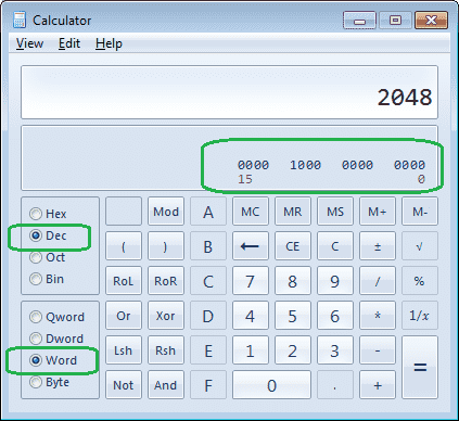
The decimal value that you enter into the calculator will also display the 16 bits in the word that represents that decimal number. In our example, the value of 2048 decimal has bit 12 on (1) and the rest are off (0).
PLC Fiddle Shift Register Challenge
Create a 16-bit shift register. The clock rate will be done with a self-resetting timer set for 1 second. When the start input is on the shift register will shift the bits left each pulse of the clock rate. If the input is on and the clock pulse is on the first bit (00) will be turned on in the shift register.
Bits shifted past the last bit (15) will be removed.
The reset input will reset the shift register to zero. (0000 0000 0000 0000)
https://www.plcfiddle.com/challenge/369ecd48-3d46-4ce3-8bdf-897201bab4ea
Watch on YouTube: PLC Fiddle Shift Register Challenge Solution
PLC Fiddle Shift Register Output Challenge
Take the existing shift register that we have made in PLC Fiddle and add an output. When bit 12 of the shift register turns on (1) then Bit 12 Output will turn on.
Note: We want to still have all 16 bits of our shift register available.
https://www.plcfiddle.com/challenge/68091ce1-59cd-4686-8f4b-9aa0a047618e
Watch on YouTube: PLC Fiddle Shift Register Output Challenge Solution
The PLC Fiddle shift register challenges have demonstrated the basic coding behind this instruction. Shift registers are common instructions in most PLCs. They will have a variety of different types of shifting instructions. I hope you found the above shift register challenges fun to solve using PLC Fiddle. It demonstrates the basic principles of programming without the investment in equipment.
If you have any questions or need further information please contact me.
Thank you,
Garry
If you’re like most of my readers, you’re committed to learning about technology. Numbering systems used in PLC’s are not difficult to learn and understand. We will walk through the numbering systems used in PLCs. This includes Bits, Decimal, Hexadecimal, ASCII and Floating Point.
To get this free article, subscribe to my free email newsletter.
Use the information to inform other people how numbering systems work. Sign up now.

The ‘Robust Data Logging for Free’ eBook is also available as a free download. The link is included when you subscribe to ACC Automation.