The Horner APG XL4 all in one controller has several different instructions to shift and rotate the bits, bytes, words or double words in the memory. We will be discussing the bitwise operations of the shift and rotate instructions. Looking further into the move operations we will look at the Element Rotate and Element Shift instructions as they pertain to a conveyor belt tracking application.
Previously we discussed the following in our Horner XL4 Series:
System Hardware
Installing the Software Cscape
Cscape Software Setup
Establishing Communication
Numbering System and Addressing
User Interface
Timers and Counters
Compare and Move Instructions
Math Instructions
Program Control Instructions
A review of the shift register can be seen at the following link.
https://accautomation.ca/plc-programming-example-shift-register-conveyor-reject/
YouTube Video: https://www.youtube.com/watch?v=K1j6HvNF-5s
Horner XL4 Rotate and Shift Register instructions
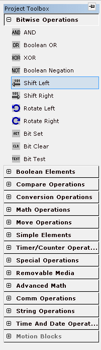
Bitwise Operations
Shift and Rotate elements in the bitwise operation work on either 16 or 32-bit unsigned values.
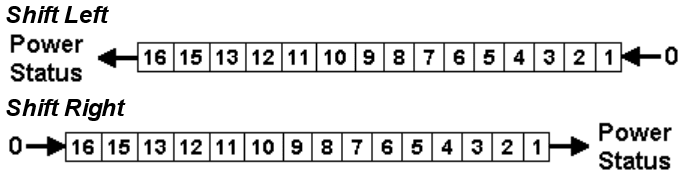
Shifting involves moving the bits in the registers either left or right by a certain number. The trigger to make this happen is by the power flow to the instruction itself. In most cases, we will have to create a positive or negative transition coil in the logic as an input to the instruction. Information that is shifted past the last bit in either direction is lost.
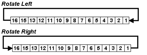
Rotating is also moving the bits in the registers either left or right by a certain number. Information is not lost because the end bits rotate around to the other end as they are moved. This can happen in either direction. The trigger to make this happen is by the power flow to the instruction itself. In most cases, we will have to create a positive or negative transition coil in the logic as an input to the instruction.
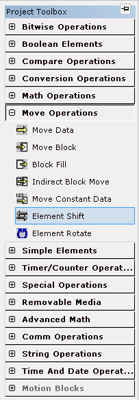
Move Operations – Horner Rotate and Shift Register
Under the move operations, we also have the element rotate and element shift instructions. Let’s now review these two instructions in-depth and operate both.
Element Rotate
This instruction will allow an array of memory to be rotated left or right a variable number of times.
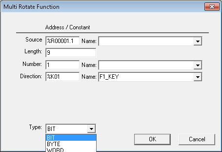
Power Flow – This will trigger the instruction to rotate. Note: This will happen every scan of the PLC so you must use transition coils. See the example below.
Source – This is the starting memory of the rotate. If you are using bits it must specify a bit location. If it is a word then a word location must be specified. Etc.
Length – This is the length of the memory. It is based upon the Type specified. In our example, the length is 9 bits long.
Number – This is the number of rotations to do when the instruction has power flow. In our case, this will be shifted by one.
Direction – This is the direction of the rotation. Right or Left is determined by the status of a bit in memory. We will be using our F1 key as the direction input.
Type – This is the type of rotation that we will be executing. This means that we can rotate by bit, byte, word, or doubleword.
Here is our PLC ladder logic diagram example.
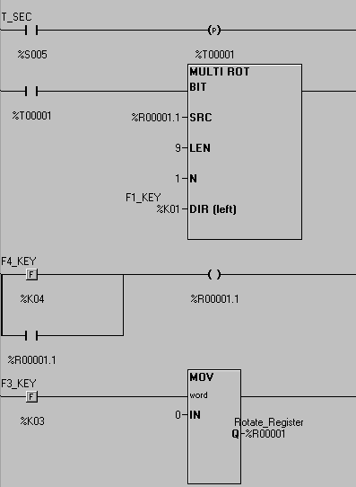
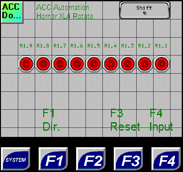
This is our Horner APG HMI screen for the rotate instruction.
See this logic in action by watching the YouTube video below.
Element Shift
This instruction will allow an array of memory to be shifted left or right a variable number of times.
Power Flow – This will trigger the instruction to shift. Note: This will happen every scan of the PLC so you must use transition coils. See the example below.
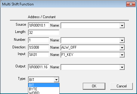
Source – This is the starting memory of the shift. If you are using bits it must specify a bit location. If it is a word then a word location must be specified. Etc.
Length – This is the length of the memory. It is based upon the Type specified. In our example, the length is 32 bits long.
Number – This is the number of rotations to do when the instruction has power flow. In our case, this will be shifted by one bit.
Direction – This is the direction of the rotation. Right or Left is determined by the status of a bit in memory.
Input – This specifies where the input will come from and be placed in our shift register. In our case, this will be the F1 key on the display. The bit status will be shifted into the source location when the instruction is executed (power flow).
Output – This is the last bit of memory that is shifted out of the array.
Type – This is the type of rotation that we will be executing. This means that we can rotate by bit, byte, word, or doubleword.
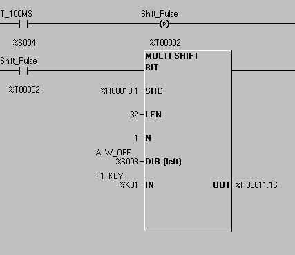
Here is our PLC ladder logic diagram example.
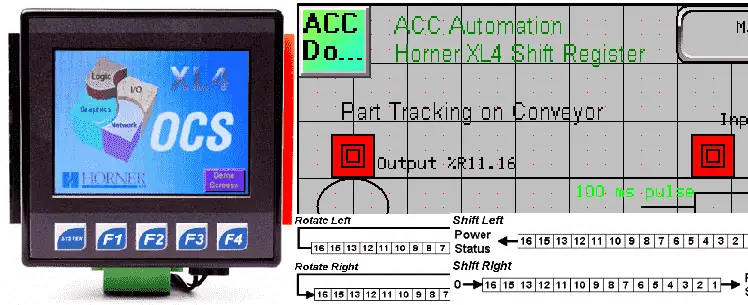
This is our Horner APG HMI screen for the shift instruction. What we are doing is modeling a conveyor belt that is running. (100ms pulse bits) When a product is sensed on the conveyor belt, the F1 key, bits are turned on. These bits represent the product along the conveyor belt. They will turn on an output when they reach a location on the conveyor.
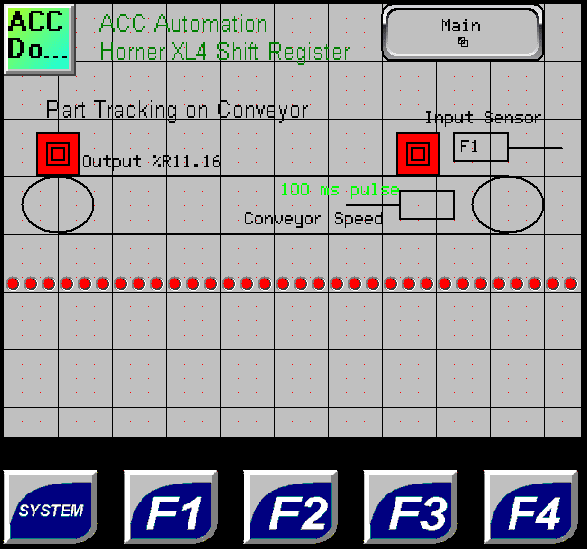
Note: This logic is used for product tracking, reject tracking, etc.
See this logic in action by watching the YouTube video below.
You can download this application here. It will contain all of the screens and logic programming.
All of the documentation for the XL4 can be downloaded at the following URL:
https://hornerautomation.eu/product/xl4-prime-ocs-3-5-colour-touchscreen/
Next time we will look at the recipe instruction.
Watch on YouTube : Horner XL4 Rotate and Shift Register
If you have any questions or need further information please contact me.
Thank you,
Garry
If you’re like most of my readers, you’re committed to learning about technology. Numbering systems used in PLC’s are not difficult to learn and understand. We will walk through the numbering systems used in PLCs. This includes Bits, Decimal, Hexadecimal, ASCII and Floating Point.
To get this free article, subscribe to my free email newsletter.
Use the information to inform other people how numbering systems work. Sign up now.

The ‘Robust Data Logging for Free’ eBook is also available as a free download. The link is included when you subscribe to ACC Automation.