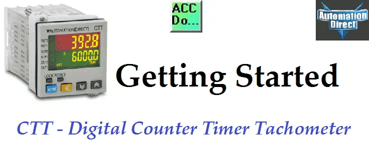
Digital Counter / Timer / Tachometer (CTT Series)
The CTT series from Automation Direct are multi-function digital units. They incorporate a multi-function digital counter, timer and tachometer all within the same unit. This means that you have fewer stock items and the learning curve is minimized. The CCT series are easily configured as a digital counter, timer, combination timer-counter or tachometer.
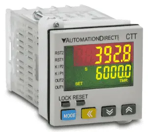
The two colour LCD display shows present values, setting values and menu parameters during setup. Process control parameters are easily set using the externally accessible DIP switches or the lockable keypad. We will be looking at this versatile multi-fictional device. Let’s get started.
CTT Series – Counter / Timer / Tachometer
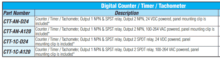
Ordering Information:
Every unit is a counter, timer or tachometer. You select the mode that is required for your application. All units come with a NPN and SPST relay contacts on CTT output 1. Output 2 on the CTT can be ordered as a NPN or SPST relay contact.
CTT-AN = Output 2 NPN
CTT-1C = Output 2 SPST relay contact
The supply voltage can be either 24VDC (-D24) or 100-264VAC (-A120). This gives us a combination of 4 different units to choose.
Watch on YouTube : CTT Counter Timer Tachometer – Un-boxing the CTT
Dimensions
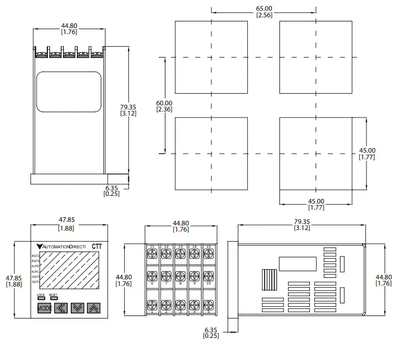
mm [inches]
1/16 DIN size (48 x 48 mm)
Wiring
Here are the wiring diagrams for all four units.
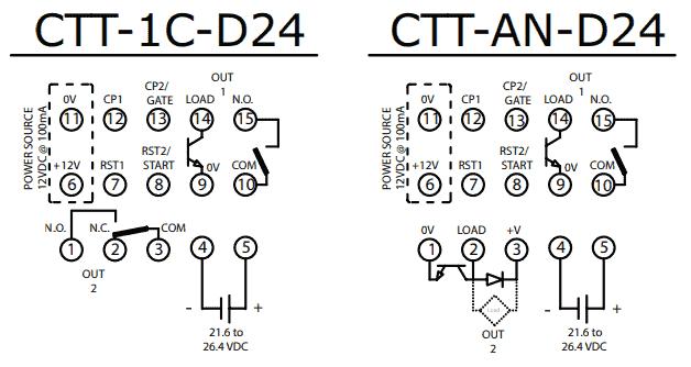
The 24DC power supply units side by side. Notice that the only difference is output 2. One is NPN and the other is SPST relay.
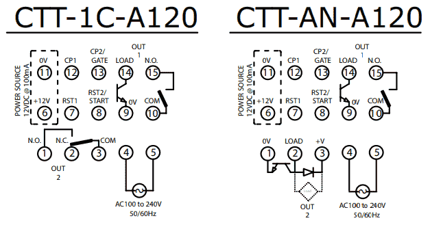
The AC power supply can be anywhere from 100 to 240 VAC. Note that output 2 is the same options as the DC version.
Display, Indicators, and Keys
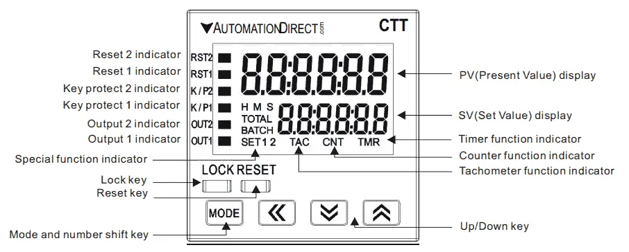
Reset 2 / 1 indicator – Light on when reset signal is detected
Key protect 2 / 1 indicator – Light on when key-protected mode is enabled
Output 2 / 1 indicator – Light on when output is executing
H M S – Hour, minute, second unit of timer displayed in Timer function
TOTAL – “Total Counting Mode” in Counter function
BATCH – “Batch Counting Mode” in Counter
SET 1 2 – SV1, SV2 display – Set Value
TAC – Light on in Tachometer function
CNT – Light on in the Counter function
TMR – Light on in Timer function
Note: See the video below for the operation of the front panel.
CTT Functions
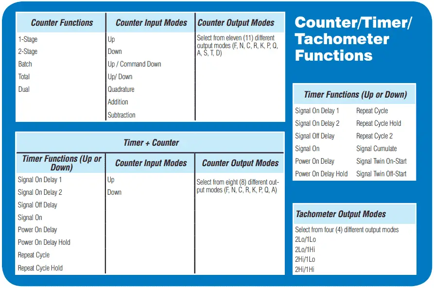
CTT Series Programming
Programming of the CTT Series can be done with DIP switches or the lockable keypad on the unit. You can choose the way your unit will function by looking at the timing chart diagrams for each of the different modes. The following two posts will explain the timing chart diagrams and how to read them.
The Secret of Using Timers – Video
The Secret of Using Counters – Video
Here is an example of the timing charts for the CTT Series.
Watch on YouTube: CTT Counter Timer Tachometer – Powering the Unit
Summary of CTT features
– Can operate as a digital counter, timer, combination timer + counter, or tachometer
– Accepts voltage and non-voltage inputs from a wide variety of NPN, PNP, or dry contact sensors
– Selectable counting speeds from 1 to 10,000 cycles per second
– Multiple transistor and relay outputs can operate as momentary or maintained
– Double-line, 6-digit, 2-color LCD display
– Easy configuration with externally accessible DIP switches or the lockable keypad
– Display decimal point selection
– Available in 100-240VAC and 24VDC powered models
– UL508 listed (E311366), cULus, CE marked
Counter, Timer, Tachometer – CTT Series from Automation Direct
Shop Multi-Function Digital Counter / Timer / Tachometer
CTT Overview
https://cdn.automationdirect.com/static/specs/cttcountertimertachoverview.pdf
CTT Quick Start Guide
https://cdn.automationdirect.com/static/manuals/cttqsg/cttseries_qsg.pdf
Digital CTT Manual
https://cdn.automationdirect.com/static/manuals/digitalctt/digitalctt.html
Rhino Power Supply
https://www.automationdirect.com/adc/Overview/Catalog/Power_Products_(Electrical)/DC_Power_Supplies
https://cdn.automationdirect.com/static/specs/pslpowersupplies.pdf
Next time we will look at the programming of the timer mode in the CTT.
If you have any questions or need further information please contact me.
Thank you,
Garry
If you’re like most of my readers, you’re committed to learning about technology. Numbering systems used in PLC’s are not difficult to learn and understand. We will walk through the numbering systems used in PLCs. This includes Bits, Decimal, Hexadecimal, ASCII and Floating Point.
To get this free article, subscribe to my free email newsletter.
Use the information to inform other people how numbering systems work. Sign up now.

The ‘Robust Data Logging for Free’ eBook is also available as a free download. The link is included when you subscribe to ACC Automation.