The MOSAIC Modular Safety Integrated Controller can be programmed for your safety control application. Steps to programming our MOSAIC include writing the program, verification, simulation, downloading and monitoring. We will be looking at the E-STOP instruction part of our program.
Our first program included writing, verifying, simulating and monitoring our MOSAIC Safety emergency stop switch and status indication. (feedback) We will now modify our E-STOP in our circuit and discuss redundancy, short circuit protection, and manual reset. Let’s get started.
Previously in this MOSAIC Safety Controller Series, we have discussed:
MOSAIC Safety Controller System Hardware
– System Hardware Un-boxing Video
– System Hardware Powering Up Video
Installing the Software (MSD) – Video
First Program Part 1 – Video
First Program Part 2 – Video
Documentation – Video
We will use the program we developed previously.
Note: As mentioned before, we are expanding on our simple program to show features of the Safety Controller.
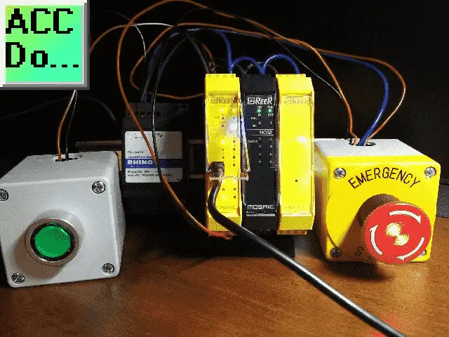
Watch the video below to see the emergency stop in action on the MOSAIC Safety Controller.
The examples and diagrams included in this post are solely for illustrative purposes. Due to the many variables and requirements associated with your particular installation, ACC Automation cannot assume responsibility or liability for actual use based on the examples and diagrams.
E-Stop (Emergency Stop)
Emergency stop pushbutton inputs usually have the following specifications:
– Electric contacts must have a direct opening action. Normally closed contacts.
– Emergency stop devices must have a holding function that will mechanically hold in the stop position until the device is manually reset.
– Actuators of an emergency stop device must be coloured red and of a mushroom shape.
– The background immediately behind the actuator must be coloured yellow.
The following are the specifications that we can use when programming our E-STOP with our MSD Mosaic Software Designer.
Input Type – Emergency Stop Safety
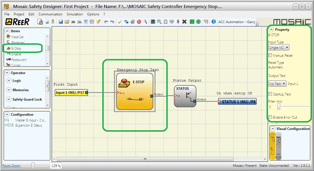
Select the E-Stop in the work area. This will display the property window on the right side of the Mosaic Safety Designer (MSD) window. The input type can be set for Single NC or Double NC.
Single NC – This will allow the wiring of a one-way emergency stop, normally closed contact from the switch. (Single set of NC contacts.)
Double NC – This will allow the wiring of a two-way emergency stop, normally closed contacts from the switch. (Two sets of NC contacts.)
The double NC selection will call up the ‘With simultaneity’ option. If selected, this activates the test to verify the concurrent switching signals coming from the contacts of the emergency stop. Time can be set in milliseconds to determine the maximum amount of time allowed between the two contact signals.
In our example, we will be using the Single NC input type.
Manual Reset – Safety Emergency Stop
Selecting this option will force the user to reset each time the emergency stop is activated. If not selected, the output will directly follow the input condition.
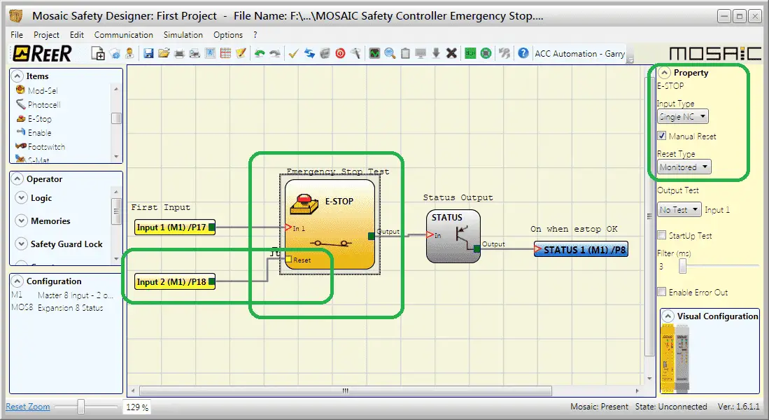
Reset Type
The reset type can be selected for manual or monitored.
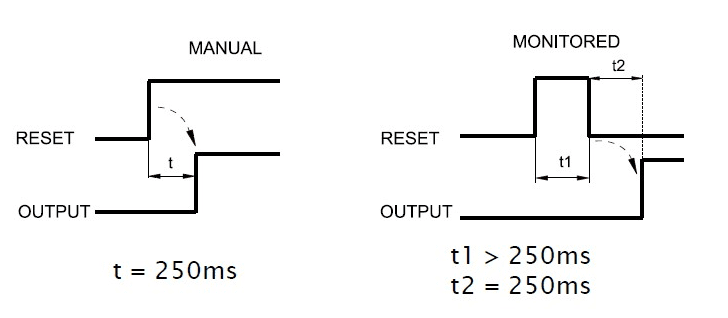
If the manual is selected the safety controller will look for a signal from off to on. The on-time must be a minimum of 250 milliseconds. Monitored reset tells the safety controller to look for a signal from off to on and then off again. The signal must be on and then off again for 250 milliseconds each. So it will take half a second to reset the emergency stop instruction.
In our example, we will be using a monitored reset input.
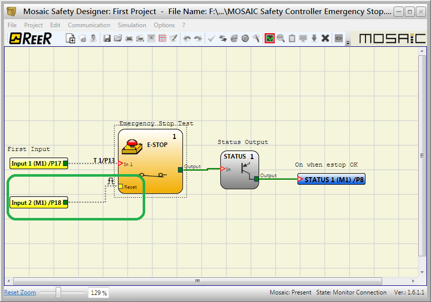
Note: A consecutive input must be used for the reset input. In our case input 2, is used because input 1 is our Single NC emergency stop input.
Output Test – Emergency Safety Stop
The output test is used to select which test output signals are to be sent to the emergency stop (mushroom pushbutton). This additional test makes it possible to detect and manage any short-circuits between the lines. There are four test outputs on the M1 Mosaic Safety Controller.
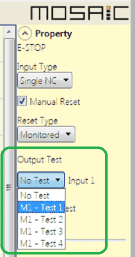
The test output sends a pulse train through the circuit to expects to the same when internally monitoring the signal. If the input is held high it will produce an error, or if a break occurs in the wire.
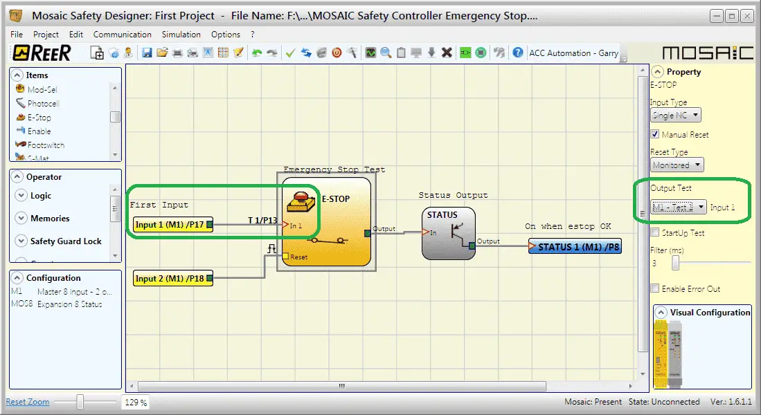
We will use M1-Test for our output test. Notice that the schematic now shows Test 1 Pin 13 (T1/P13) for the wiring of the test one.
StartUp Test – Emergency Stop
When StartUp Test is selected it enables the test at start-up of the external component (emergency stop). This test is performed by pressing and releasing the pushbutton to run a complete function test and enable the output. This test is only requested at machine start-up when power is first applied or the reset is done by the software.
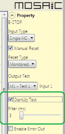
Filter (ms) – Emergency Stop
Filter (ms) is used to filter the signals coming from the emergency stop. The filter can be configured between 3 and 250 ms and eliminates any bouncing on the input contacts. The length of the filter affects the calculation of the unit’s total response time.
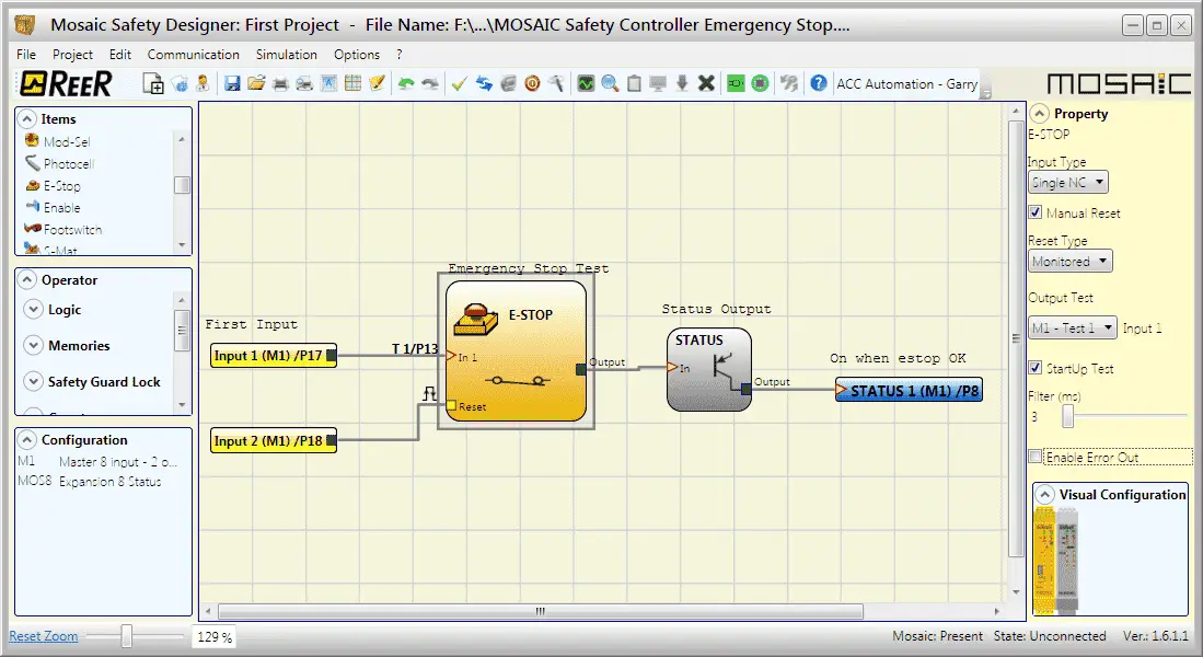
Here is our completed circuit.
We can now verify our program.
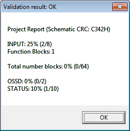
This is done by selecting the checkmark icon on the main screen of the MSD software.
Simulator – Safety Emergency Stop
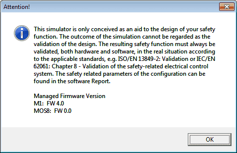
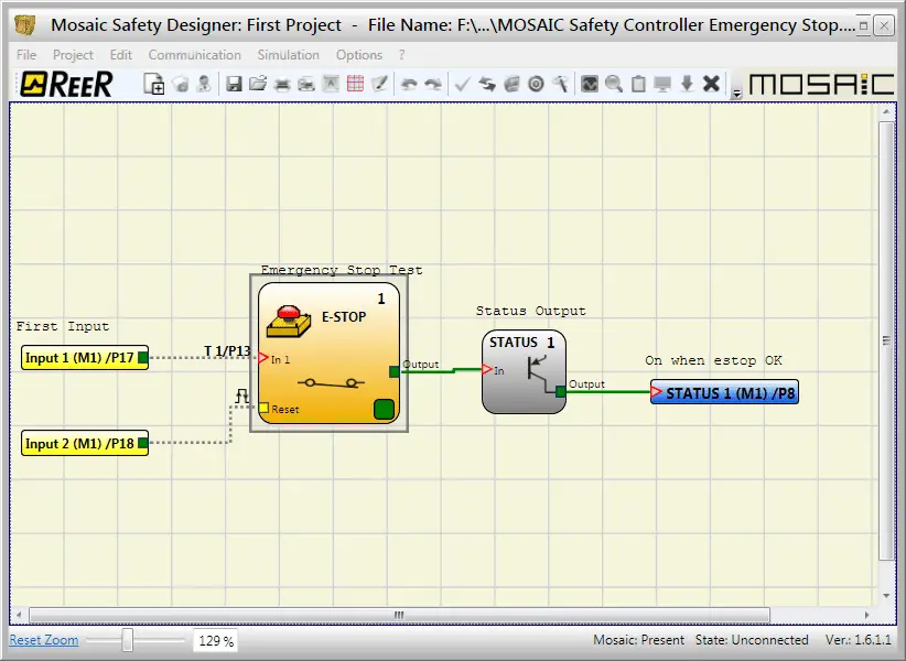
The simulator will allow us to see the logic while we turn off and on the E-STOP instruction.
Note: The reset cannot be simulated. We will be now transferring the configuration and testing on our actual equipment.
Connect the MOSAIC Safety Controller
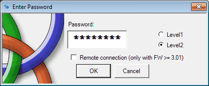
The default password for level2 (Programming) is ‘SAFEPASS’. This is all capital letters.
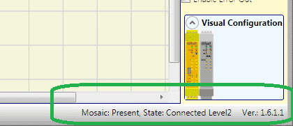
The bottom right corner of our MSD Software will indicate the status of our system.
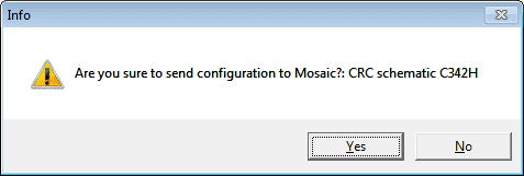
Send the configuration to the MOSAIC Safety Controller. Click Yes.
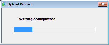
Our program will now be transferred to the controller.
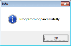
Upon completion of the transfer will get a notification that the programming was successful. Click OK.
Select the Disconnect / Restart icon on the main menu of the MSD software. This will reset our safety controller.
Monitoring our Program
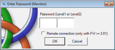
Select the graphical monitor icon on the main menu to start monitoring our program. Since there is no default password for level 1 hit OK.

We are now monitoring our program. The solid red line on the output indicates that we have an emergency stop condition and it is still active. (Held ON)
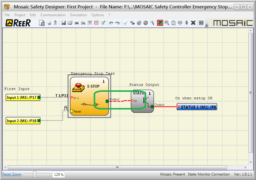
Physically resetting our emergency stop switch will change the solic red line on the output to a dashed line.
Holding our reset on for at least 250 milliseconds and then off will reset our E-STOP and the output status will be on. The indication is a solid green line.
Wiring Diagram for our Program – Emergency Safety Stop
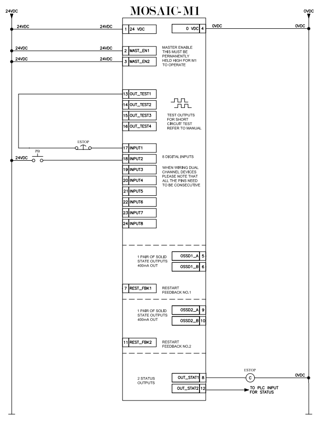
Here is the complete wiring of our M1 controller to our Emergency Stop Pushbutton and Reset Pushbutton.
Watch the video below to see the verification of the program with our documentation on the MOSAIC Safety Controller.
Download the program here.
ReeR MOSAIC Safety Controller (Automation Direct) Advantages:
- Reduces the number of devices and wiring used and overall size of the project
- Speeding-up control panel construction
- Allows tamper-proof system configurations
- All logic is configured through a graphic interface
(no more laborious wiring is needed as with traditional solutions) - The lower number of electromechanical components also means a better performance level and a higher safety level
- The project report provides the actual values of PFH, DCavg, and MTTFd according to EN 13849-1 and EN 62061
ReeR MOSAIC Safety Controller
MOSAIC Controller Installation and Use Manual
MOSAIC Field bus Modules: Installation and Use
Supplemental Communication information and example wiring diagrams
Product Datasheets (Installation and Setup Instruction)
MSD – MOSAIC Safety Designer Software – (Free Download Link) – The software will contain all of the instruction sets and help files for the MOSAIC Safety Controller.
Next time we will look at our Output Signal Switching Device OSSD on the MOSAIC Safety Controller.
Watch on YouTube: MOSAIC Safety Controller Emergency Stop
If you have any questions or need further information please contact me.
Thank you,
Garry
If you’re like most of my readers, you’re committed to learning about technology. Numbering systems used in PLC’s are not difficult to learn and understand. We will walk through the numbering systems used in PLCs. This includes Bits, Decimal, Hexadecimal, ASCII and Floating Point.
To get this free article, subscribe to my free email newsletter.
Use the information to inform other people how numbering systems work. Sign up now.

The ‘Robust Data Logging for Free’ eBook is also available as a free download. The link is included when you subscribe to ACC Automation.