The C-More HMI Panel software uses virtual components called Objects. These objects are programmable to simulate the functions that you require on your automation project. Pushbuttons, Switches, meters, and graphs are just a few of the objects that are available to you.
A bitmap is an image file format used to store digital pictures (images). The extension used to represent a bitmap file is BMP.
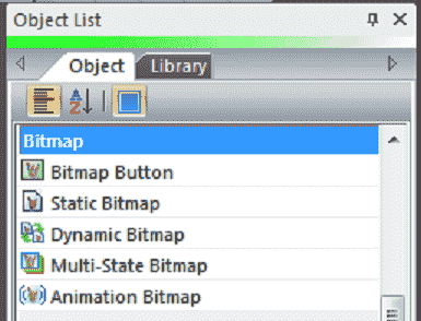
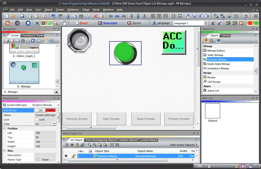
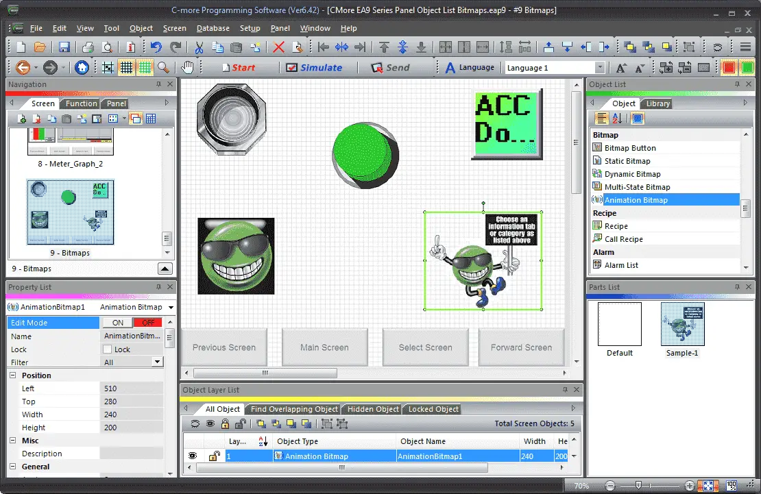
We will now look at the object list bitmaps that we can use with our C-More HMI panel. The bitmap objects that are available on the C-More EA9 are Bitmap Button, Static Bitmap, Dynamic Bitmap, Multi-State Bitmap, and Animation Bitmap. Let’s get started.
Previously in this C-More EA9 HMI Panel series, we have done the following:
System Hardware
– Unboxing and Review Video
– Powering the Unit Video
Installing the Software – Video
System Setup Screens – Video
First Program
– Establishing Communication and Updating Firmware Video
– First Program Video
Panel to PLC and PLC to Panel Settings – Video
Common Screen Menu – Video
Simulate Project – Video
Object List Shapes – Video
Object List Buttons – Video
Object List Indicators – Video
Object List Entry – Video
Object List Meters and Graphs – Video
Watch the video below to see the Object List Bitmaps in action on our C-More EA9 HMI Panel.
Setting Our C-More Object Bitmap Screen
We will be adding to the program we created last time. (C-More EA9 HMI Series Panel Object List Meters and Graphs).
Select the new screen under the main menu | Screen | New Screen…
Alternatively, we can also use the icons in the Navigation panel.
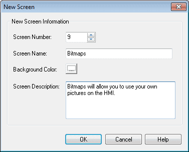
We will name screen 9 Bitmaps. The screen description can be used to describe the screen. Hit OK.
Our new screen will now be displayed.
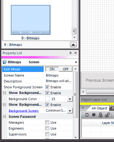
Under the property, list window turn on the editing and enable the show background. Select Common Screen Menu under the background screen. Turn off the edit mode under the property list.
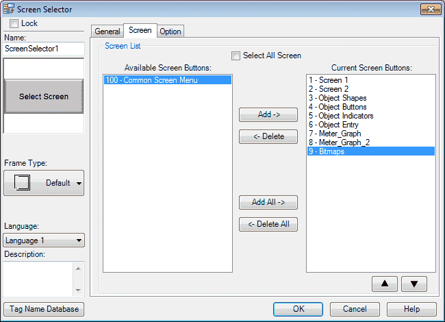
We must now add our new screen so we can select it when using the common screen menu. Select page 100. Select the Screen Selector button. Under the Screen tab, select the 9 – Bitmaps and hit the Add button so it moves it over to the Current Screen Buttons. Hit OK. We can now go back to our newly created Object Bitmap screen page 9 from our navigation window.
Our new screen is now ready for us to add our indicators.
C-More Object Bitmaps Tag Name Database
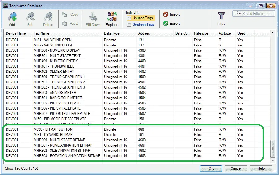
We will use the following addresses to control the Bitmap objects on the cmore HMI.
MC60 – Discrete – Modbus Address 00060 – Read / Write (Bitmap Button)
MI61 – Discrete – Modbus Address 10061 – Read (Dynamic Button)
MHR600 – Unsigned Int 16 – Modbus Address 40600 – Read / Write (Multi-State Bitmap)
MHR601 – Unsigned Int 16 – Modbus Address 40601 – Read / Write (Move Animation Bitmap)
MHR602 – Unsigned Int 16 – Modbus Address 40602 – Read / Write (Size Animation Bitmap)
MHR603 – Unsigned Int 16 – Modbus Address 40603 – Read / Write (Rotation Animation Bitmap)
C-More Bitmap Objects
Bitmap images are used to display visually the values in the PLC. It will allow you to communicate better with the operator through your C-More HMI screens. This will make your screens more intuitive. Images can be sequenced, sized, moved and rotated on the C-More HMI screen. The control of these tags is done with the C-More HMI panel and communicated to the PLC program.
C-More Bitmap Button
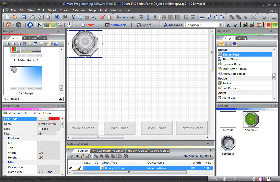
Select Screen 9 from the navigation window. We will now add a Bitmap Button under the Bitmap heading in the Object list window. Left-click (hold) and drag the Sample-2 under the Parts List for the Bitmap Button onto the screen.
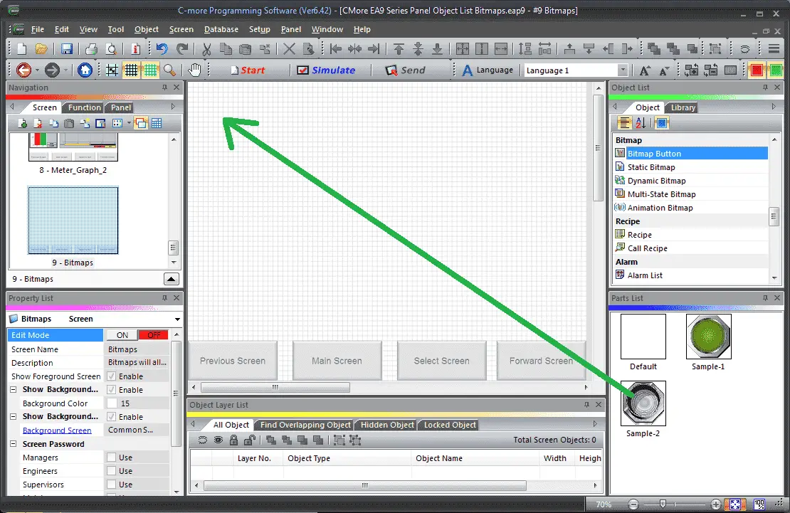
Note: Choose a preconfigured part from the Parts List window for the object selected. This will save time when configuring objects. Click and drag the item from the parts list to the screen. All of the objects will have a parts list.
The Bitmap Button window will display. You can also use the main menu | Object | Bitmap | Bitmap Button… and click on the work area of the screen. This will give you the default bitmap button selection.
The following parameters can be set:
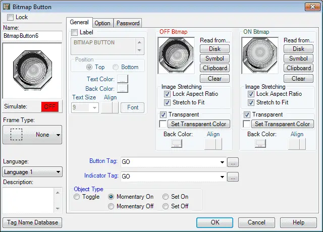
Name: This is the name of the object. The default is BitmapButton6
Object Preview Window: This will show what the object will look like on the screen.
Frame Type: The line trend graph object can be displayed in a series of frames. We will leave this as the default value.
Language: We will leave this as our default Language 1.
Description: We can enter up to 400 words to describe the purpose of the bitmap button that we are programming.
Tag Name Database: This will open a window that allows you to add, edit, or delete tag names.
General Tab
Label: This will add a label to the bitmap button. We will not select this and leave the default name of the BITMAP BUTTON in the label text field.
OFF Bitmap: This is the bitmap that is displayed when the indicator tag is off. The bitmap can be obtained by reading this from the Disk, Symbol, or Clipboard (Windows Copy). You can also clear the bitmap image by selecting clear. We will leave this as the default image.
ON Bitmap: This is the bitmap that is displayed when the indicator tag is on. The bitmap can be obtained by reading this from the Disk, Symbol, or Clipboard (Windows Copy). You can also clear the bitmap image by selecting clear. We will leave this as the default image.
Image Stretching can be set for both the ON and OFF bitmaps:
Lock Aspect Ratio – will ensure that the image will not be distorted from the original. This is selected as the default.
Stretch to Fit – will ensure that the image takes up the space you have selected.
Transparent – This can be set for both the on and off bitmaps. You can set individual colours in the bitmap to be transparent on the C-More HMI display screen. We will leave this as the default white colour.
Button Tag: MC60 – Bitmap button – This is the bit in the PLC that will trigger when the image is pressed.
Indicator Tag: MC60 – Bitmap Button – This is the bit in the PLC that will trigger the image changed. In our case, this is the same as the bitmap button so that they will work together.
Object Type:
This allows us to choose between five types of operation for the pushbutton object. We will leave this as the default of toggle.
– Toggle: The toggle will alternate between ON and OFF every time the pushbutton is pressed. This will be our selection.
– Momentary On: The pushbutton will be on when the pushbutton is being pressed. As soon as the button is released it turns to the OFF state.
– Momentary Off: The pushbutton will be off when the pushbutton is being pressed. As soon as the button is released it turns to the ON state.
– Set On: The state of the pushbutton will be ON when pressed. It will remain ON until a separate device like another pushbutton or signal from the PLC turns it OFF.
– Set Off: The state of the pushbutton will be OFF when pressed. It will remain OFF until a separate device like another pushbutton or signal from the PLC turns it ON.
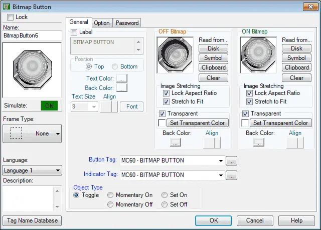
Here is our completed general tab.
Select the Options tab.
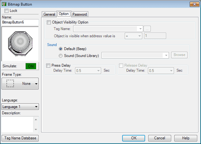
Option Tab
Object Visibility Option: We can use this selection to configure a tag to control when the object appears on the screen. C-More EA9 HMI Series Panel Object List Shapes – Video will demonstrate how we use this option.
Sound: Default (Beep) – We can also select a specific sound when the operator selects our bitmap button.
Press Delay – This can be used to eliminate faults triggering of our bitmap button. This time delay will have to be met before the tag bit will change state. We will leave this as the default off.
Select the Password tab.
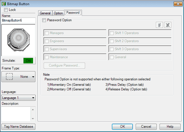
Password options can be set for this object. We will leave this off.
Click OK.
We can now position and resize the bitmap button object on our screen using our mouse.
C-More Static Bitmap
The static bitmap is used to put an image on your C-More EA9 HMI screen.
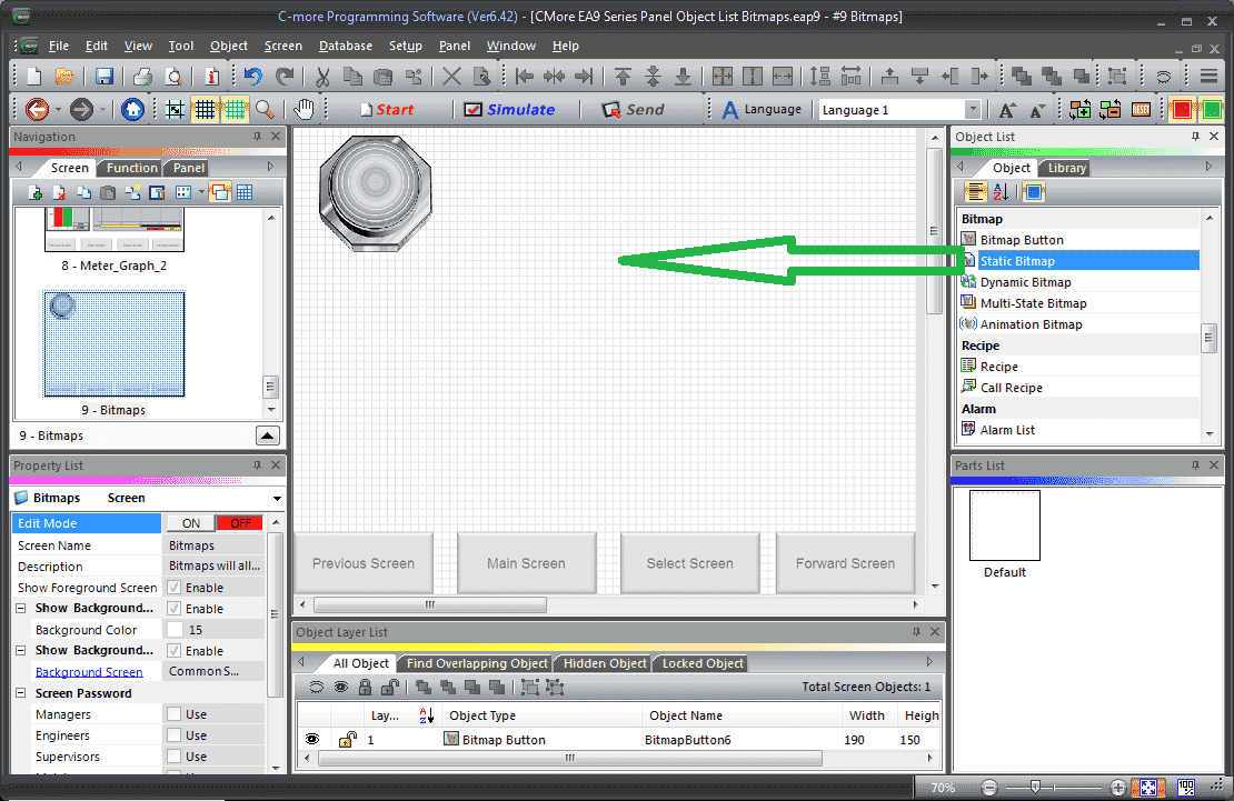
Select Static Bitmap from the Object List under Bitmap. Now click and hold Default from the parts list and drag onto our screen.
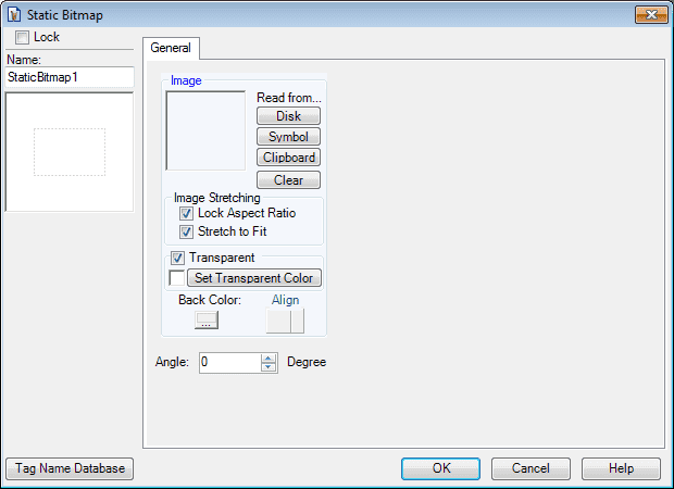
The Static Bitmap window now appears. This is similar to many of the items that we have already programmed previously above.
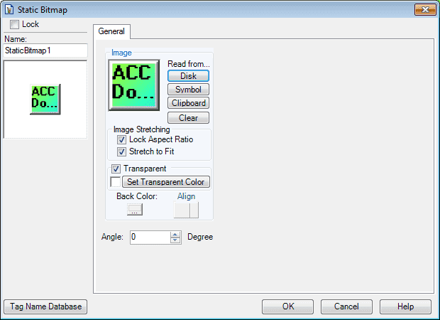
Select read from disk to choose the bitmap (.BMP) image that you would like to display.
The image stretching and transparency is the same as the bitmap button above.
The angle can be set in degrees to rotate your image. We will leave this as its default of 0.
Select OK.
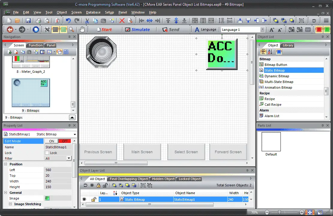
We can now use the mouse and size and move our static bitmap object.
C-More Dynamic Bitmap
The Dynamic Bitmap Object is used to display an image from a tag based on its ON or OFF state. We will now add a dynamic bitmap that will look like a 3D pushbutton.
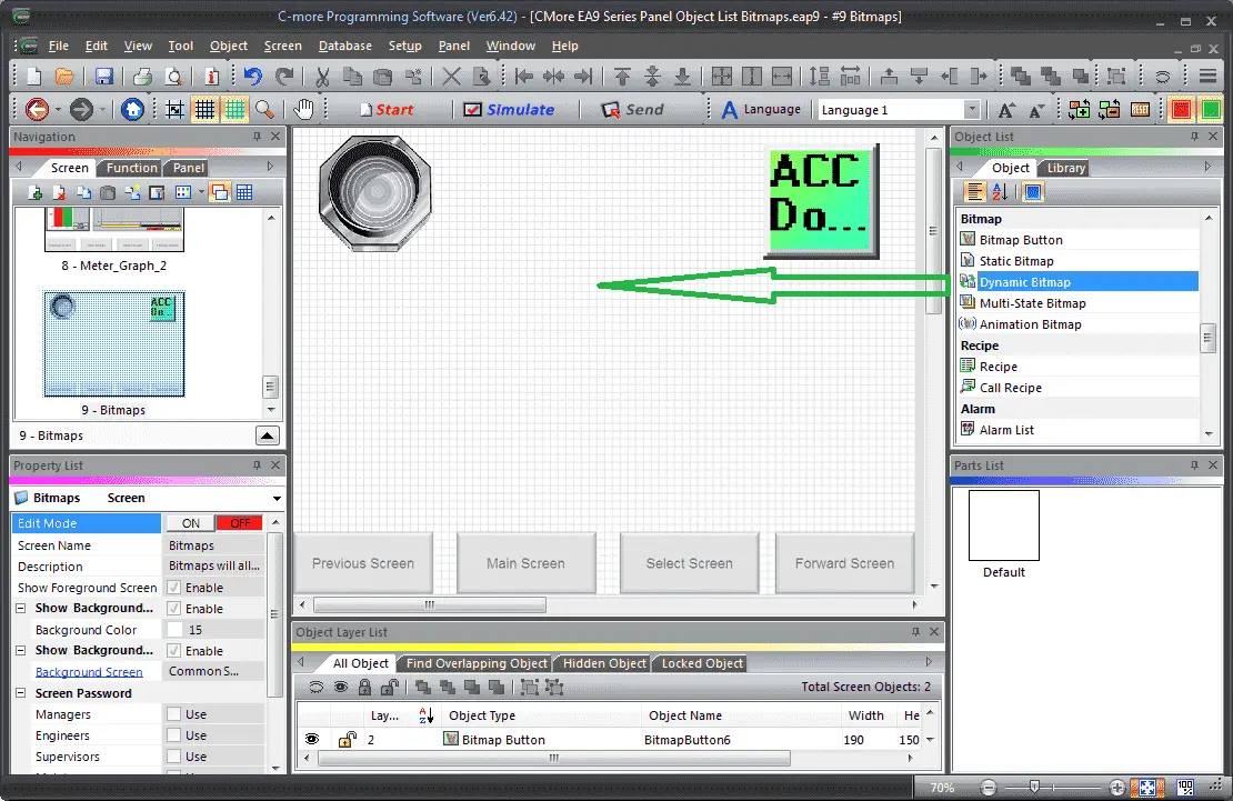
Select Dynamic Bitmap from the Object List under Bitmap. Now click and hold Default from the parts list and drag onto our screen.
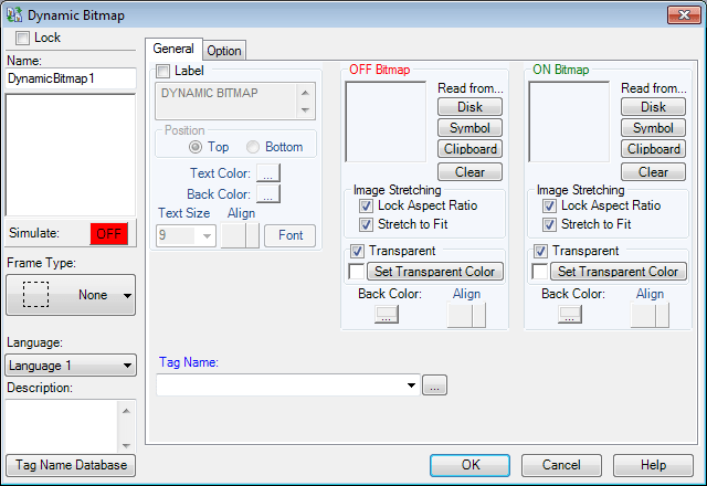
The dynamic bitmap window will now appear. This object is very similar to what we have programmed above.
Selecting Read from Symbol will call up the Symbol Factory. The Symbol Factory is a library of over 5,000 graphics optimized for high performance for use in industrial automation C-More HMI applications, including pumps, pipes, valves, tanks, mixers, motors, ducts, electrical symbols, flow meters, material handling, sensors, PLCs, transmitters, and ISA symbols. This was installed during the installation of the C-More software.
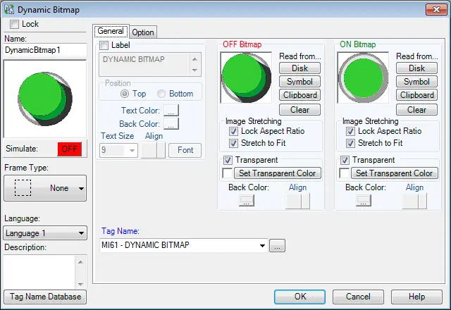
We will use the 3D green pushbutton for our images on the dynamic bitmap.
We will leave everything as the default except for our tag name.
Our Tag Name will be set for MI61 (Modbus Address 00061). Note: This is a read-only bit from the PLC.
Select the options tab.
Option Tab
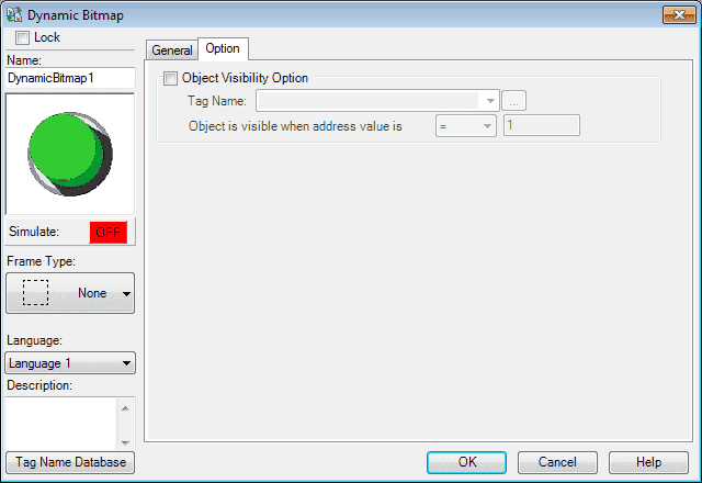
We will not use visibility.
Select OK
We can now use the mouse and size and move our dynamic bitmap object.
C-More Multi-State Bitmap
A multi-state bitmap is used to display images based upon a number or a bit location within a tag in the PLC. In our case, we will display 5 images based upon the tag location number. (0 to 4)

Select Multi-State Bitmap from the Object List under Bitmap. Now click and hold Default from the parts list and drag onto our screen.
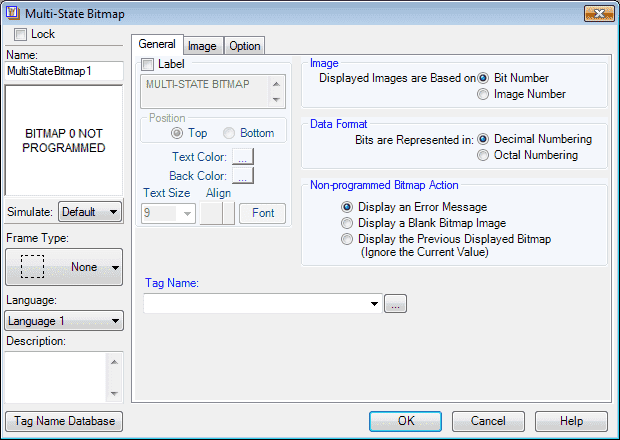
The Multi-State Bitmap window will now appear.
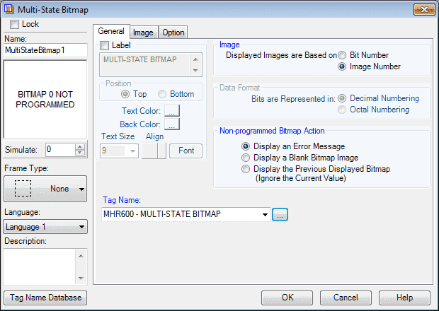
We will leave most of the settings on default. Our tag name will be set as follows:
Tag Name: MHR600 (Modbus Address 040600) – Multi-State Bitmap
Displayed images are based on an image number.
Non-programmed bitmap action will display an error message.
Select the Image tab.
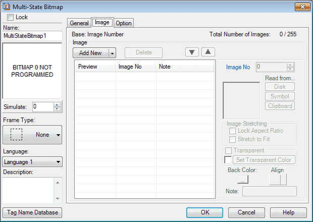
We can now use the Add New button to add the images and properties that we need for each of the images.
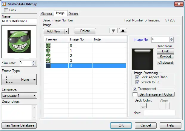
This is our programmed screen. You will note that we can have 255 images in the table.
Select the options tab.
Option Tab
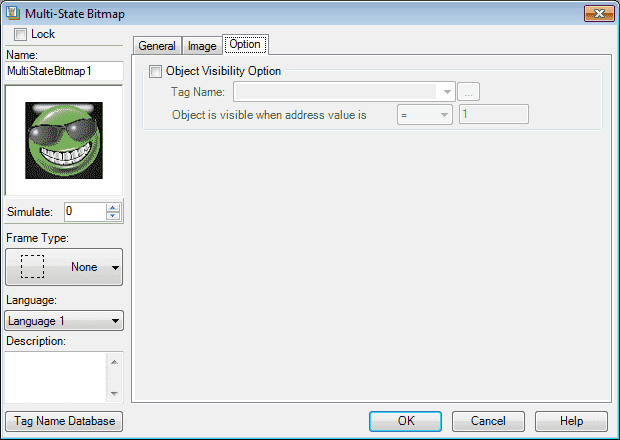
We will not use visibility.
Select OK.
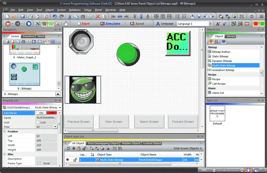
We can now use the mouse and size and move our multi-state bitmap object.
C-More Animation Bitmap
The Animation Bitmap will allow you to place an image (.BMP) on the C-More HMI screen and move, size, and rotate it. This is accomplished through tags that reference addresses in the PLC.
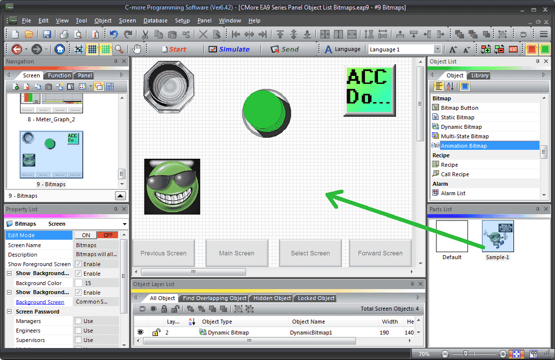
Select Animation Bitmap from the Object List under Bitmap. Now click and hold Sample-1 from the parts list and drag onto our screen.
The animated bitmap window will now appear.
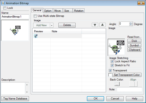
We will leave all of the general tab settings as their default.
Select the options tab.
Option Tab
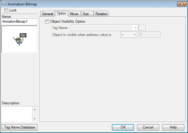
We will not use visibility.
Select the move tab.
Move Tab
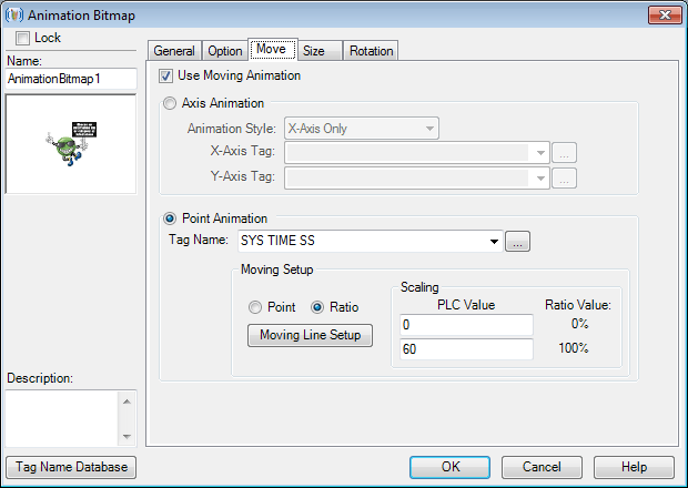
Ensure that the ‘Use Moving Animation’ selection is checked. Currently, we are using point animation with a tag name for the internal system clock for seconds. So the original intent of this was to move the image around to different locations based on 60 seconds.
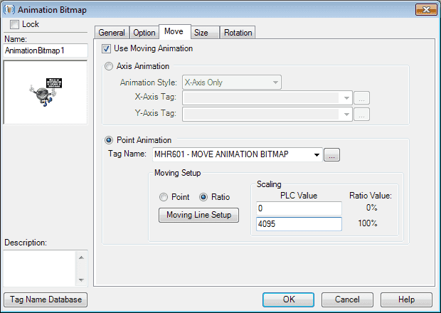
We will use the following tag name:
MHR601 – (Modbus Address 040601) – Move Animation Bitmap
We will keep the moving setup to ratio and change the scaling value to the following. PLC value 0 – 4095 = Ratio Value 0 – 100%
Select the ‘Moving Line Setup’
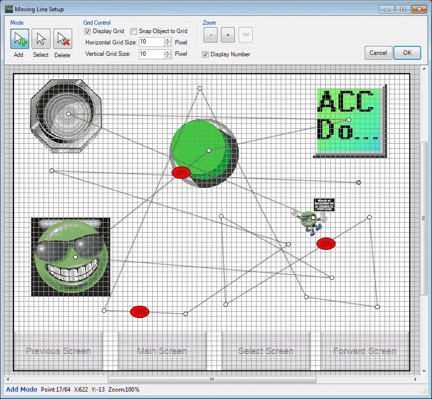
We can now use the mouse and map out our line ratios for the image movement.
Select OK
Select the size tab.
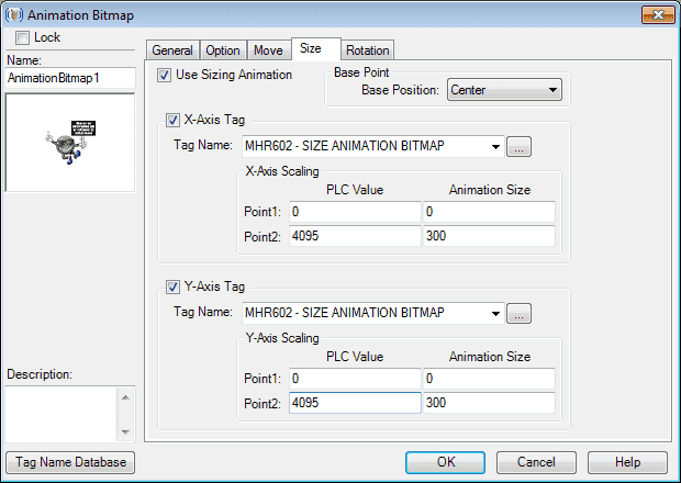
Size Tab
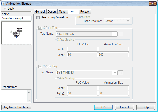
Select ‘Use Sizing Animation’.
The X-Axis Tag and the Y-Axis Tag will be equal. This way the image will grow proportionally.
Tag Name: MHR602 – (Modbus Address 040602) – Size Animation Bitmap
Scaling factors will be set for PLC 0 – 4095 = 0 – 300 Animation Size
Select the rotation tab.
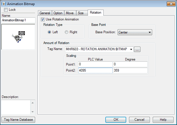
Rotation Tab
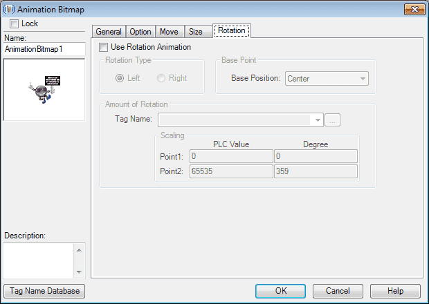
Select ‘Use Rotation Animation’.
The rotation type will be left with the base point position will be center.
Amount of Rotation
Tag Name: MHR603 – (Modbus Address 040603) – Rotation Animation Bitmap
Scaling factors will be set for PLC 0 – 4095 = 0 – 359 Degrees
Select OK
We can now use the mouse and size and move our animated bitmap object.
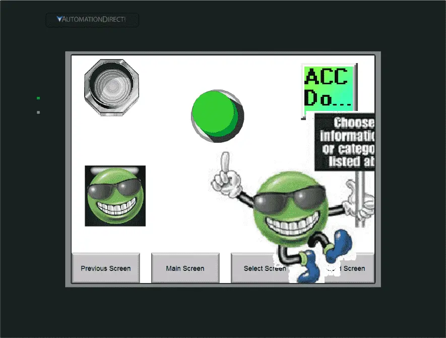
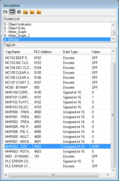
Simulate our Project – C-More Object Bitmaps
We can use the simulator to view and try our bitmap objects. This will ensure the visual and address operations that we want in our program.
PLC Program Additions
Using the program we previously developed, we will add additional rungs to control the bitmap objects that we have just created.
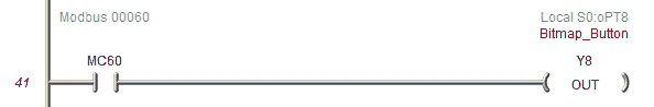
Turn on output Y8 when our input button is touched on the C-More EA9 HMI.
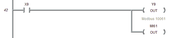
When X9 is turned on in the simulator, the dynamic bitmap will change the image on our EA9 HMI. Output Y9 will also be active.
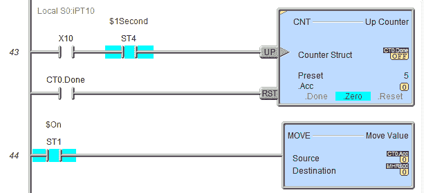
The multi-state bitmap is controlled by a counter. This counter will count from 0 to 4 and then automatically reset. This counter is activated by X10 in series with a 1-second system contact.
The current counter value is then placed in the MHR600 register to indicate what image to show on the multi-state bitmap object.
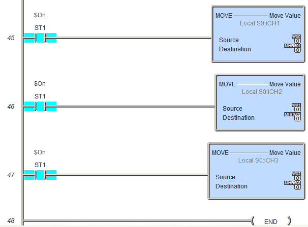
Move WX0 to address MHR601 (Modbus 40601). WY0 has a range from 0 to 4095. This will control the movement of our Animation Bitmap Object.
Move WX1 to address MHR602 (Modbus 40602). WY1 has a range from 0 to 4095. This will control the size of our Animation Bitmap Object.
Move WX2 to address MHR603 (Modbus 40603). WY2 has a range from 0 to 4095. This will control the rotation of our Animation Bitmap Object.
Note: Our scaling is all done in the EA9 HMI.
Download the PLC and C-More program here.
Watch the video below to see the Bitmap Objects in action on our C-More EA9 HMI Panel. This will also demonstrate the PLC ladder code for functionality.
C-More EA9 Panels from Automation Direct
https://www.automationdirect.com/c-more/home
C-More – Graphic Panel (EA9 Series) User Manual and Quick Start Guides
https://cdn.automationdirect.com/static/manuals/ea9userm/ea9userm.html
EA9-T10CL C-More Specifications
https://cdn.automationdirect.com/static/specs/ea9t10cl.pdf
C-More EA9 Programming Software (Current Version V6.42)
https://support.automationdirect.com/products/cmore.html
This software will enable you to program all of the C-More EA9 HMI units. It includes a simulator for your application.
Next time we will look more at the object list recipes that we can use in the C-More HMI Panel.
Watch on YouTube: C-More EA9 HMI Series Panel Object List Bitmaps
If you have any questions or need further information please contact me.
Thank you,
Garry
If you’re like most of my readers, you’re committed to learning about technology. Numbering systems used in PLC’s are not difficult to learn and understand. We will walk through the numbering systems used in PLCs. This includes Bits, Decimal, Hexadecimal, ASCII and Floating Point.
To get this free article, subscribe to my free email newsletter.
Use the information to inform other people how numbering systems work. Sign up now.

The ‘Robust Data Logging for Free’ eBook is also available as a free download. The link is included when you subscribe to ACC Automation.