The MOSAIC Modular Safety Integrated Controller can be programmed for your safety control application. Steps to programming our MOSAIC include writing the program, verification, simulation, downloading, and monitoring.
We will be using the MOSAIC Safety Designer software (MSD) to write, verify, and simulate our program. Our first program will have an emergency stop switch with a status indication. Let’s get started.
Previously in this MOSAIC Safety Controller Series, we have discussed:
MOSAIC Safety Controller System Hardware
– System Hardware Un-boxing Video
– System Hardware Powering Up Video
Installing the Software (MSD) – Video
The examples and diagrams included in this post are solely for illustrative purposes. Due to the many variables and requirements associated with your particular installation, ACC Automation cannot assume responsibility or liability for actual use based on the examples and diagrams.
Start the MSD Software – MOSAIC Safety Designer
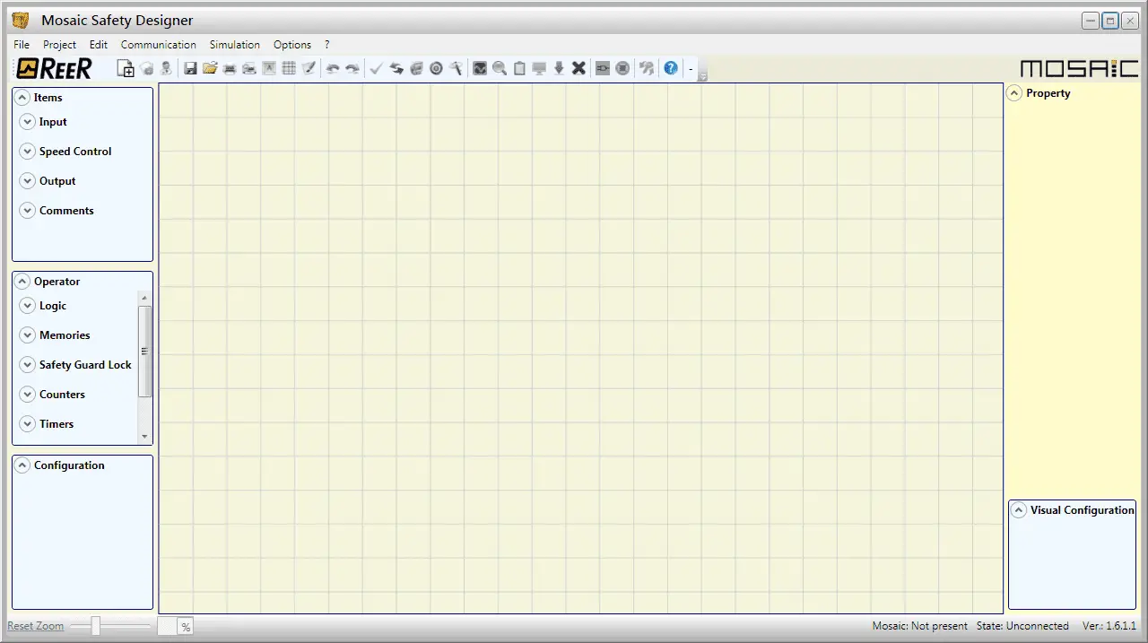
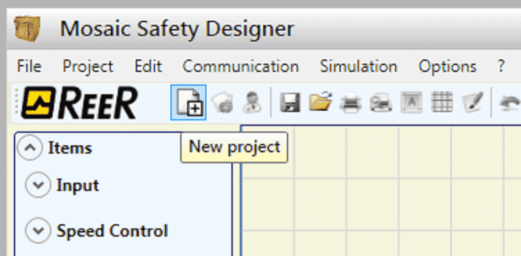
Call up our MSD (MOSAIC Safety Designer) software by double-clicking on the desktop icon or from your windows menu | All Programs | ReeR Mosaic Safety Designer | MSD. This MSD software was installed last time. See the above post.
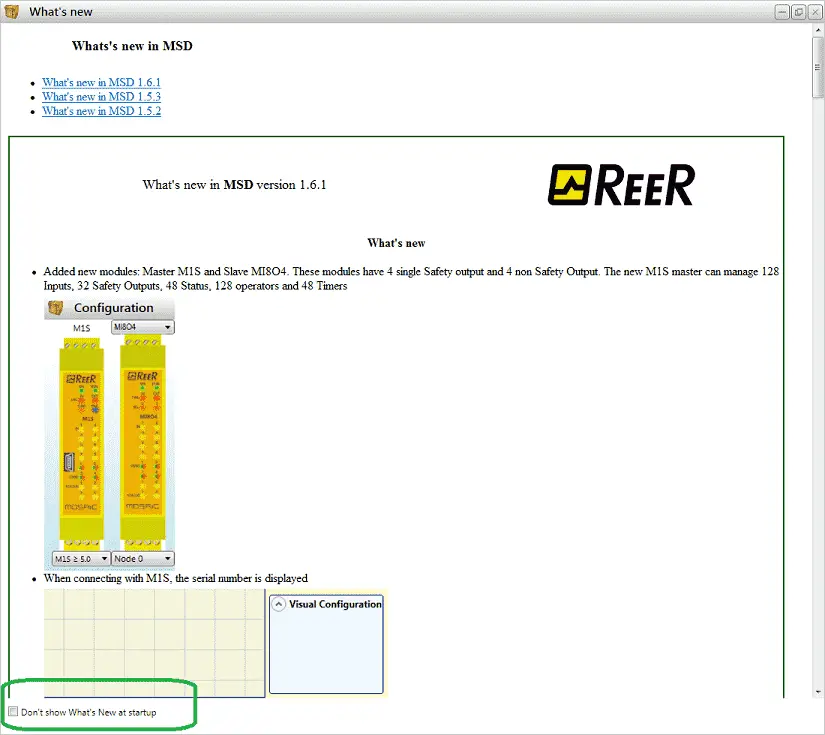
The “What’s new” window will now be displayed. This will tell you all about the new features of this version. The checkbox can be selected at the bottom of the window to not show “What’s New” at startup. This can also be selected under the Options menu on the main menu. Hit the X in the top right corner to close the window.
Starting a New Project – MOSAIC Safety Controller Program
To start a new project you can select New Project under the Project title in the main menu. Alternatively, you can select the New Project icon on the main screen.
The project information window is now displayed.
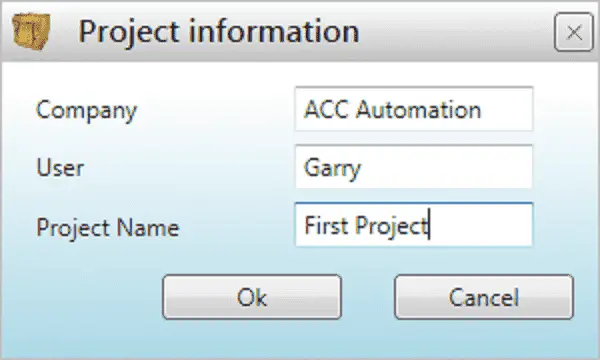
We will fill in the Company, User and Project Name for our application. (First Project)
Select OK.
Configuration of the System – MOSAIC Safety Controller
The Configuration window will now be displayed.

This is where we will fill in our hardware configuration so that the controller will know what is connected to our bus system.
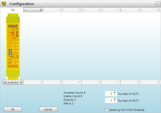
Change the M1S controller to the M1 controller. We have selected the version number of the controller between 4.0 and 5.0. Currently, we do not know the correct version until the connection to the actual hardware.
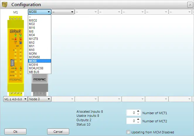
Select the MOS8 for the next card on the bus system. (8 point status output) Leave Node 0 as the default for this card. You will see that there is a summary of our configured system.
Allocated Inputs: 8
Usable inputs: 8
Outputs: 2
Status: 10
Note: Our MR2 safety relay output does not require the bus system so this is not included in our configuration.
Select OK.
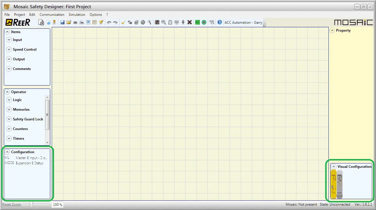
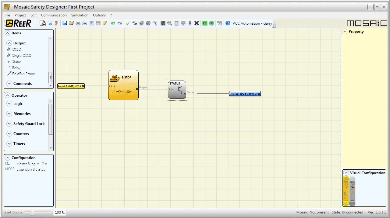
Our main page will reflect visually our configuration on the bottom right corner. The left bottom corner will also show the configuration set.
Programming our Application – MOSAIC Safety Controller
Under the Items menu on the top left side, click on the Input. This will call up a list of the inputs that can be programmed.
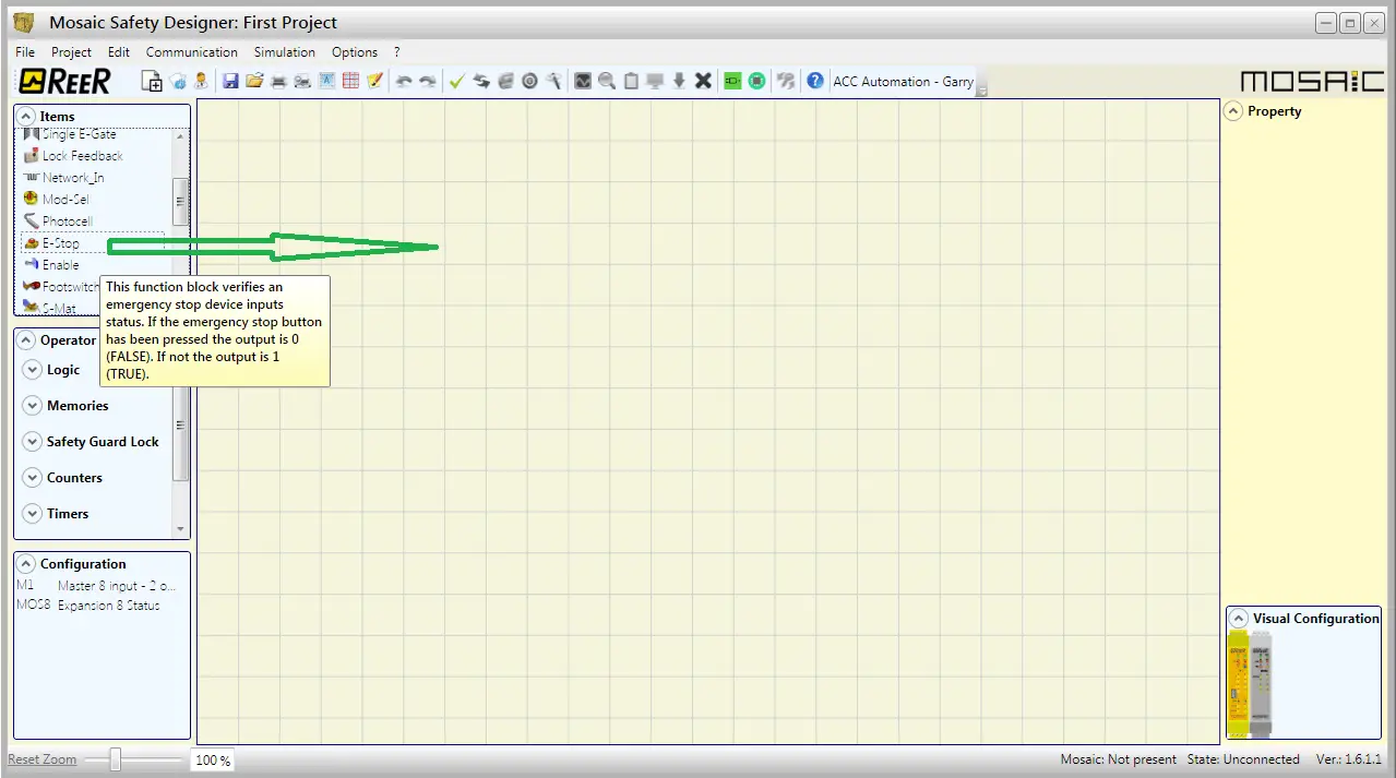
Click and hold the E-Stop input and drag this onto the work area of the project. You will see as the mouse hovers over the items in the list description is displayed for your reference.
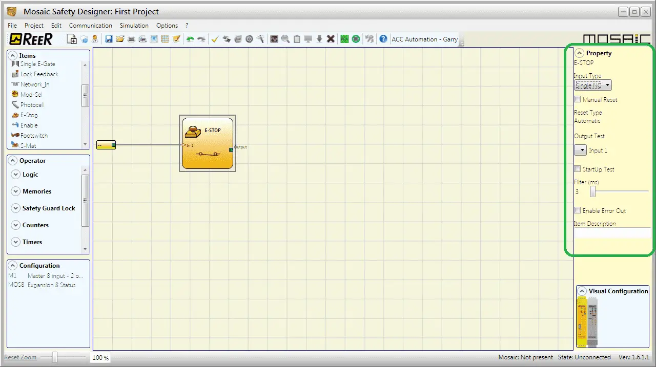
The E-Stop input is not placed on the work area. Since the E-Stop button is highlighted, you will notice that the property window is populated with the features that can be set with this input. The Item Description can be used to write text above our input for documentation purposes. This is an important part of the program.
We will leave all of the properties in their default state.
Click the input tag.
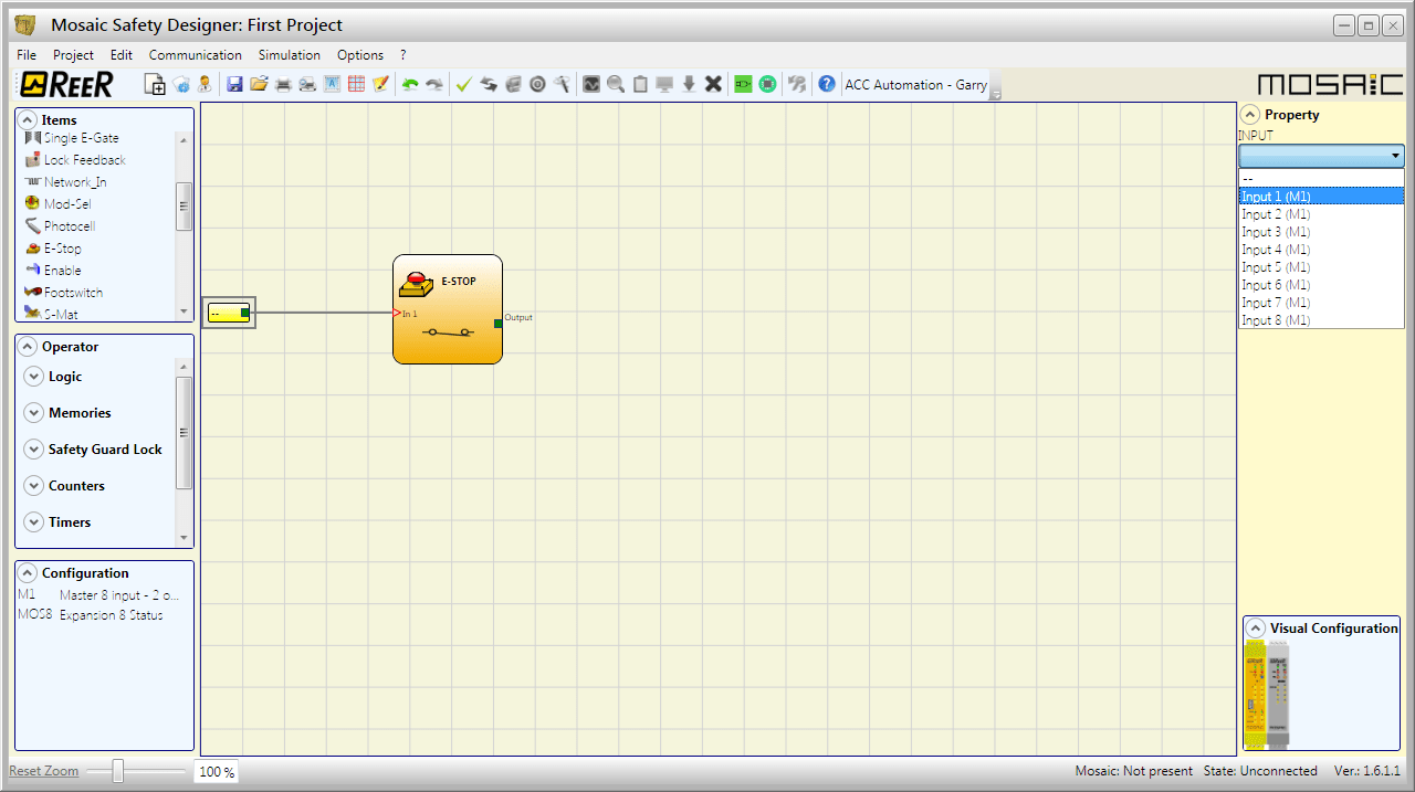
Our property window will now display all of the INPUT tags available from our configuration. We will choose Input 1 (M1) as the INPUT.
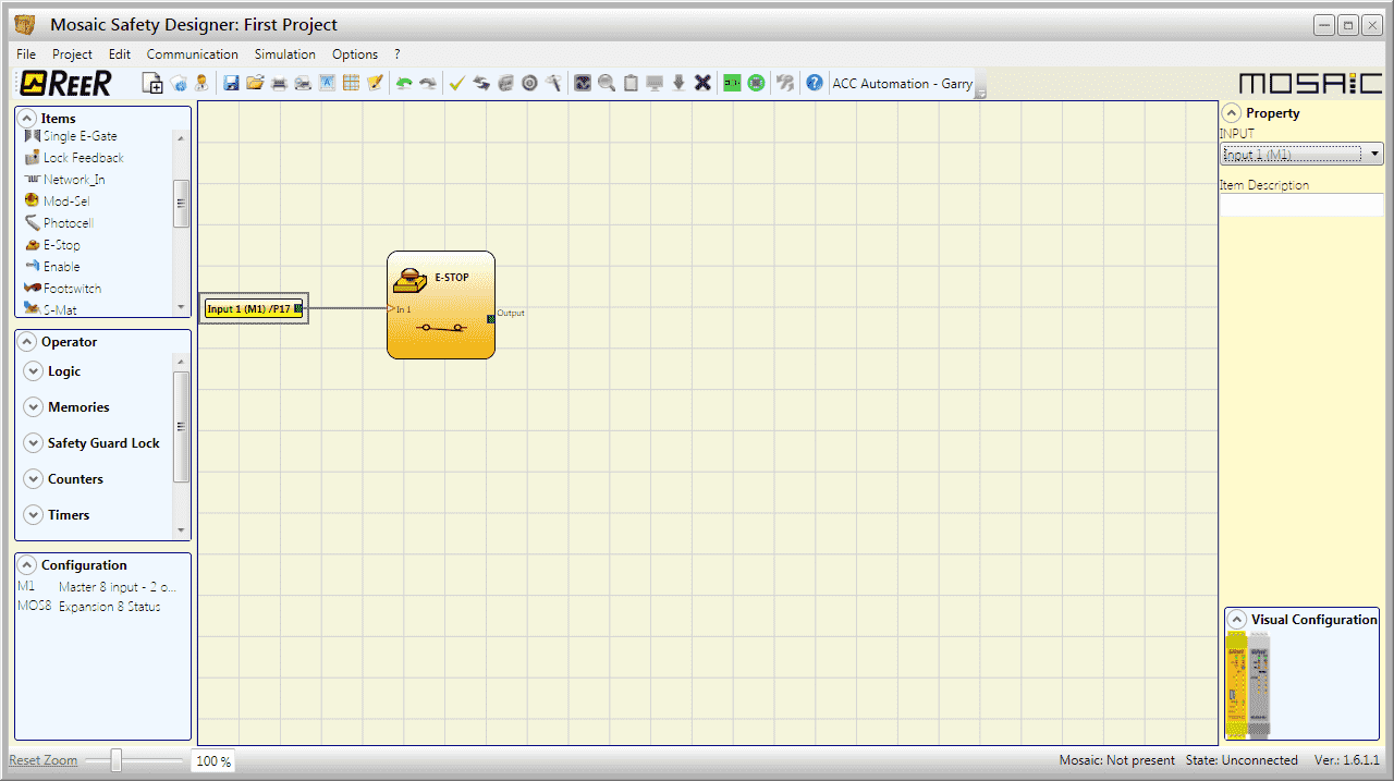
Once again we can add an Item Description for the input tag. The tag itself is labeled “Input 1(M1) / P17” This means that pin 17 on our MOSAIC M1 controller will be the input for our E-Stop button.
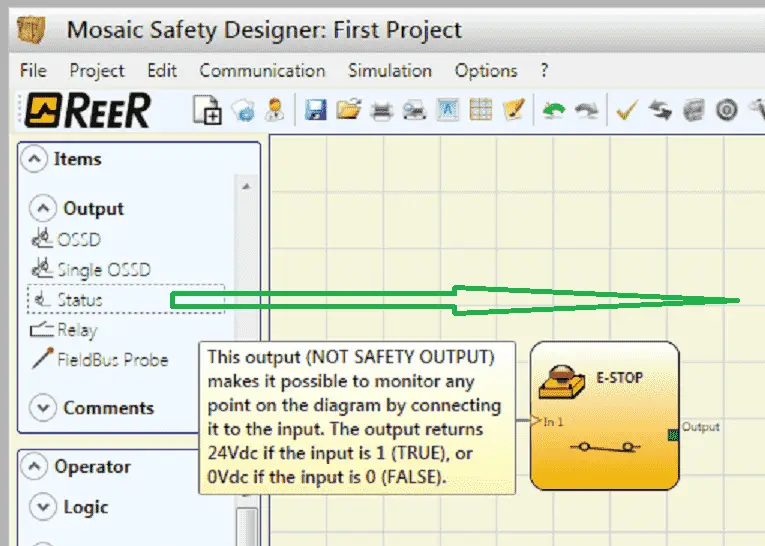
Choose Status from the Output items under the Items window. Click and drag the Status output onto the work area.

We can position the Status output anywhere in the work area. We can add a text label to this element under the property window on the top right. (Item Description)
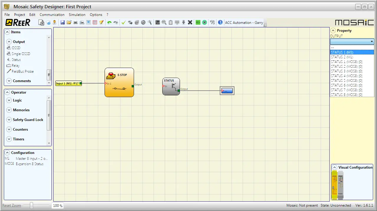
Click on the Status output tag. Our property window will now display all of the OUTPUT tags available from our configuration. We will choose STATUS 1 (M1) as the OUTPUT.
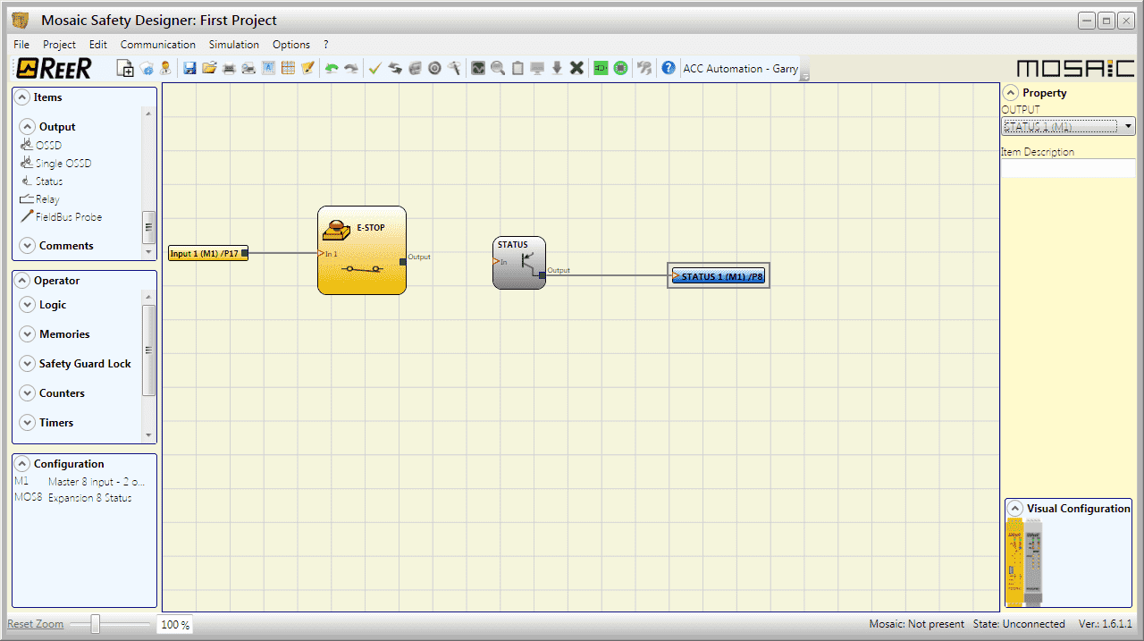
Once again we can add an Item Description for the output tag. The tag itself is labeled “Status 1(M1) / P8” This means that pin 8 on our MOSAIC M1 controller will be the output for our STATUS item.
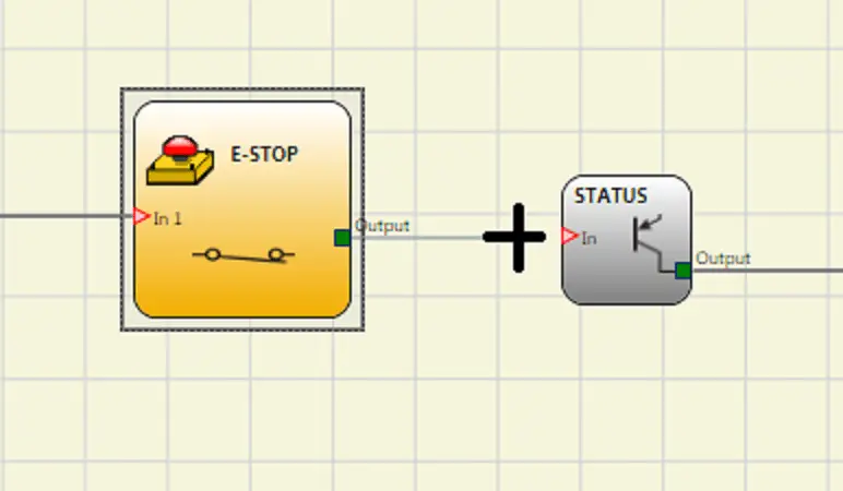
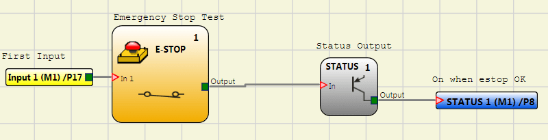
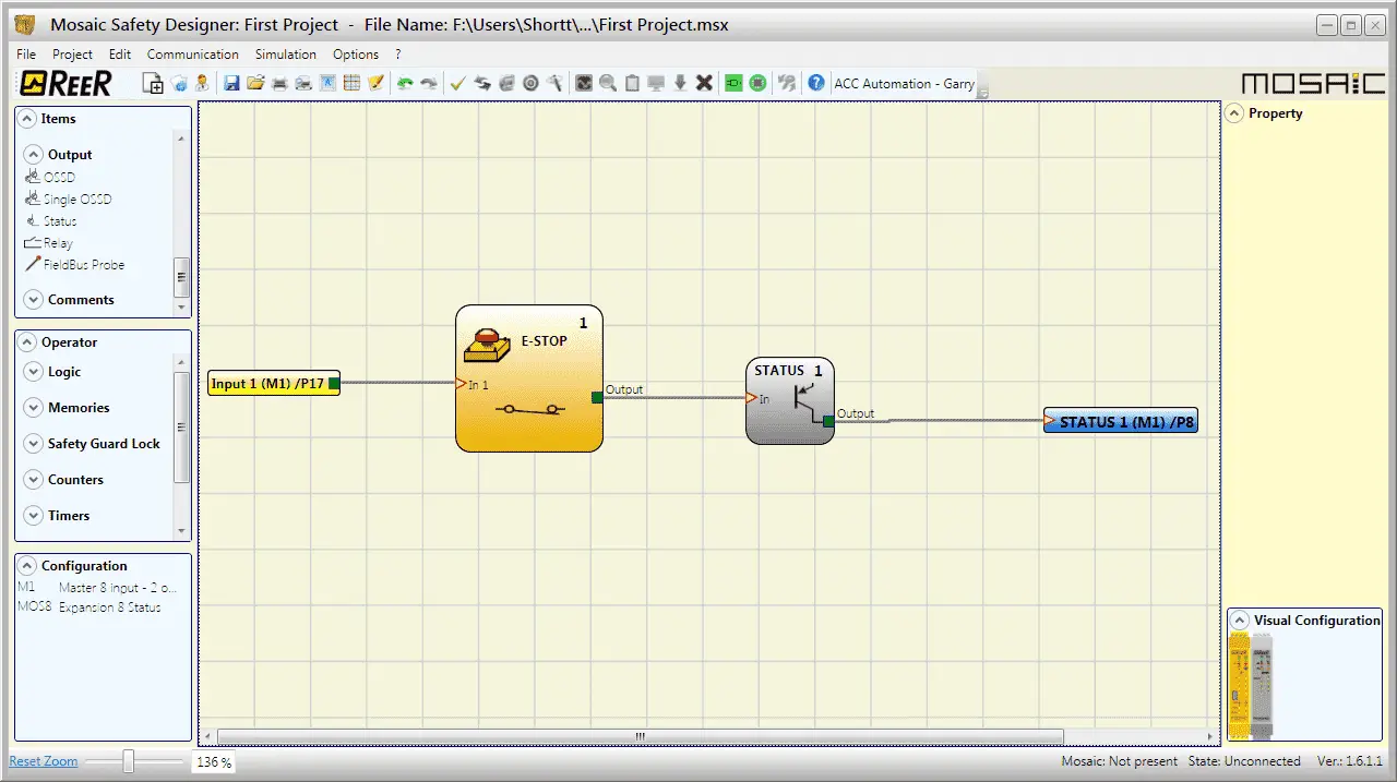
We can now join our E-Stop output to our STATUS input. Position your mouse over the E-Stop output. Left click and hold while you drag a line over to the STATUS input. Release the left mouse key and your connection will be made. (Line was drawn)
Watch the video below to see the programming of our MOSAIC Safety Controller using the MSD software.
Saving Your Project – MOSAIC Safety Controller
Select Save under the File option in the main menu.
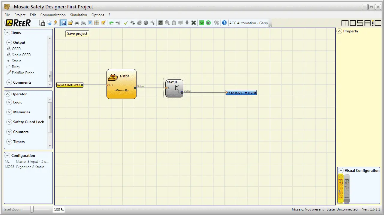
Alternatively, you can click the Save Project icon on the main screen.
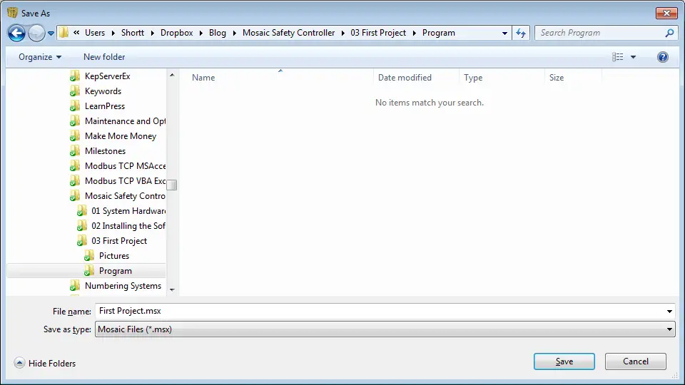
The name will be “First Project”. This is the same name we gave it under the project information. All Mosaic Files will be stored with a file extension of .msx. Select Save.
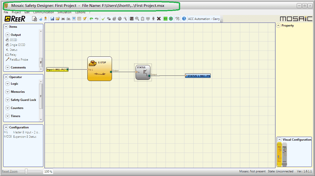
Our complete file extension will be displayed at the top of the main screen.
Project Validation – MOSAIC Safety Controller Program
The project validation will ensure that all of the items programmed have tag assignments and the physical logic is valid.
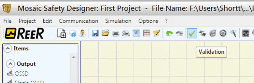
Select the Validation (Check Mark) icon on the main menu.
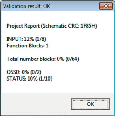
Here are the results of our validation. The top of the window will read Validation result: OK. This will also tell us other statistics about our project. Hit OK to close the window.
Schematic Simulation – MOSAIC Safety Controller Program
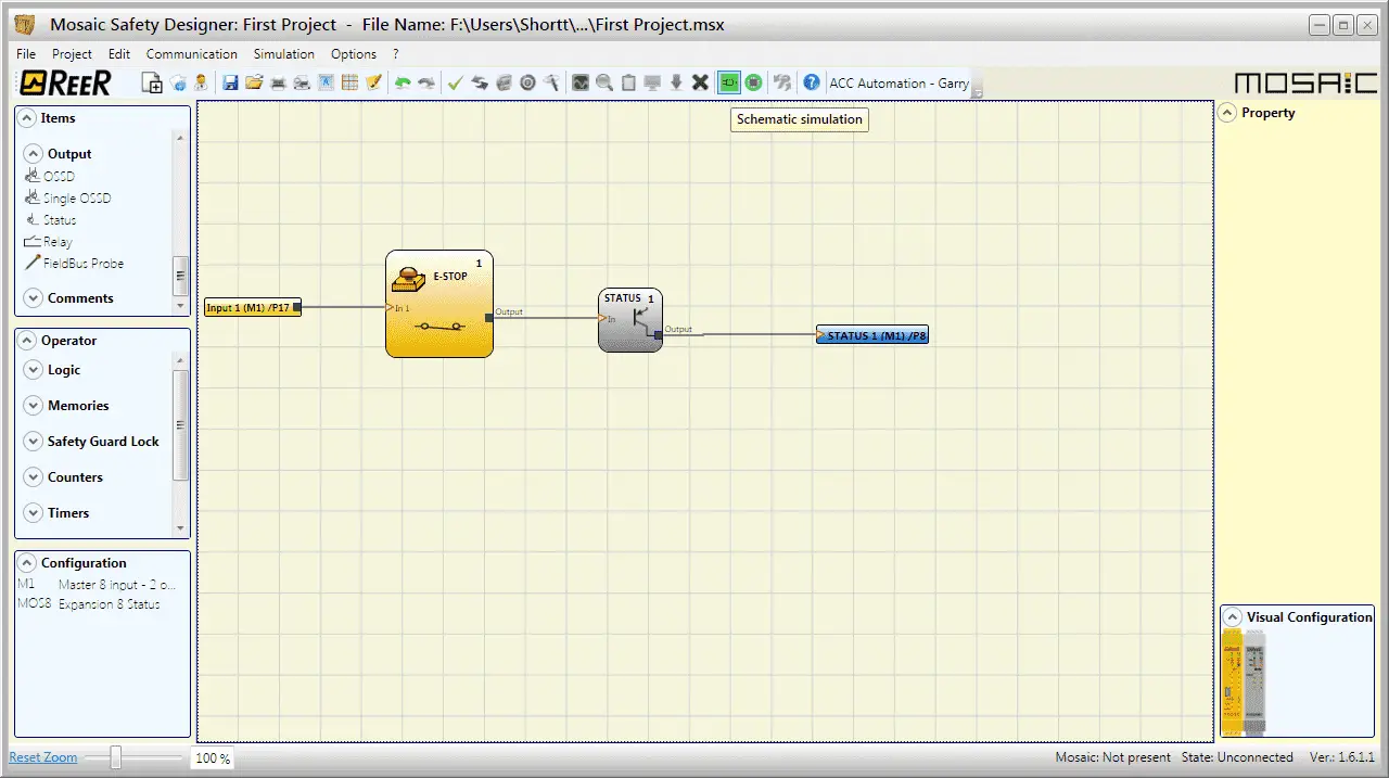
Schematic simulation can be used to check/guide the output signals of the various functional blocks in real-time, even during the actual simulation. You may choose the block outputs you wish to control and check the response of the various elements of the schematic model. Select the schematic simulation icon on the main screen to start the simulation.
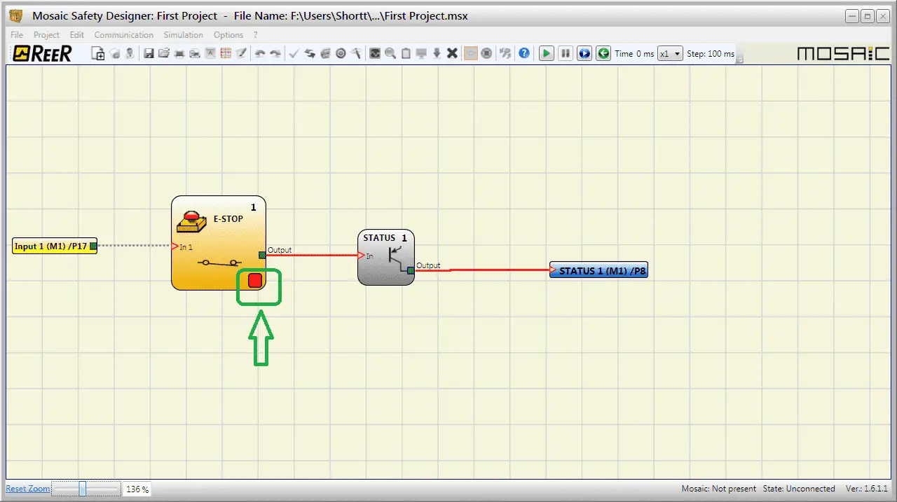
Our simulation is now operating. We can increase the size of the elements by using the zoom function in the bottom left corner. Our current percentage is 136.
Notice that the lines connecting our E-Stop input to our Status input are red. The Status output to the output tag is also red. This means that the status output is off. We can now use our mouse to click on the red square on our E-Stop input.
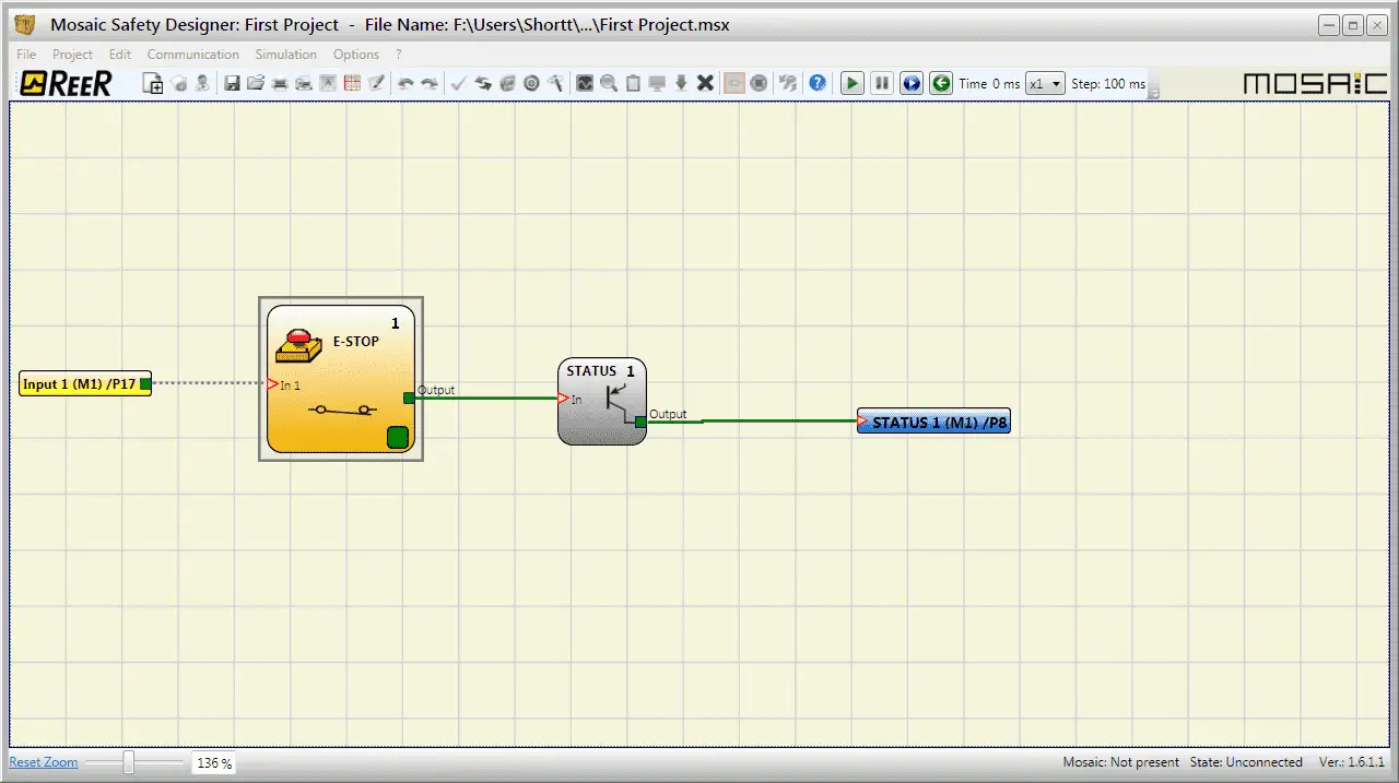
Our E-Stop input is now being made. The output is green to the Status input and the Status output is green (on) to the output tag.
You can see that we can easily test our logic of the controller before downloading it into the actual controller.
Clicking the Schematic simulation icon again will stop our simulation.
Note: This simulator is only designed to assist in the design of safety functions. The results of the simulation do not constitute a validation of the project. The resulting safety function must always be validated, from the point of view of both hardware and software, under actual usage conditions in accordance with the applicable regulations, such as ISO/EN 13849-2: validation or IEC/EN 62061: Chapter 8 – Validation of the safety-related electrical control system.
Mosaic configuration safety parameters are provided in the MSD software report.
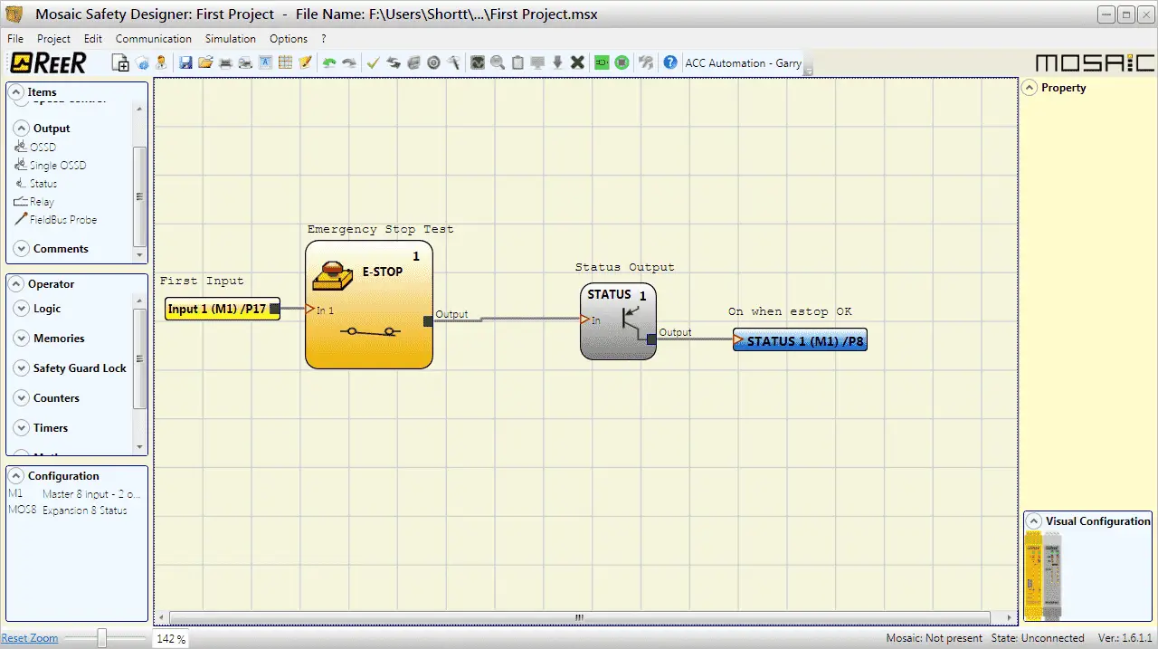
Here is our program complete with Item Descriptions.
Download our first MOSAIC project program here.
Watch the video below to see the verification and simulation of our first program on the MOSAIC Safety Controller.
ReeR MOSAIC Safety Controller (Automation Direct) Advantages:
- Reduces the number of devices and wiring used and overall size of the project
- Speeding-up control panel construction
- Allows tamper-proof system configurations
- All logic is configured through a graphic interface
(no more laborious wiring is needed as with traditional solutions) - The lower number of electromechanical components also means a better performance level and a higher safety level
- The project report provides the actual values of PFH, DCavg, and MTTFd according to EN 13849-1 and EN 62061
ReeR MOSAIC Safety Controller
MOSAIC Controller Installation and Use Manual
MOSAIC Field bus Modules: Installation and Use
Supplemental Communication information and example wiring diagrams
Product Datasheets (Installation and Setup Instruction)
MSD – MOSAIC Safety Designer Software – (Free Download Link) – The software will contain all of the instruction sets and help files for the MOSAIC Safety Controller.
Next time we will continue programming our first project on our MOSAIC Safety Controller. (Part 2)
Watch on YouTube: MOSAIC Safety Controller First Program Part 1
If you have any questions or need further information please contact me.
Thank you,
Garry
If you’re like most of my readers, you’re committed to learning about technology. Numbering systems used in PLC’s are not difficult to learn and understand. We will walk through the numbering systems used in PLCs. This includes Bits, Decimal, Hexadecimal, ASCII and Floating Point.
To get this free article, subscribe to my free email newsletter.
Use the information to inform other people how numbering systems work. Sign up now.

The ‘Robust Data Logging for Free’ eBook is also available as a free download. The link is included when you subscribe to ACC Automation.