The C-More HMI Panel software uses virtual components called Objects. These objects are programmable to simulate the functions that you require on your automation project. Pushbuttons, Switches, meters, and graphs are just a few of the objects that are available to you.
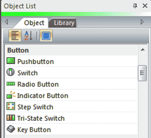
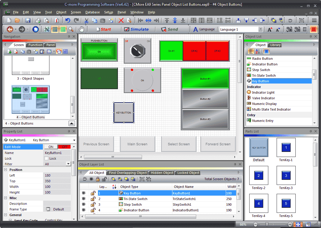
Continuing from last time we will now look at the object buttons that we can use with our HMI panel. The button objects that are available on the C-More EA9 are Pushbuttons, Switches, Radio Buttons, Indicator Buttons, Step Switches, Tri-State Switches, and Key Buttons. Let’s get started.
Previously in this C-More EA9 HMI Panel series, we have done the following:
System Hardware
– Unboxing and Review Video
– Powering the Unit Video
Installing the Software – Video
System Setup Screens – Video
First Program
– Establishing Communication and Updating Firmware Video
– First Program Video
Panel to PLC and PLC to Panel Settings – Video
Common Screen Menu – Video
Simulate Project – Video
Object List Shapes – Video
Watch the video below to see the Object Buttons in action on our C-More EA9 HMI Panel.
Setting Our C-More Object Button Page
We will be adding to the program we created last time. (C-More EA9 HMI Series Panel Object List Shapes).
Select new screen under the main menu | Screen | New Screen…
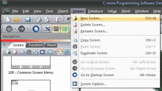
Alternatively, we can also use the icons in the Navigation panel.
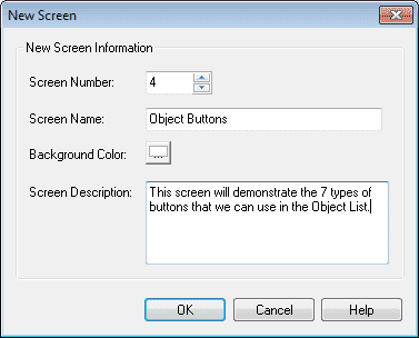
We will name screen 4 Object Buttons. The screen description can be used to describe the screen. Hit OK.
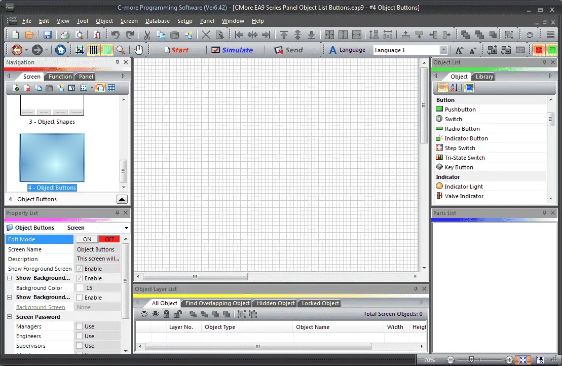
Our new screen will now be displayed.
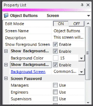
Under the property, list window turn on the editing and enable the show background. Select Common Screen Menu under the background screen. Turn off the edit mode under the property list.
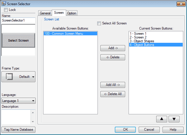
We must now add our new screen so we can select it when using the common screen menu. Select page 100. Select the Screen Selector button. Under the Screen tab, select the 4 – Object Buttons and hit the Add button so it moves it over to the Current Screen Buttons. Hit OK. We can now go back to our newly created Object Buttons screen page 4 from our navigation window.
Our new screen is now ready for us to add buttons.
C-More Tag Name Database
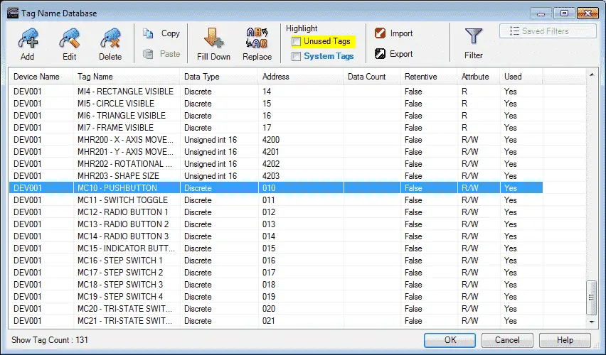
We will use the following addresses to control the button objects on the cmore HMI.
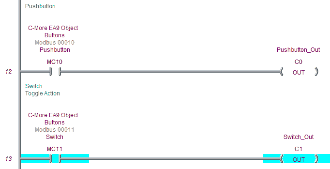
MC10 – Discrete On/Off – Modbus Address 00010 – Read / Write (Pushbutton)
MC11 – Discrete On/Off – Modbus Address 00011 – Read / Write (Switch Toggle)
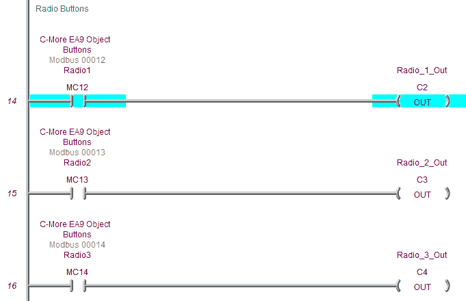
MC12 – Discrete On/Off – Modbus Address 00012 – Read / Write (Radio 1)
MC13 – Discrete On/Off – Modbus Address 00013 – Read / Write (Radio 2)
MC14 – Discrete On/Off – Modbus Address 00014 – Read / Write (Radio 3)
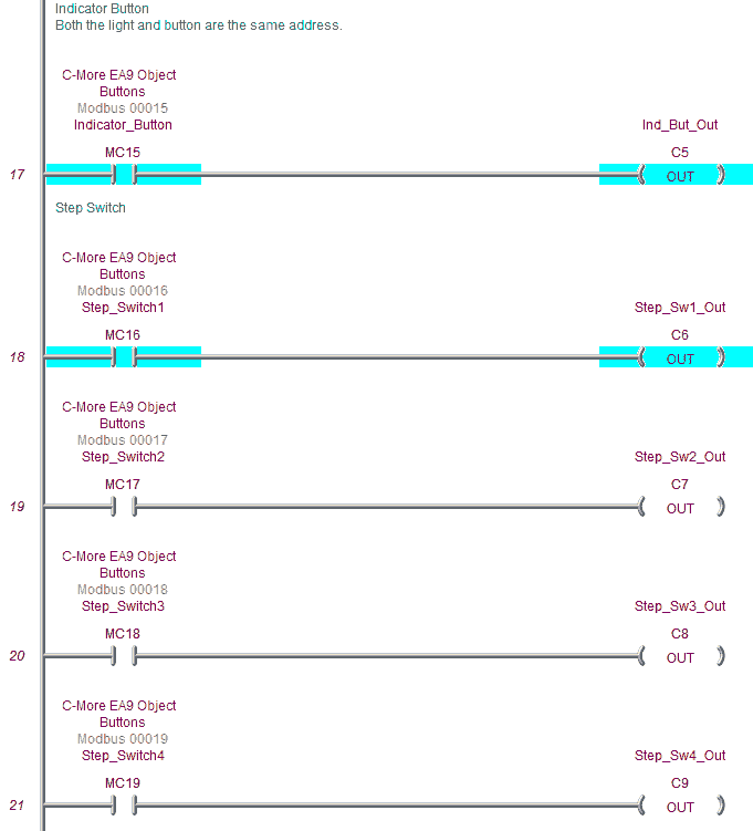
MC15 – Discrete On/Off – Modbus Address 00015 – Read / Write (Indicator Button)
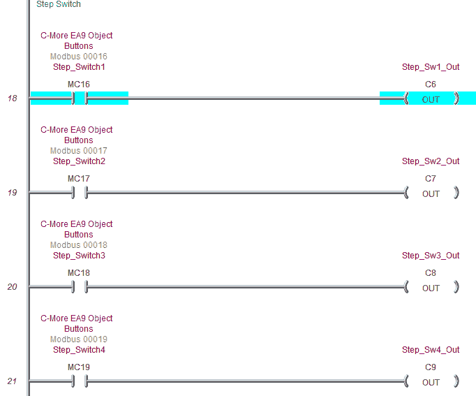
MC16 – Discrete On/Off – Modbus Address 00016 – Read / Write (Step Switch)
MC17 – Discrete On/Off – Modbus Address 00017 – Read / Write (Step Switch)
MC18 – Discrete On/Off – Modbus Address 00018 – Read / Write (Step Switch)
MC19 – Discrete On/Off – Modbus Address 00019 – Read / Write (Step Switch)
MC20 – Discrete On/Off – Modbus Address 00020 – Read / Write (Tri-State)
MC21 – Discrete On/Off – Modbus Address 00021 – Read / Write (Tri-State)
C-More Button Objects
Button objects refer to single bits in the PLC. We can control these discrete tags by using a button object to turn them on (1) or off (0).
Pushbutton
The pushbutton object is an electronic version of a typical pushbutton normally found on control panels. This pushbutton object can be assigned a tag name and used to activate or deactivate bits in the PLC.
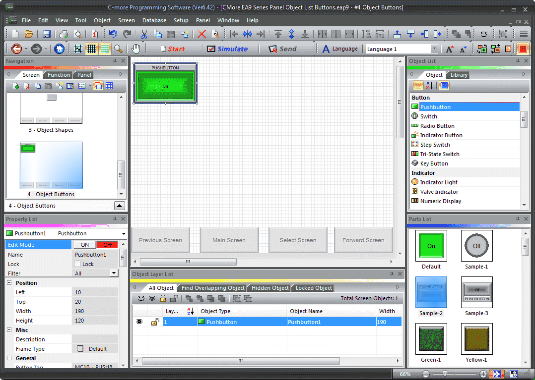
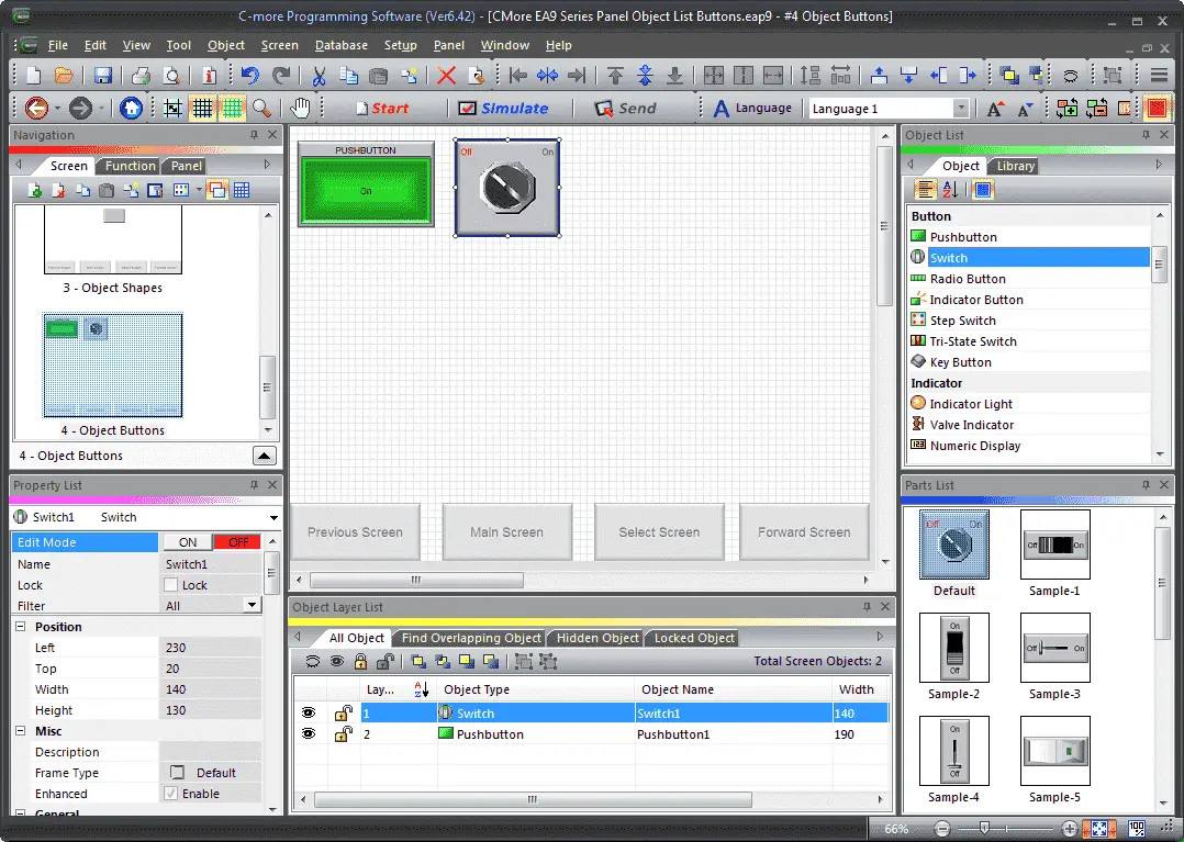
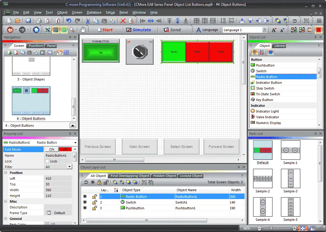
Select Screen 4 from the navigation window. We will now add a Pushbutton under the Object list window. Left click (hold) and drag the Sample-2 under the Parts List for the Pushbutton onto the screen.
Note: Choose a preconfigured part from the Parts List window for the object selected. This will save time when configuring objects. Click and drag the item from the parts list to the screen. All of the objects will have a parts list.
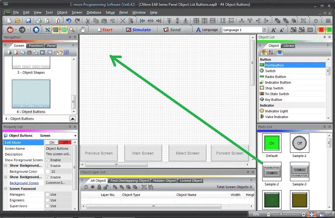
The Pushbutton screen window will display. You can also use the main menu | Object | Button | Pushbutton… and click on the work area of the screen. This will give you the default pushbutton selection.
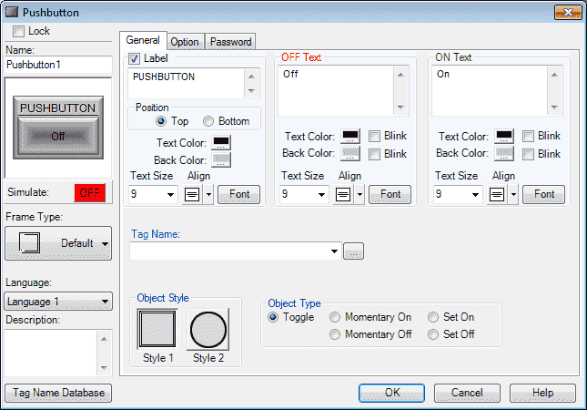
The following parameters can be set:
Name: This is the name of the object. The default is Pushbutton1
Object Preview Window: This will show what the object will look like on the screen.
Simulate: This is used to test the function of the pushbutton object. Click the ON or OFF box to simulate.
Frame Type: The pushbutton object can be displayed in a series of frames. We will leave this as the default value.
Language: We will leave this as our default Language 1.
Description: We can enter up to 400 words to describe the purpose of the pushbutton that we are programming.
Tag Name Database: This will open a window that allows you to add, edit or delete tag names.
General Tab
Label: This will add a label to the pushbutton. We will select this and leave the default name of PUSHBUTTON in the label text field. The position of the label will be Top and we will leave the default colour, alignment, and font.
OFF Text: This will allow us the change the text that will appear on the pushbutton when the object is off. We will leave the default values for the text, colour, background colour, alignment, and font.
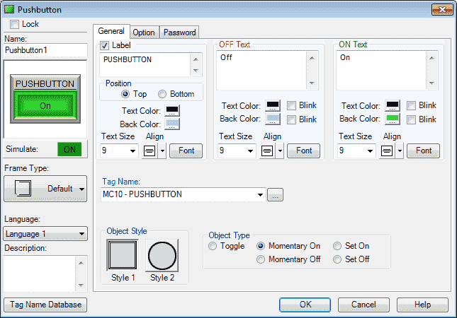
ON Text: This will allow us the change the text that will appear on the pushbutton when the object is on. We will leave the default values for the text, colour, alignment, and font. Change the background colour to green so we can visibly see when this turns on.
Tag Name: This is the tag name of the bit that we will be controlling with the pushbutton. The right button next to the drop-down menu will open a window that allows you to add, edit or delete tag names. Select MC10 (Modbus Address 00010)
Note: Only the tags that can be used with the pushbutton are displayed.
Object Style: You can select your preferred style. We will leave this as the default of Style 1.
Object Type: This allows us to choose between five types of operation for the pushbutton object. We will leave this as the default of toggle.
– Toggle: The toggle will alternate between ON and OFF every time the pushbutton is pressed.
– Momentary On: The pushbutton will be on when the pushbutton is being pressed. As soon as the button is released it turns to the OFF state.
– Momentary Off: The pushbutton will be off when the pushbutton is being pressed. As soon as the button is released it turns to the ON state.
– Set On: The state of the pushbutton will be ON when pressed. It will remain ON until a separate device like another pushbutton or signal from the PLC turns it OFF.
– Set Off: The state of the pushbutton will be OFF when pressed. It will remain OFF until a separate device like another pushbutton or signal from the PLC turns it ON.
Option Tab
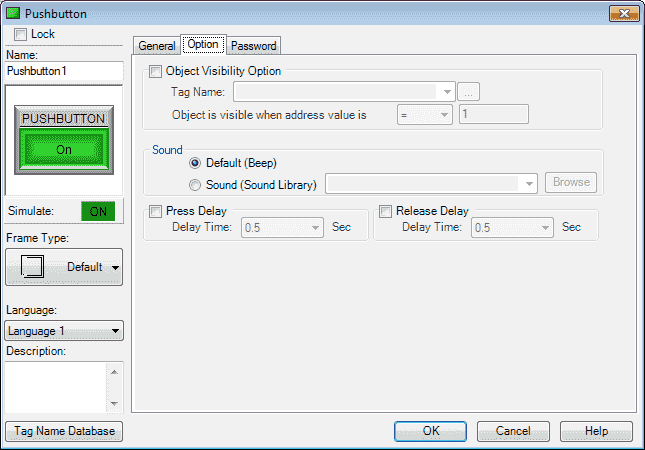
Object Visibility Option: We can use this selection to configure a tag to control when the object appears on the screen. C-More EA9 HMI Series Panel Object List Shapes – Video will demonstrate how we use this option.
Password Tab
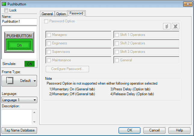
Password options can be set up for this object. Click OK.
Note: Special notes will be on the password window for the object.
We can now position and resize the Pushbutton object on our screen using our mouse.
C-More Switch
The switch object is an electronic version of a typical switch normally found on control panels. This switch object can be assigned a tag name and used to activate or deactivate bits in the PLC. We will now add a switch to our screen.
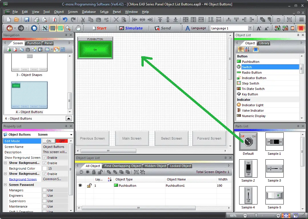
Select switch from the Object List under Button. Now click and hold Default from the parts list and drag onto our screen.
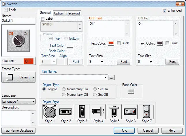
The Switch window now appears. This is similar in a lot of the items that we have already programmed for the pushbutton object above. The object style has many more items to choose from to suit your needs.
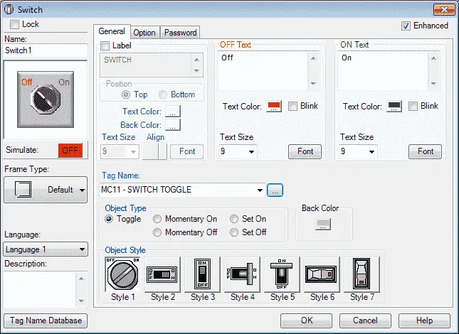
Leave the text, position, colour, background colour, alignment and font as default. Our tag name will be MC11 (Modbus Address 00011). We will also leave the object type as a toggle. This means that as we select this switch on our panel, will turn on and off alternately with each press.
Option Tab
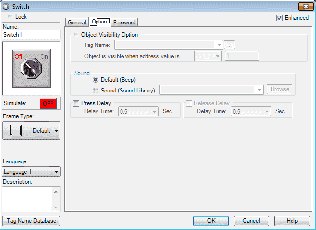
We can select the visibility, sound, and press/release delay.
Password Tab
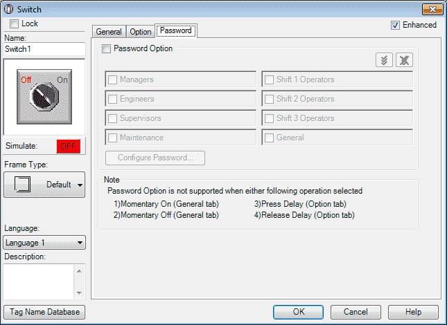
We will not use a password, but it can only be used in the toggle object type.
Select OK.
We can now use the mouse and size and move our switch object.
C-More Radio Button
The radio button object has 2 to 8 buttons. Only one button can be selected at any time.
We will now add a radio button to our screen.
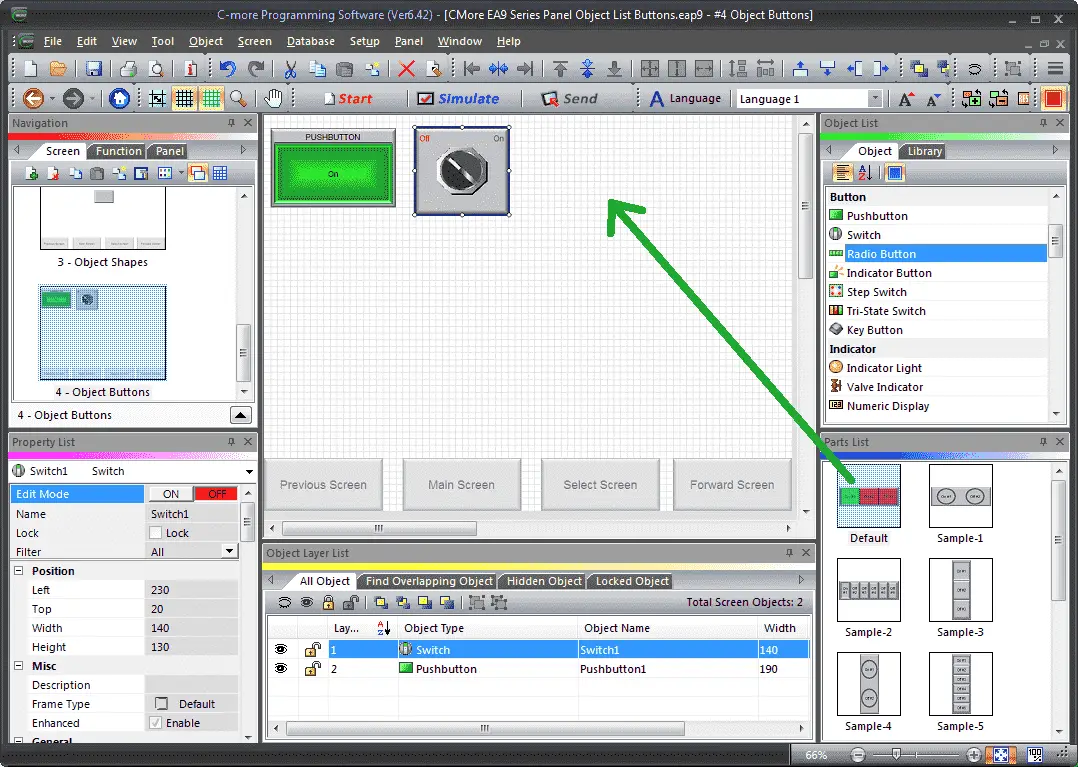
Select radio button from the Object List under Button. Now click and hold Default from the parts list and drag onto our screen.
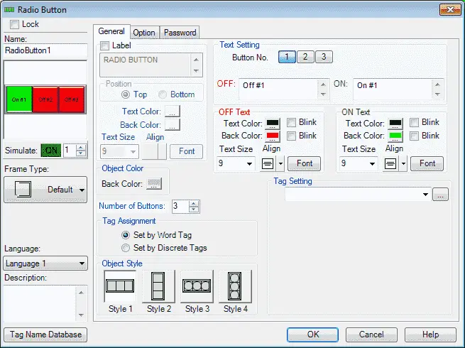
The radio button window will now appear. These object windows will all have a similar look and feel.
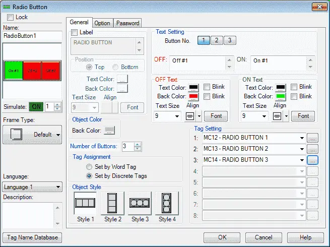
We will set the Number of Buttons to 3. The tag assignment will be set by discrete tags. If we set the word tag, the bits in the word will be activated when the radio buttons are pressed. Here are our tag settings:
1: MHR12 (Modbus Address 00012)
2: MHR13 (Modbus Address 00013)
3: MHR14 (Modbus Address 00014)
Option Tab
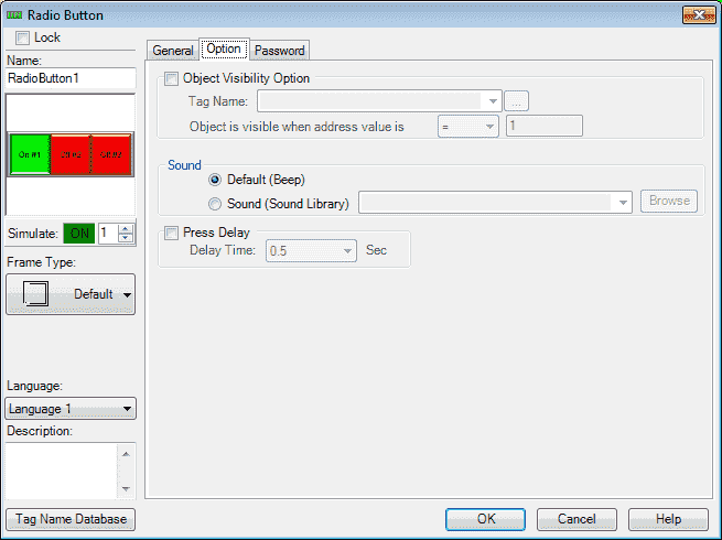
We can select the visibility, sound, and press/release delay.
Password Tab
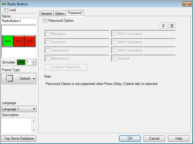
We will not use a password, but it is not supported when the press delay under the option tab is selected.
Select OK.
We can now use the mouse and size and move our radio button object.
C-More Indicator Button
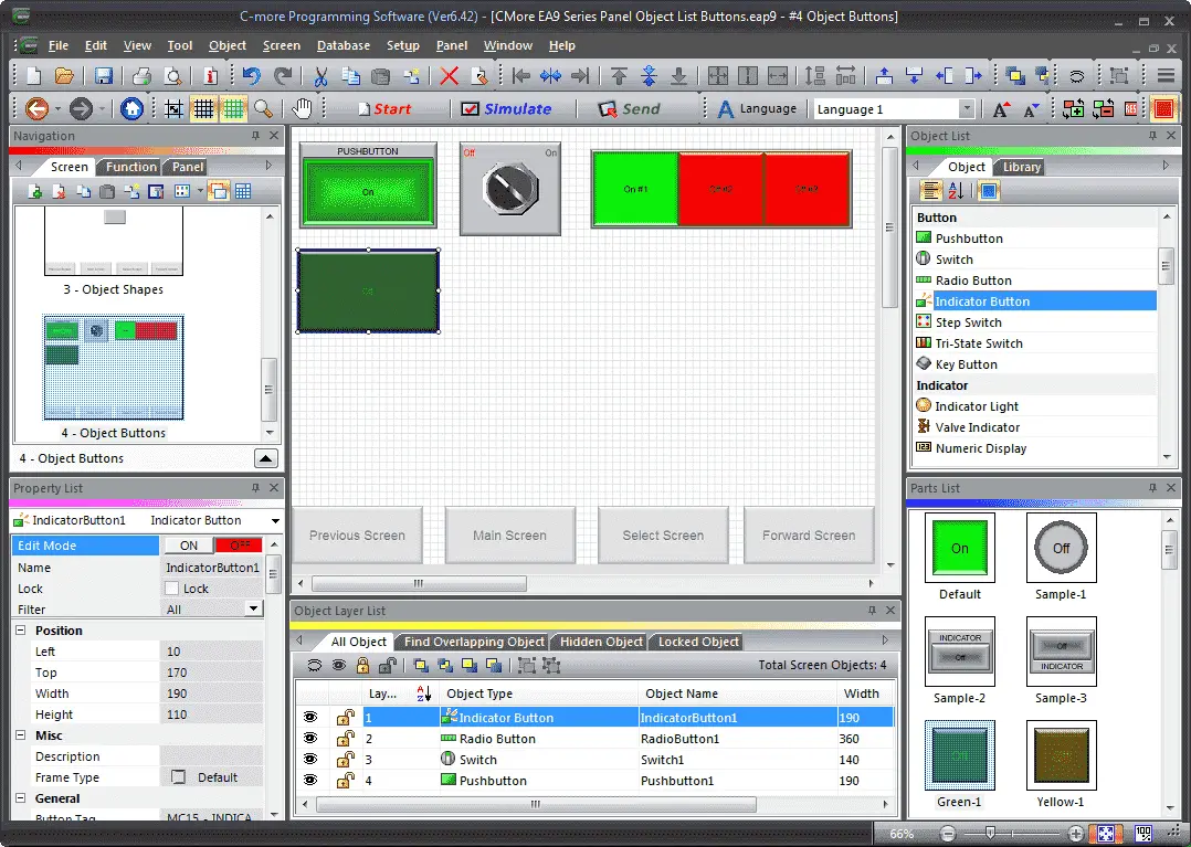
The indicator button is a combination of a pushbutton and an indicator light. We can assign two different tags for each of the functions of this object. Let’s add our indicator button to our screen.
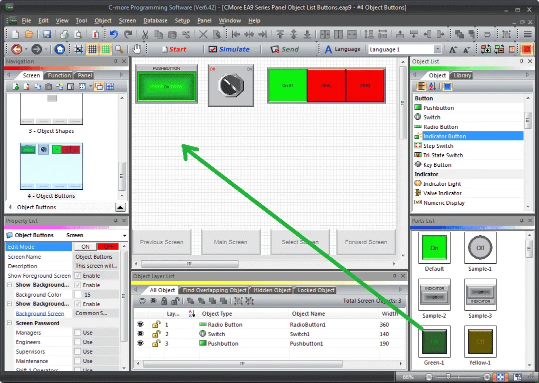
Select indicator button from the Object List under Button. Now click and hold Green-1 from the parts list and drag onto our screen.
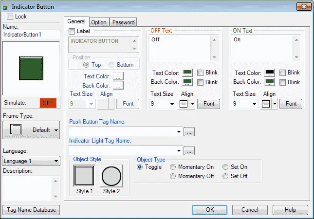
The indicator button window will now appear.

We will set the Push Button Tag Name to MC15. (Modbus Address 00015) The Indicator Light Tag Name will be MC15 as well. (Modbus Address 10015) All of the other parameters we will leave as their default.
Option Tab
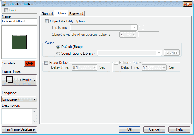
We can select the visibility, sound, and press/release delay.
Password Tab
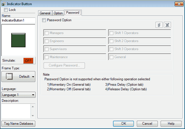
We will not use a password, but it can only be used in the toggle object type.
Select OK.
We can now use the mouse and size and move our indicator button object.
C-More Step Switch
The step switch will mimic an actual mechanical step switch that when pressed will turn on in sequence the outputs.
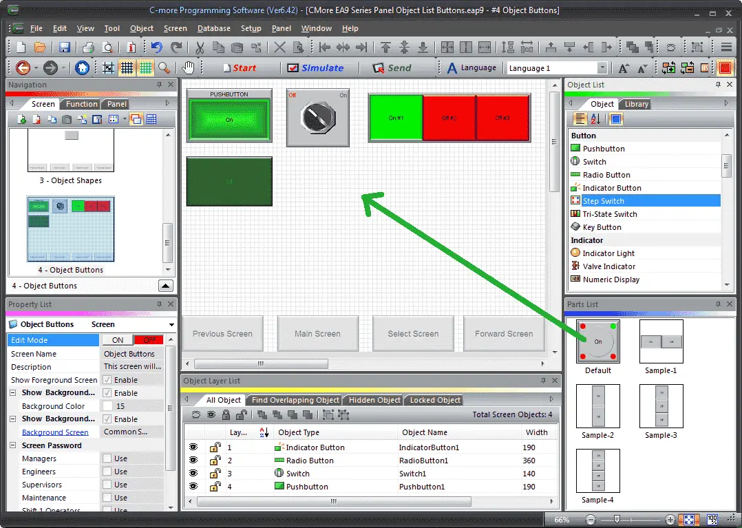
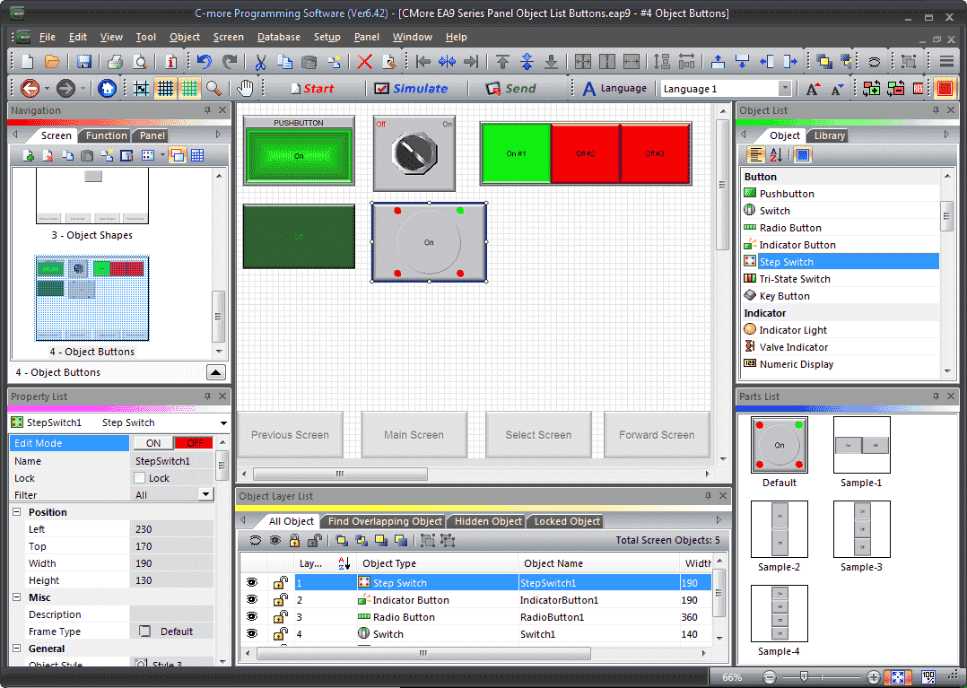
Select Step Switch from the Object List under Button. Now click and hold Default from the parts list and drag onto our screen.
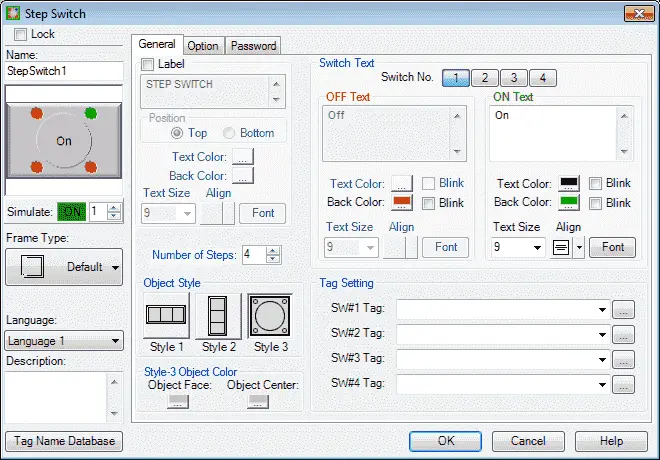
The step switch window will now appear.
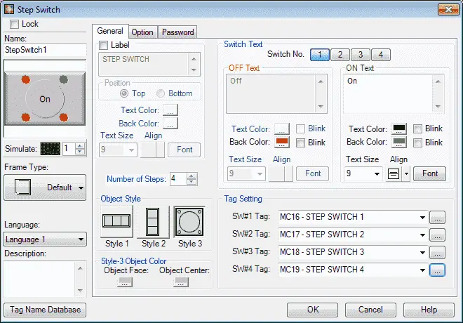
We will set the Tag Settings to the following:
SW#1 Tag: MC16. (Modbus Address 00016)
SW#2 Tag: MC17. (Modbus Address 00017)
SW#3 Tag: MC18. (Modbus Address 00018)
SW#4 Tag: MC19. (Modbus Address 00019)
All of the other parameters we will leave as their default.
Option Tab
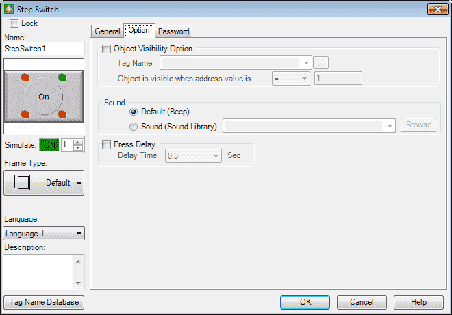
We can select the visibility, sound, and press/release delay.
Password Tab
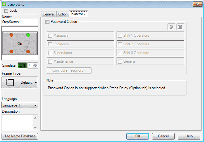
We will not use a password, but it can not be used when press delay is selected on the option tab.
Select OK.
We can now use the mouse and size and move our indicator button object.
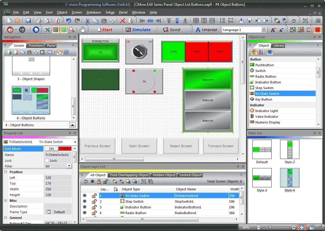
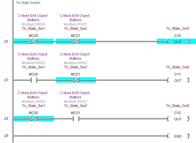
C-More Tri-State Switch
The Tri-State Switch Object is a set of three pushbuttons where the left button is a Reset that turns off both other buttons. We will add a tri-state switch to our screen.
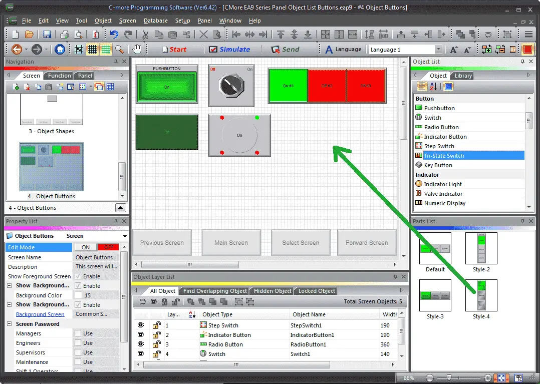
Select Tri-State Switch from the Object List under Button. Now click and hold Style-4 from the parts list and drag onto our screen.
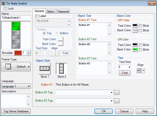
The tri-state switch window will now appear.
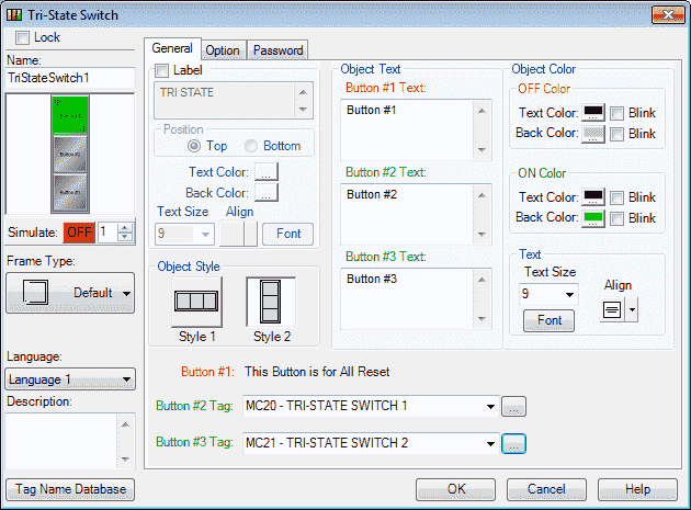
We will use MC20 (Modbus Address 00020) for Button #2 Tag and MC21 (Modbus Address 00021) for Button #3 Tag. All of the other parameters will be left as their default values.
Note: Button #1 is used to turn off both the other buttons.
Option Tab
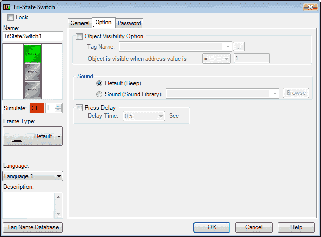
We can select the visibility, sound, and press/release delay.
Password Tab
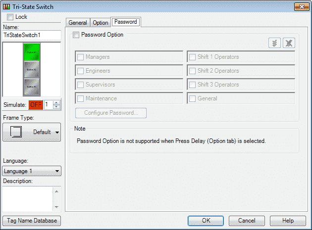
We will not use a password, but it can not be used when press delay is selected on the option tab.
Select OK.
We can now use the mouse and size and move our tri-state switch object.
C-More Key Button
The Key Button object is a button mainly used to create a Define Keypad like the ones available from the Define Keypad selection of the Navigation window. The Key Button Object can be used to input numbers or text on Objects that require data entry.
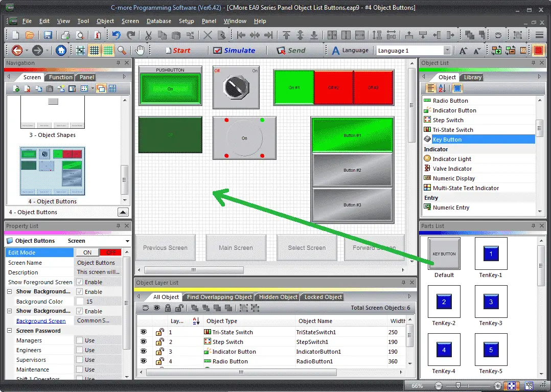
Select Key Button from the Object List under Button. Now click and hold Default from the parts list and drag onto our screen.
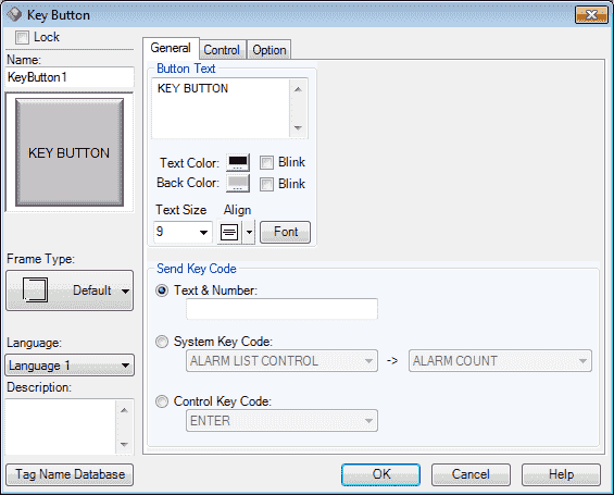
The key button window will now appear.
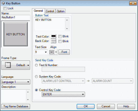
We will select the Control Key Code and then select ENTER.
Note: Our demonstration will only show the select of the key button and not how to define a keypad.
Control Tab
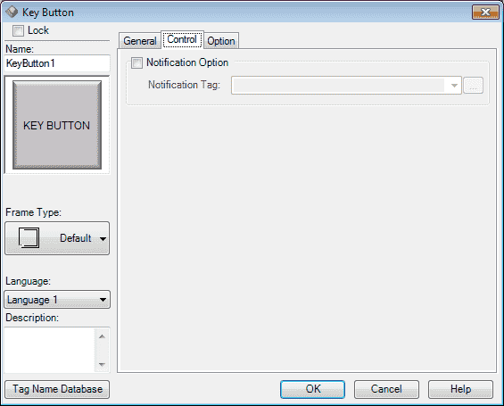
We can set a notification tag that will turn on when this key is pressed.
Option Tab
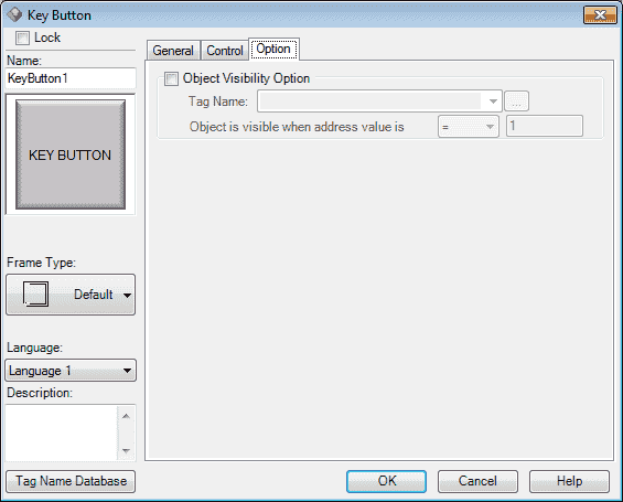
We can select the visibility of the key.
Select OK.
We can now use the mouse and size and move our key button object.
Define Keypad
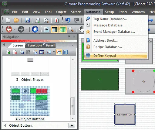
In the main menu | Database | Define Keypad we can show the keypads that have been programmed in our project.
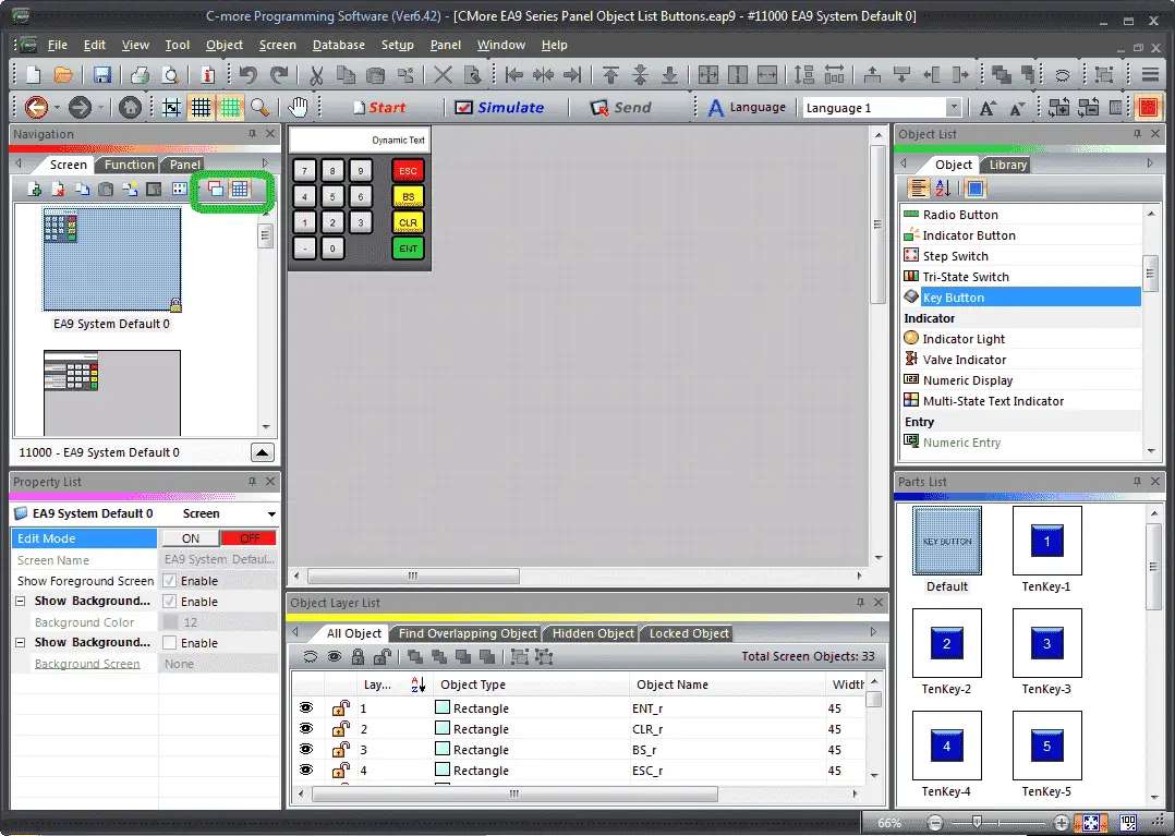
You can also use the icons in the Navigation Panel to call up the keypads. Adding a customized keypad can be done here.
Click the screen icon to return to the screens.
Watch the video below to see the Object Buttons in action on our C-More EA9 HMI Panel.
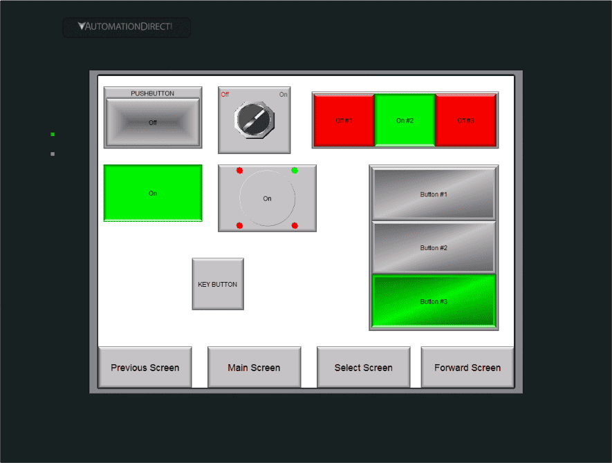
Simulate our C-More EA9 Object Buttons Project
We can use the simulator to view and try our object buttons. This will ensure the visual and bit operation that we want in our program.
C-More Object Buttons PLC Program Additions
Using the program we previously developed, we will add additional rungs to control the button objects that we have just created.
Download the PLC and C-More program here.
Watch the video below to see the Object Buttons in action on our C-More EA9 HMI Panel. This will also demonstrate the PLC ladder code for functionality.
C-More EA9 Panels from Automation Direct
https://www.automationdirect.com/c-more/home
C-More – Graphic Panel (EA9 Series) User Manual and Quick Start Guides
https://cdn.automationdirect.com/static/manuals/ea9userm/ea9userm.html
EA9-T10CL C-More Specifications
https://cdn.automationdirect.com/static/specs/ea9t10cl.pdf
C-More EA9 Programming Software (Current Version V6.42)
https://support.automationdirect.com/products/cmore.html
This software will enable you to program all of the C-More EA9 HMI units. It includes a simulator for your application.
Next time we will look more at the object list indicators that we can use in the C-More HMI Panel.
Watch on YouTube: C-More EA9 HMI Series Panel Object List Buttons
If you have any questions or need further information please contact me.
Thank you,
Garry
If you’re like most of my readers, you’re committed to learning about technology. Numbering systems used in PLC’s are not difficult to learn and understand. We will walk through the numbering systems used in PLCs. This includes Bits, Decimal, Hexadecimal, ASCII and Floating Point.
To get this free article, subscribe to my free email newsletter.
Use the information to inform other people how numbering systems work. Sign up now.

The ‘Robust Data Logging for Free’ eBook is also available as a free download. The link is included when you subscribe to ACC Automation.