Node-RED Modbus TCP can recover from communication errors automatically. Options are available to you the programmer to continue the Node-RED flow upon detection of these errors.
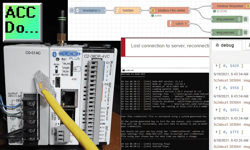
Broken Ethernet cable, Modbus Server power, and Node-RED Client offline are just a few of the errors that can occur on the industrial plant floor. Our Node-RED program must account for and be tested for each of these conditions.
We will be communicating Modbus TCP (Ethernet) to our Click Plus PLC. Using the catch node we will detect and display errors that may occur. Let’s get started.
In this series we used Node-RED in some of the following ways:
Installing the Windows Software – Video
Modbus Communication – Video
User Interface – Dashboards – Video
SQL Database Log – Video
SQL Database Spreadsheet Connection – Video
Install Node-RED on Raspberry Pi – Video
Do-More PLC Node-RED HTTP Request – Video
Simple Click Data Logging – Video
Node-RED Windows Startup
Node-RED will be running on a Windows 10 64-Bit computer. Open up a command prompt window and enter “node-red” at the prompt.
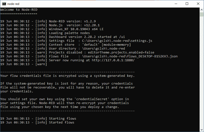
This will now run our Node-RED program. To install Node-RED see the following post.
Node-RED Modbus TCP Communication Program
Our Node-RED Modbus TCP communication sample program will poll our Modbus Server every 100 milliseconds. (10 times per second) The first two Modbus holding registers will be read. These read memory addresses will be displayed using the Modbus Response node and the Debug node. The Catch node is used to capture when an error occurs and then display on the Debug node.

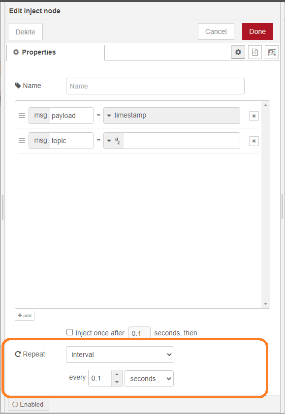
The inject node will be set up for a repeat interval of 0.1 seconds. (100ms)
A function node is used to set up the Modbus communication.
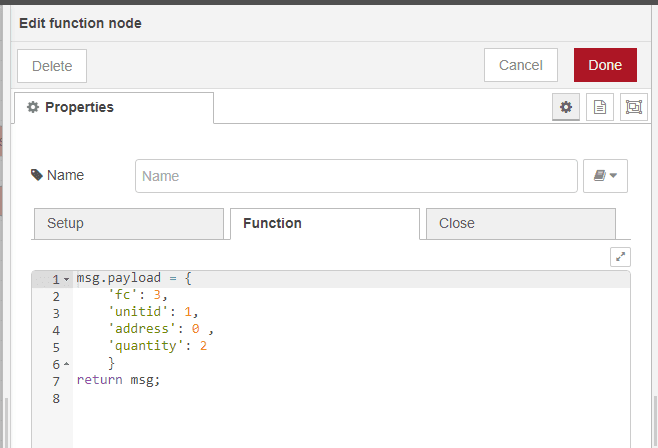
Function code 3 is used for reading contents on a contiguous block of holding registers in a remote device.
Unit ID is set for 1. This will determine what Modbus server we wish to establish communication with.
Address 0 will be the starting address. Modbus addressing can sometimes be confusing. 5 and 6 digits addressing are used. The leading digit refers to the type of register being read.
Example: 400000 / 40000 – means holding register 0.
Quantity 2 means that we are reading two consecutive addresses.
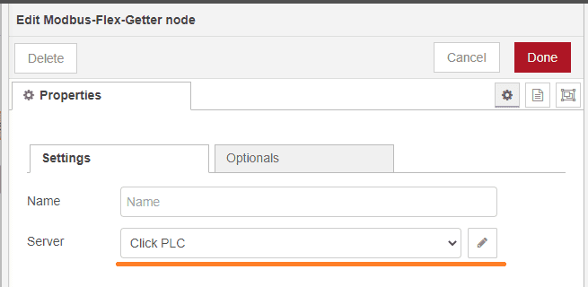
The Modbus-Flex-Getter node will specify the Modbus Server. In our case, this will be the Click PLC. To set the server select the icon next to the Server name.
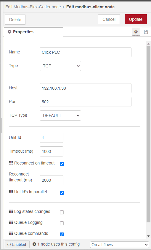
Here are the Modbus server settings for the Click PLC. The default port of 502 is used for Modbus TCP. Timeouts for the server are set for the default of 1 second and 2 seconds for the reconnect. Select update to update any changed parameters.
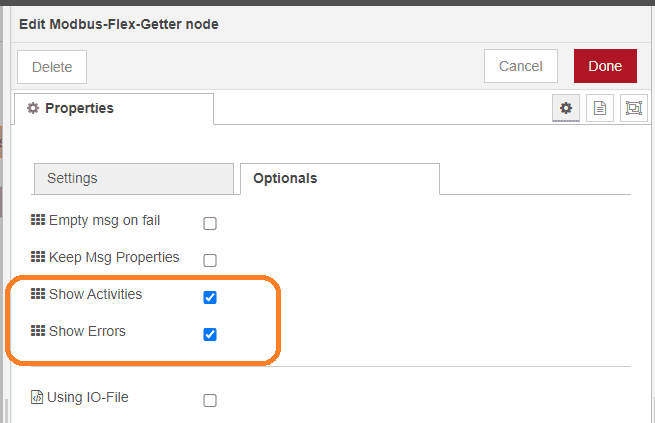
Select show errors and activities under the Optionals tab of the Modbus Flex Getter node. The errors will be used to trigger the Catch node.
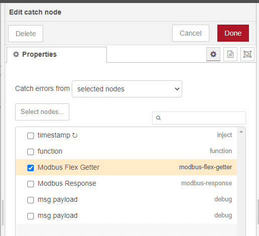
If a node notifies the runtime of an error then the Catch node can be used to create a flow to handle it. Select the Modbus Flex Getter as the node we want to monitor for errors.
Save and deploy our Node-RED program.
Watch the video below to see an explanation of the Node-RED program.
Click Plus Modbus TCP Server Program
The Click Plus PLC will be used as our Modbus TCP Server. We will use a self-resetting timer to give us a value in one of the registers we are reading from Node-RED.
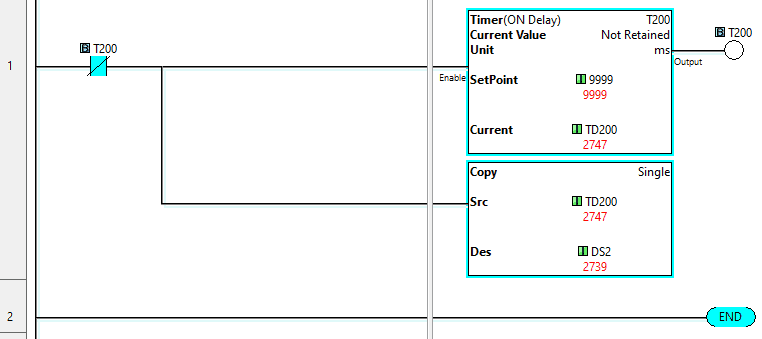
Modbus addresses in the Click PLC can be displayed using the address picker.
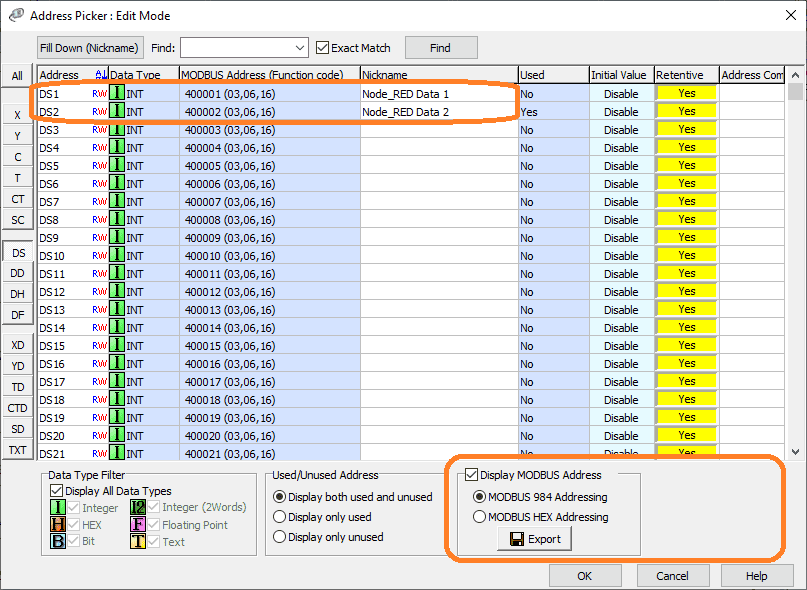
Select Display MODBUS Address in the lower right-hand corner of the address picker window in the Click programming software.
Additional information on the Click PLC can be obtained in our Click PLC Series. This will take you through all of the features of this low-cost powerful controller.
Node-RED Modbus TCP Testing Errors
Monitoring the Debug tab we can see that the Modbus addresses are being displayed correctly.
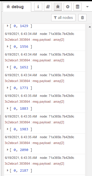
If we were to disconnect the Ethernet cable or power down the Click PLC Modbus Server, the catch node will pick up the error and display it.
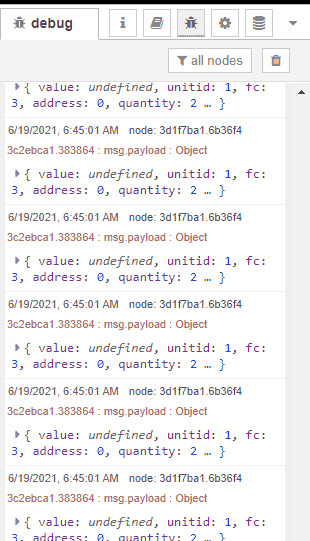
Plugging the cable back in or powering up the Modbus Server will automatically resume operation.
Stop Node-RED from running on the computer by entering Ctrl+X.
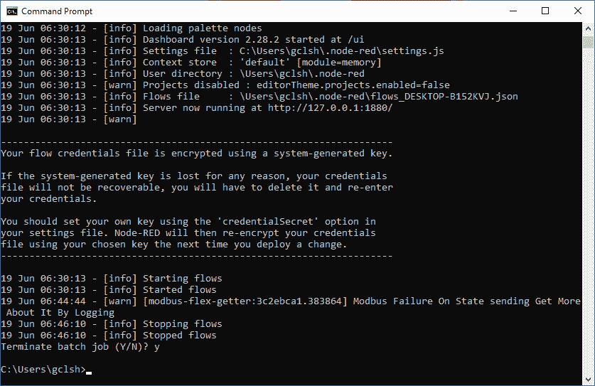
Our browser will now display the lost connection to the server message.

Starting Node-RED will automatically remove the error message and continue running our Node-RED program.
Watch the video below to see the communication error handling of Modbus TCP using Node-RED.
Download the Node-RED, and PLC programs here.
Node-RED Links
Node-RED Organization Home Page
Getting Started – Run Locally
Node-RED running on Windows (Run at Startup)
Securing Node-RED
Node-RED Essentials Videos (Basics of the Editor)
Learn JavaScript Free
w3schools JavaScript Tutorial
learn-js.org
Node-Red JavaScript Primer
Modbus
Node-RED Modbus TCP and Serial
Dashboard – HMI
Node-RED Dashboard
Node-RED Dashboard extra nodes
SQL Database
Node-RED SQL Database
Node-RED SQL Plus – Execute queries and stored procedures
Modbus Learning Links:
Simply Modbus Frequently Asked Questions
Modbus TCP/IP Overview – Real-Time Automation
All You Need to Know About Modbus RTU – Video
Watch on YouTube: Node-RED Modbus TCP Handling Errors
If you have any questions or need further information please contact me.
Thank you,
Garry
If you’re like most of my readers, you’re committed to learning about technology. Numbering systems used in PLCs are not difficult to learn and understand. We will walk through the numbering systems used in PLCs. This includes Bits, Decimal, Hexadecimal, ASCII, and Floating Point. To get this free article, subscribe to my free email newsletter.
Use the information to inform other people how numbering systems work. Sign up now. The ‘Robust Data Logging for Free’ eBook is also available as a free download. The link is included when you subscribe to ACC Automation.

