
Node-RED can easily connect to industrial controls using Modbus communication. Modbus is a master-slave type of communication. Masters will always send the commands to read or write to the slaves on the network. The slaves will respond if the communication is directed at them.
We will be installing the node-red-contrib-modbus palette. This will allow us to communicate Modbus serial (RS485) RTU to a Solo process temperature controller. We will then use Modbus Ethernet TCP to communicate to a Click PLC.
Note: When using Modbus TCP (Ethernet) the master is referred to as the Client and the slave is a Server.
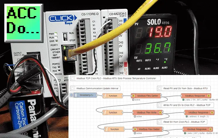
Node-RED will be used to create a single Modbus flow. We will communicate to our Solo process temperature controller using Modbus RTU on a serial RS485 network. The present and set values of the controller will be read. These values will then be written to our Click PLC using an Ethernet Modbus TCP network. A set value from an analog input on the Click will be used to then write to the Solo. This will happen every 200 milliseconds or 5 times per second.
Let’s get started using Node-RED for Modbus communication.
In this series we started using Node-RED in some of the following ways:
Installing the Windows Software – Video
We will continue with the following:
Connect to our industrial equipment using the Modbus protocol.
Display Information on a user interface, HMI, or dashboard
Log information into a database
View information in the database through spreadsheets such as Excel.
Previously we installed Node-RED on our windows 10 computer. I would recommend that you review the following Node-RED Essentials Videos (Basics of the Editor) before continuing. This will allow you to become familiar with the editor.
Installing node-red-contrib-modbus Palette
Node-RED Modbus Nodes
At the command prompt type node-red. This will start the program.
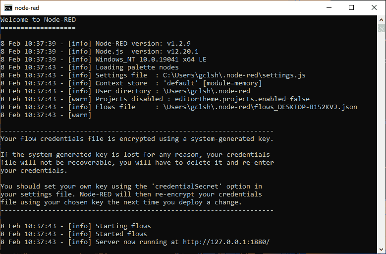
The editor is browser-based. Open your browser and type http://localhost:1880/
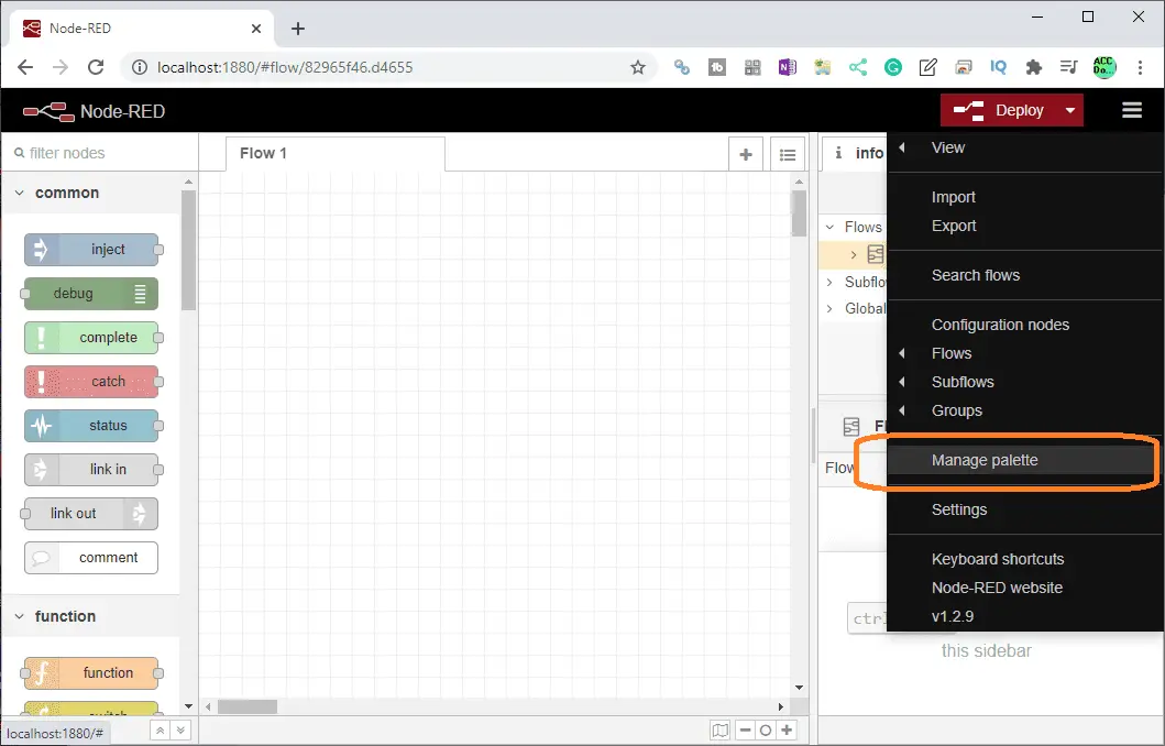
On the right-hand side of the header select the three lines to bring up the menu. Select manage palette.
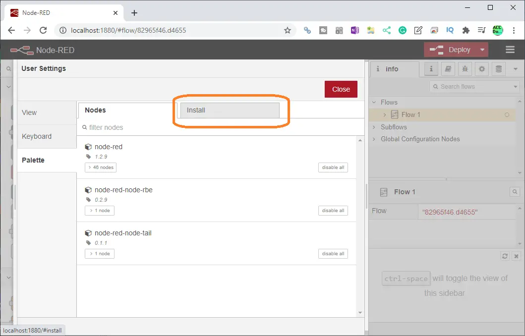
Under the user settings menu, select the palette on the left-hand side. This will show you the current nodes that you have installed. We currently have only the default nodes installed.
Select the install tab.
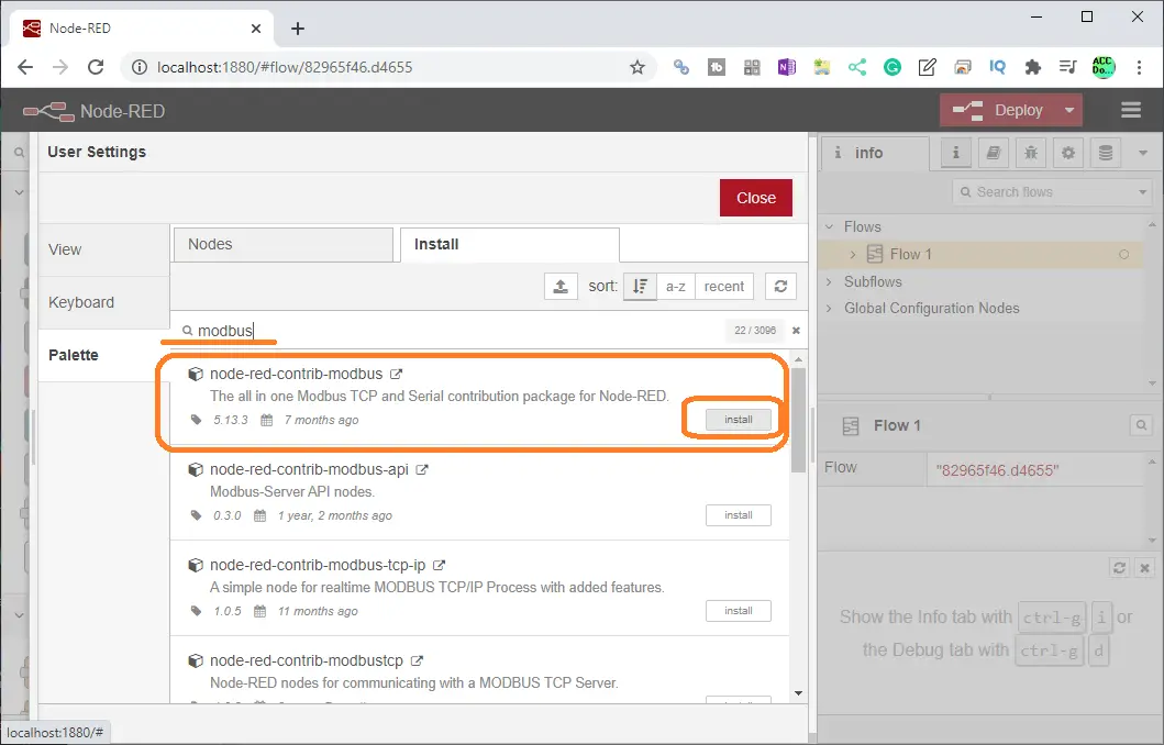
Type in ‘modbus’ in the search field and press enter. Select the install button on the node-red-contrib-modbus palette.
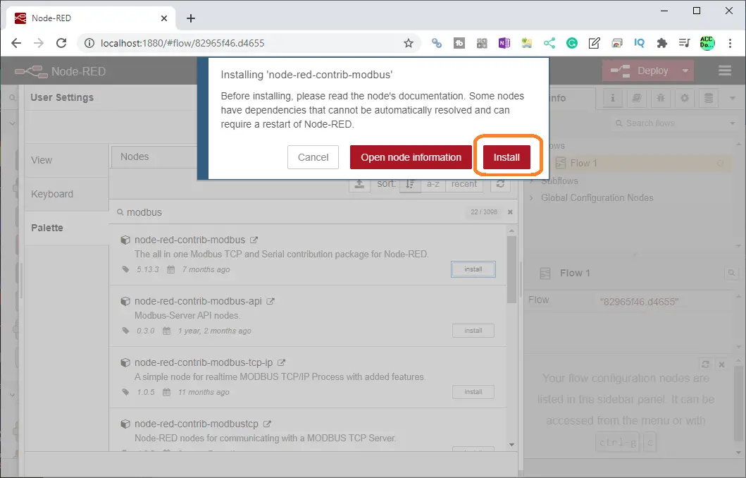
On the pop-up window select install.
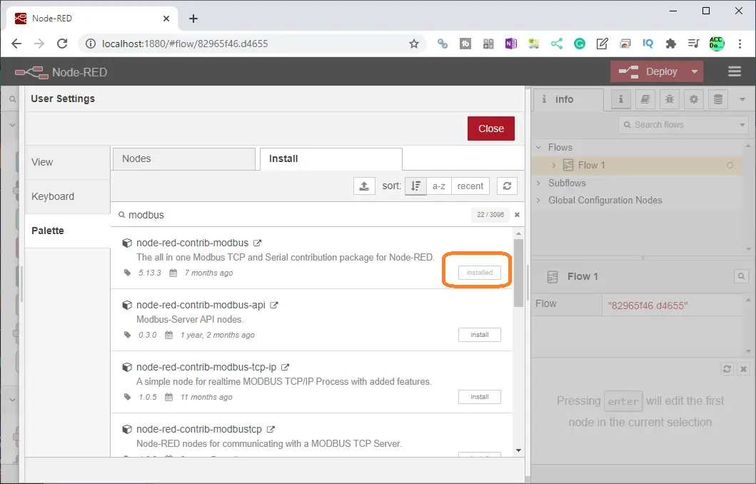
Node-red-contrib-modbus is now installed on your palette. Select the nodes tab.
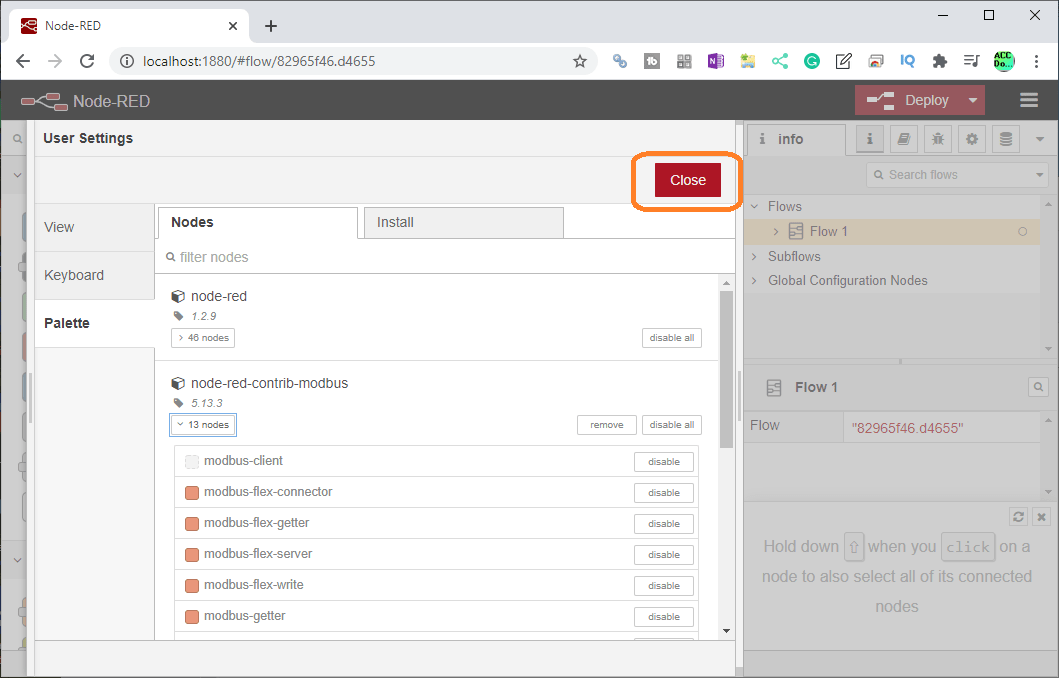
You can now see the 13 nodes installed under node-red-contrib-modbus.
This menu can be used to install and delete node palettes. Select close.
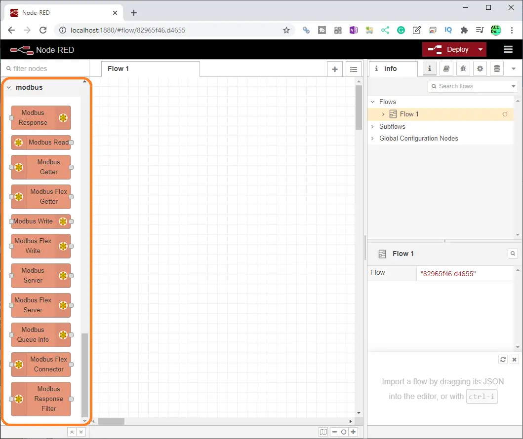
The palette on the editor will now contain the nodes that we will need for Modbus communication. We can now gather and set the information required from the Solo temperature controller and Click PLC needed for Modbus communication.
Solo Process Temperature Controller – Modbus RTU
Solo Settings
The following post will explain how to set up the Solo for Modbus RTU communication and navigate the settings.
SOLO Process Temperature Controller – Video

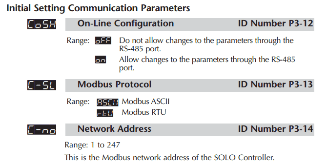
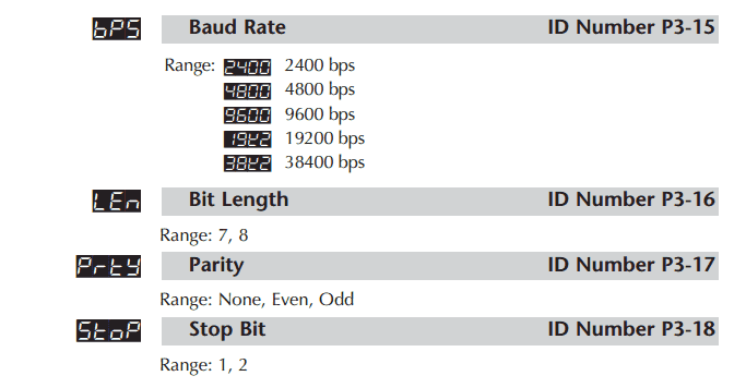
Our example will use the following Modbus RTU settings:
Protocol – Modbus RTU
Baud – 9600
Parity – Even
Data Bits – 8
Stop Bits – 1
Unit Number – 1
Note: We can have 32 different slaves connected to this Modbus network that Node-RED can access. The master (node-red) will use the unit number to specify the information required.
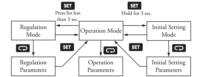
Watch the video below to see the menu navigation and settings on the Solo process temperature controller.
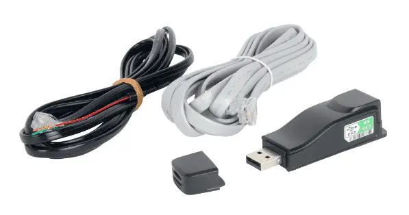
USB to RS485 Converter Settings
The Solo controller uses RS485 serial communication. We will use the USB-485M computer adaptor to connect this serial link network.
USB to RS485 PC Adapter Installation – Video
The above post will show you the installation and monitoring of the communication port in windows device settings.
The settings of the computer com port must match the Solo Process Temperature Controller set above.
Click PLC Modbus TCP Settings
Using the Click programming software, call up the COM Port Setup window. Main menu | Setup | Com Port Setup…
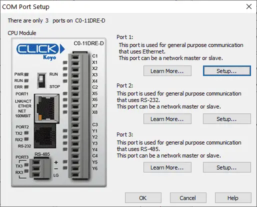
Select Port 1 which is the Ethernet port.
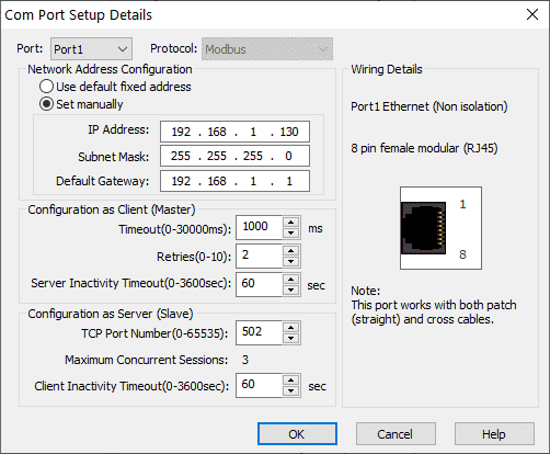
Ensure that you have set up the IP Address, Subnet Mask, and default gateway manually. We will leave the default settings for the configuration as Server (Slave). Select OK.
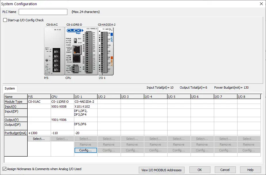
In the system configuration window (Main menu | Setup | System Configuration) we will configure our analog input signal.
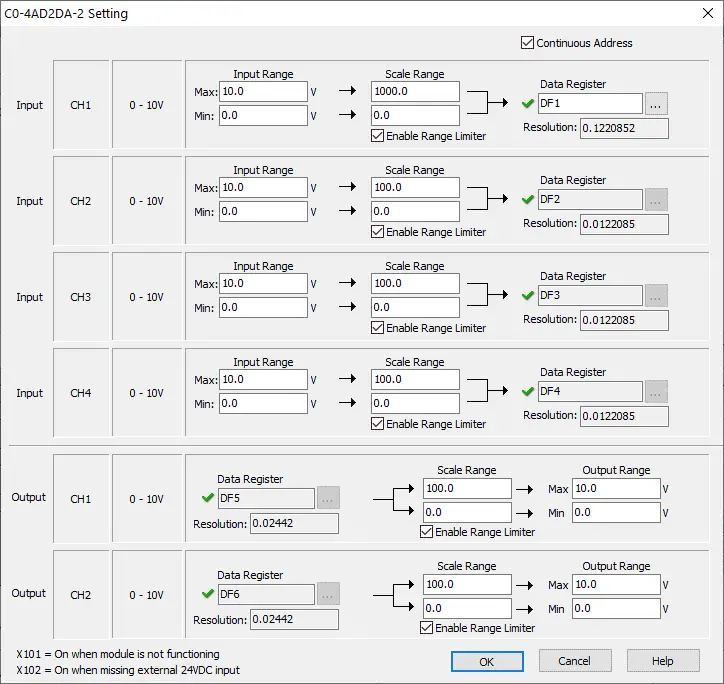
The scaling factor for our analog input will be 0 to 1000. This will represent a value of 000.0 to 099.9 degrees for our Solo set point. Select OK.
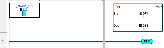
Our Click PLC program will be a simple copy from DF1 (Scaled Analog Input) to DS3 (Integer 16-bit value)
More information on our entire Click PLC series can be found here.
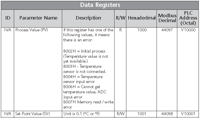
Click PLC Modbus Addresses
DS1 and DS2 will hold our Solo Present and Set values. DS3 from above will be the value that we will write into the Solo Set Value.
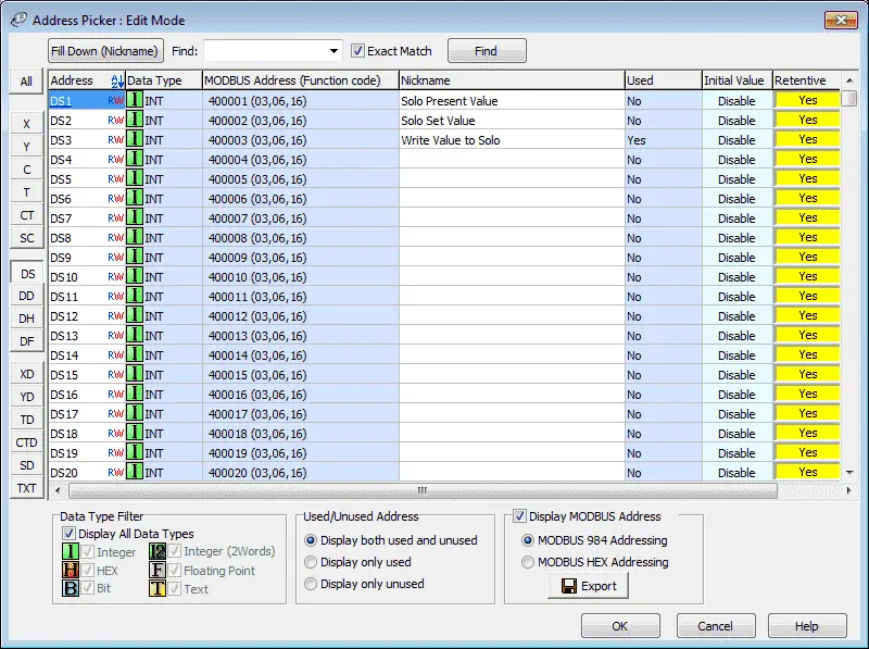
Display the Address Picker by selecting it under the Ladder Program in the Program tab of the navigation window. You can also use the main menu | Program | Address Picker or use Ctrl + T.
Select display Modbus Address on the lower right-hand side of the address picker window. You will now see the Modbus address for our memory locations and corresponding function codes that can be used.
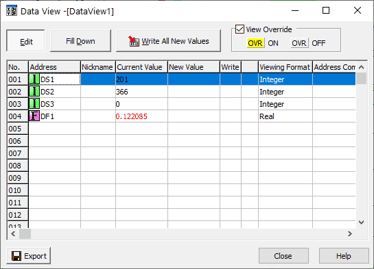
Data View can be used to monitor the memory locations and help troubleshoot our program.
A full series on the Click PLC can be found here.
Watch below to see Node-RED read and write to the Click PLC using Modbus TCP.
Node-RED Modbus Flow Program
The links listed near the end of this post will explain Modbus TCP and RTU.
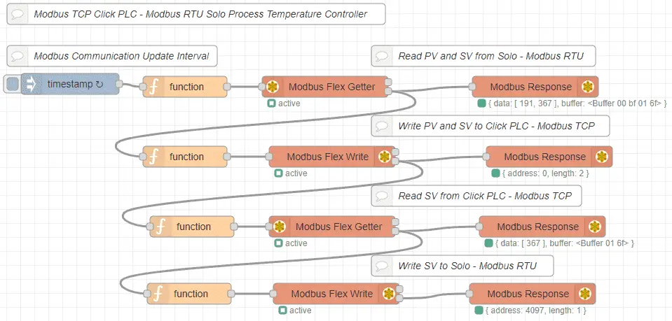
We will have one flow that will execute every 200 milliseconds. The present value (PV) and set value (SV) is read from the solo controller using Modbus RTU serial communication. The information read is then written into the Click PLC using Modbus TCP Ethernet communication. The set value from the Click analog input is then read and written into the SV value of the Solo controller.
We will now review each step in the flow.
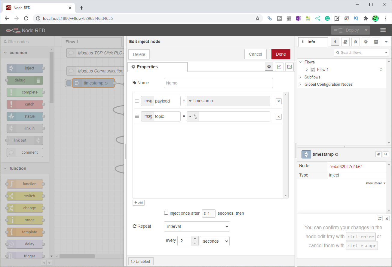
The inject node is used to start the flow every 0.2 seconds. This is only used to repeat the flow continuously.
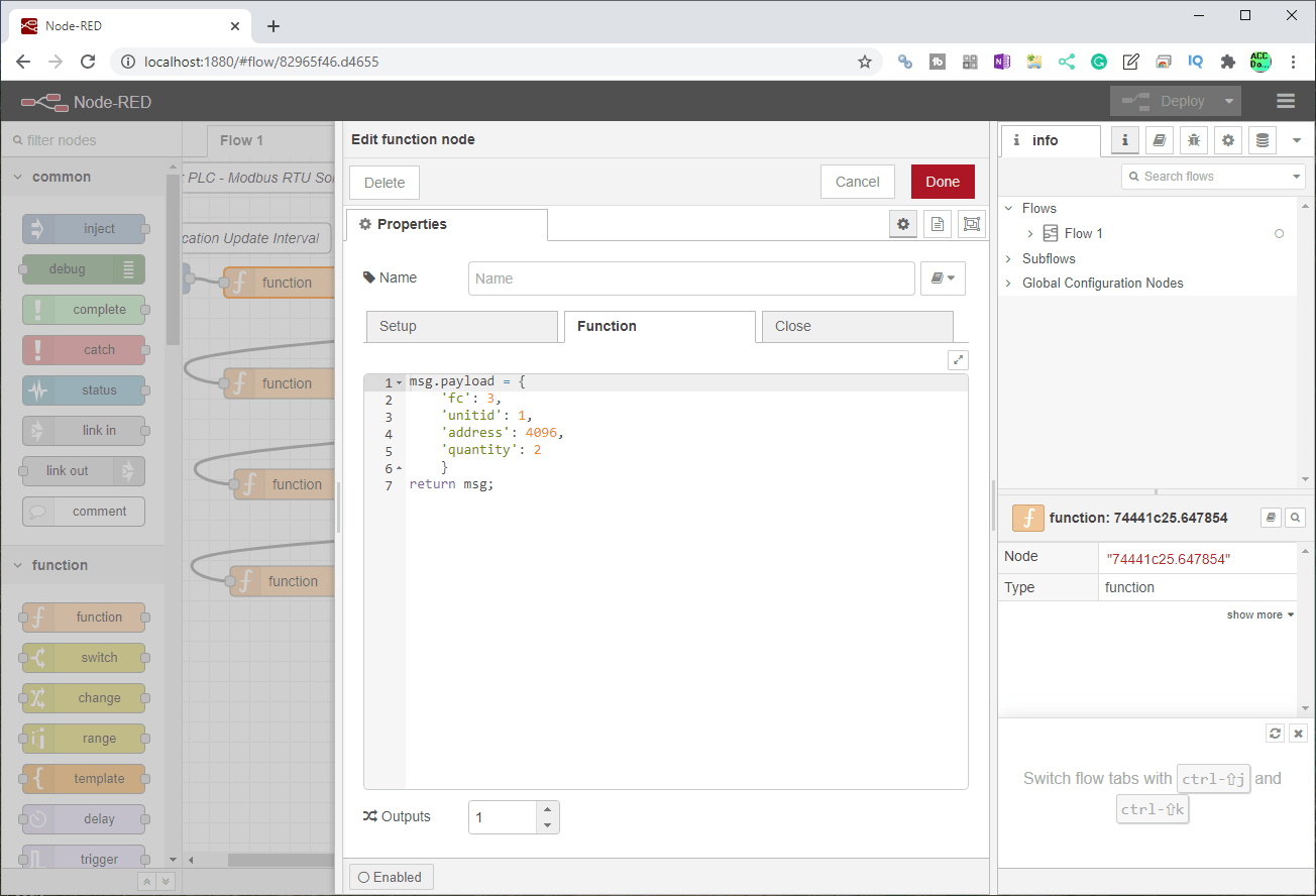
A function node is used in front of the Modbus flex getter node. The parameters that are used in the return message include the Modbus function code (FC), Modbus unit ID, Modbus address, and the number of registers.
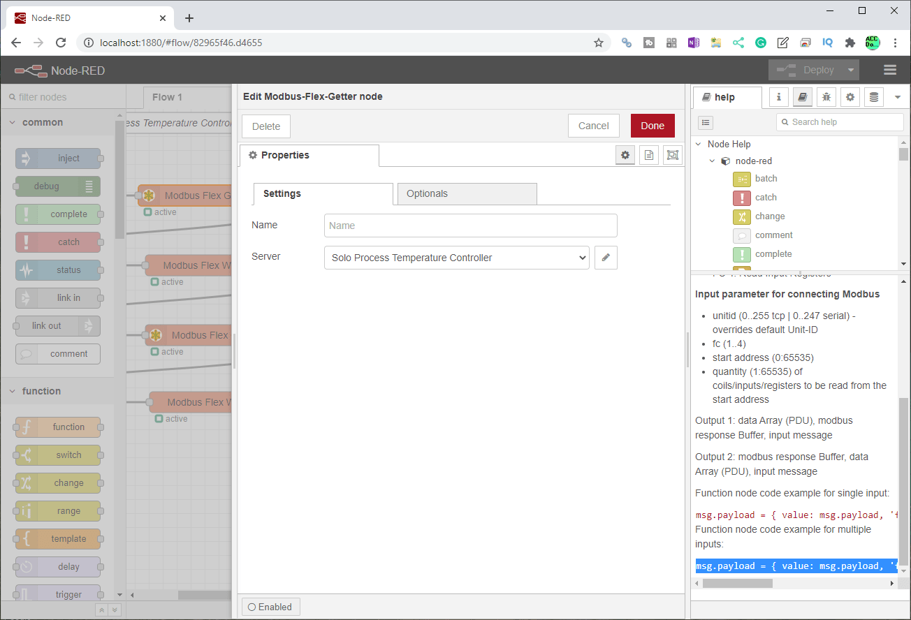
An example of the function parameters can be obtained from the help file of the Modbus flex getter node. Node-RED acts as a client to one or more servers. Click on the edit next to the server to set the parameters.
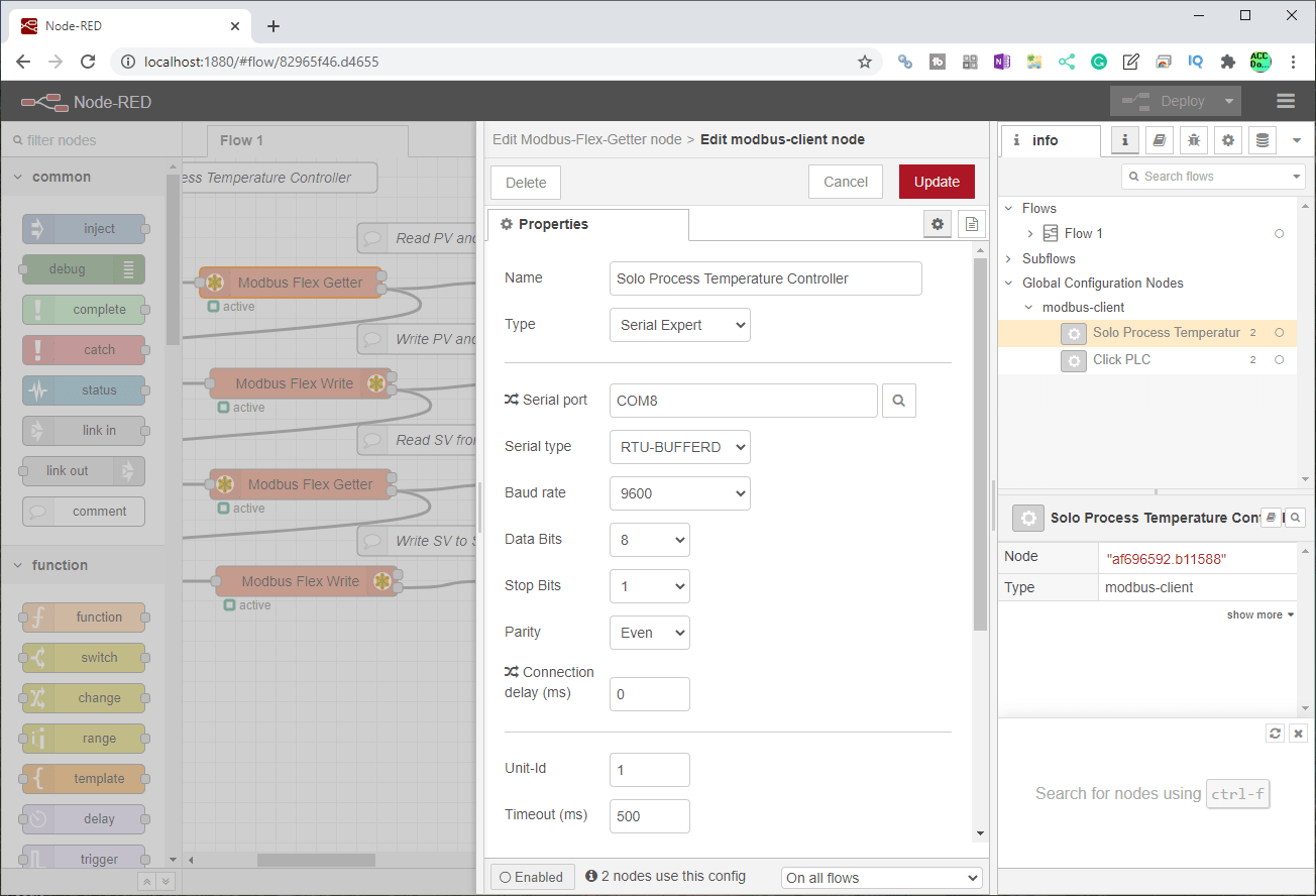
Here are our settings for the Solo process temperature controller server. The serial type is set for RTU-Bufferd. Serial communications must match what we set above for the Solo.

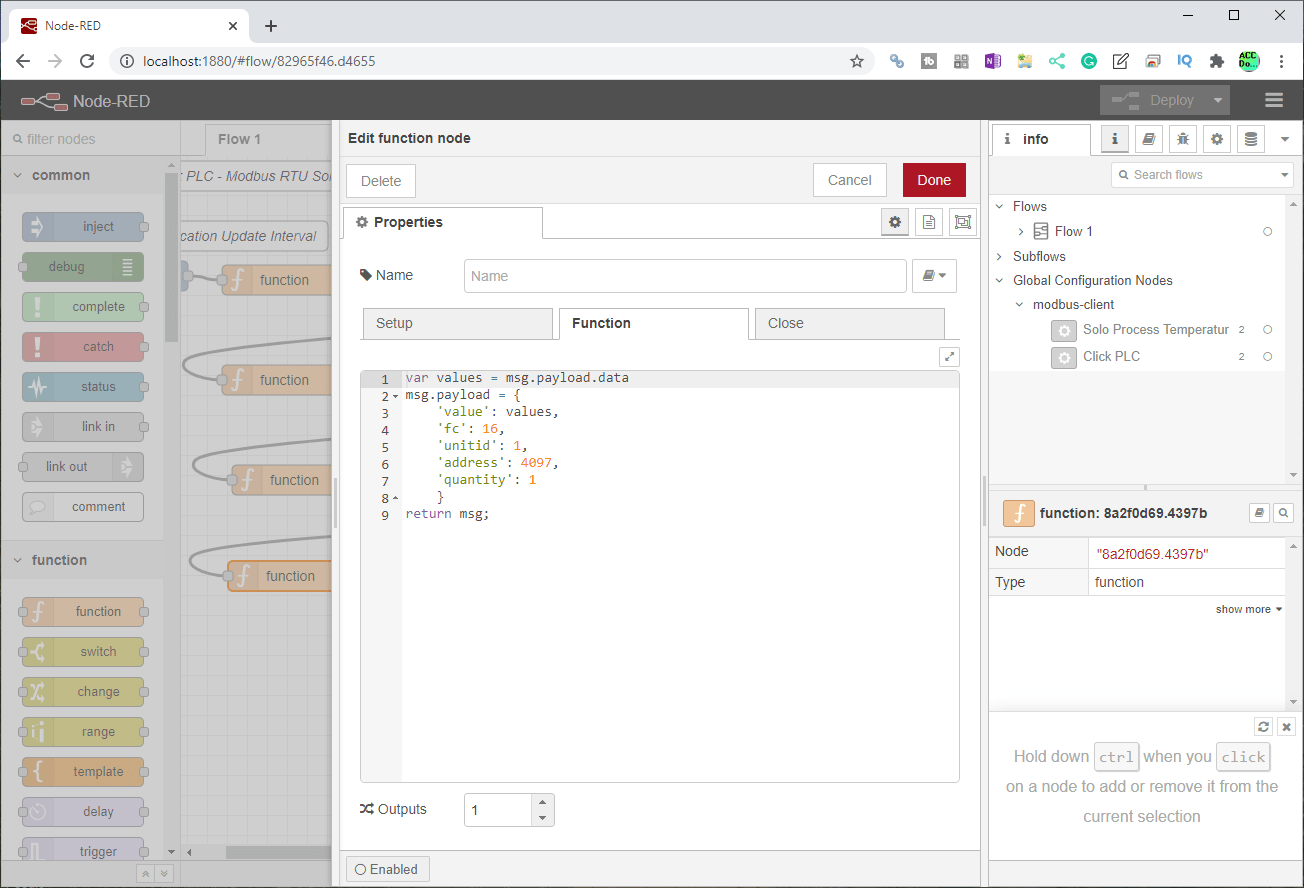
We will now write the parameters read into the Click PLC. Once again the function node is used to set the parameters for our Modbus flex write node. The message payload data is used in a variable called value. The write Modbus parameters used include the function code, unit number, address, and quantity.
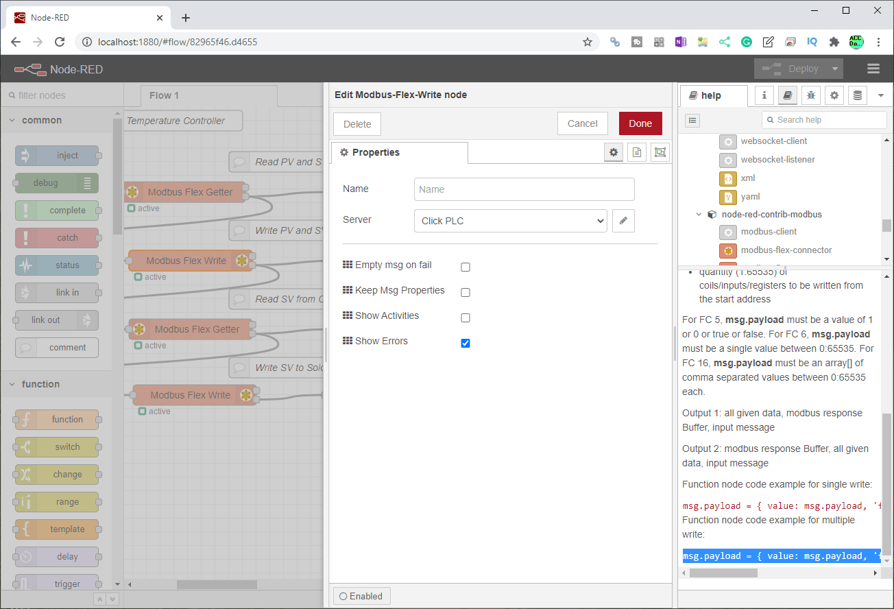
In the help file for the Modbus flex write, you will find the code for the function node that proceeds this instruction. Click on the edit for the server.
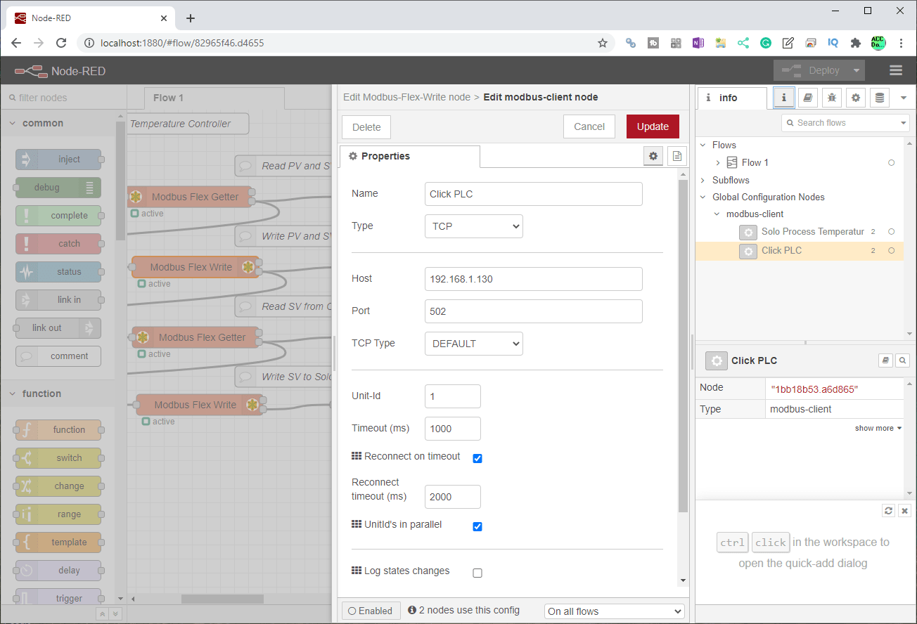
Here are the settings for the Click PLC Modbus Server. The type of client will be TCP. We will leave all of the other parameters as their default.

The analog input variable will now be read from the Click PLC at address 2. (DS3) The function node is used to set the read using the Modbus-Flex-Getter node.

Since the Click server has already been programmed, we can just select it on the server drop-down menu.
Our last function node will now set the parameters to write the SV of the Solo.
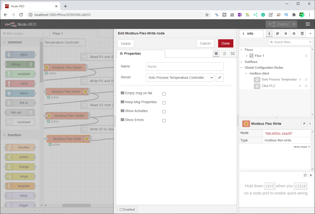
The last Modbus-Flex-Write node will use the Solo Process Temperature Controller server. Select this in the drop-down menu. We will leave the rest of the settings as their default.
Our Modbus flow is now complete. Selecting the Deploy button will put our program into operation. Watch the video below to see the operation of our Modbus flow using Node-RED.
Export and Import Node-RED Flows
Node flow programs written in Node-RED can be exported and imported easily. You will often see as you learn Node-RED a series of text characters. This is how we can save and share Node-RED programs.
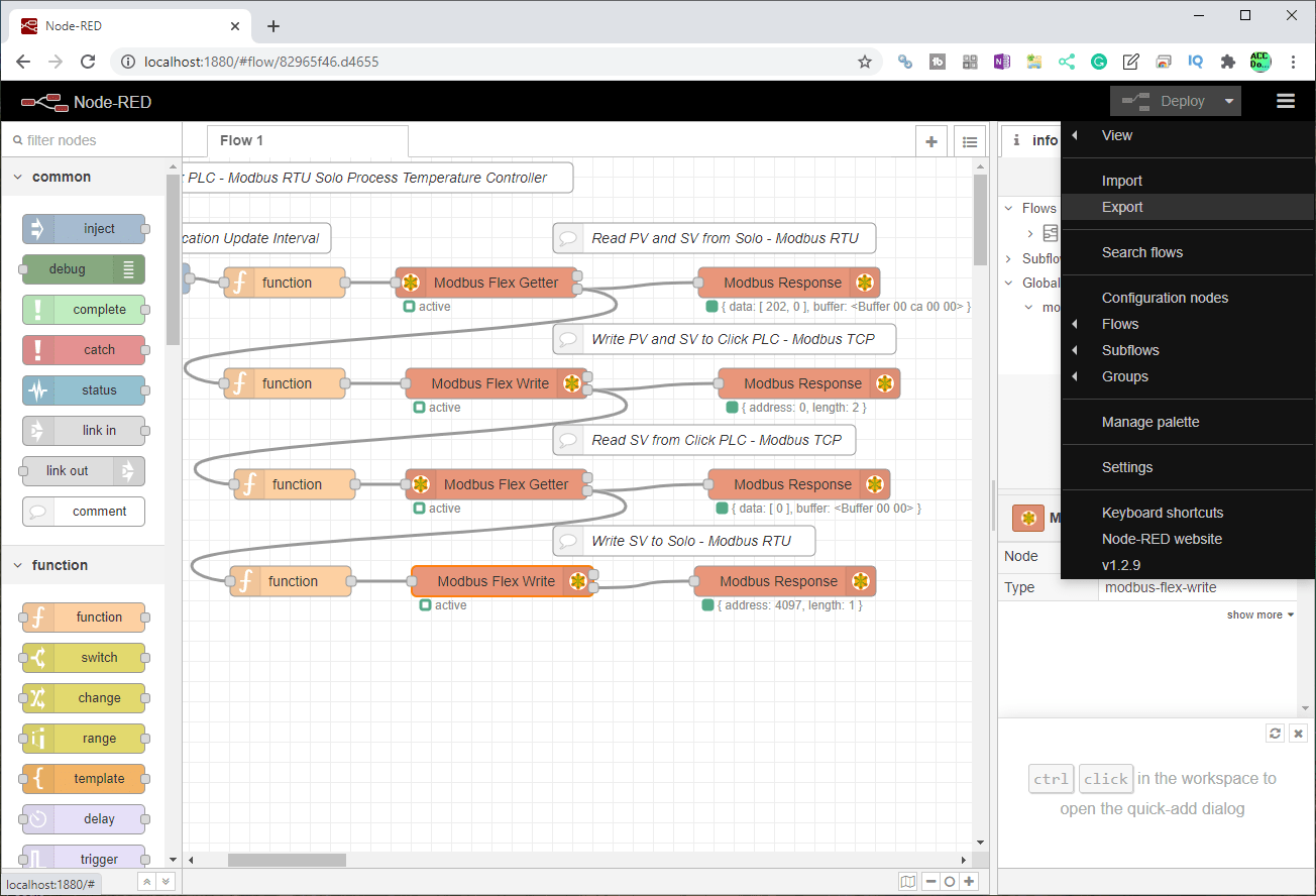
On the title bar, click the three parallel lines to the right-hand side and select Export.

The export node window will now be displayed. You can now use this to download, copy to a clipboard, etc.
Importing is just as easy.

Select Import from the main menu.
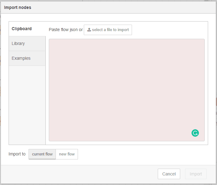
The import nodes window will now be displayed. We can now paste the copied information and select the import to current flow or new flow.
Watch the video below to see Modbus communication using Node-RED to our Solo and Click controllers.
Download the Click Program and Flow here.
Node-RED Links
Node-RED Organization Home Page
Getting Started – Run Locally
Node-RED Running on Windows (Run at Startup)
Securing Node-RED
Node-RED Essentials Videos (Basics of the Editor)
Learn JavaScript Free
w3schools JavaScript Tutorial
learn-js.org
Node-Red JavaScript Primer
Modbus
Node-RED Modbus TCP and Serial
Dashboard – HMI
Node-RED Dashboard
Node-RED Dashboard extra nodes
SQL Database
Node-RED SQL Database
Node-RED SQL Plus – Execute queries and stored procedures
Modbus Learning Links:
Simply Modbus Frequently Asked Questions
Modbus TCP/IP Overview – Real-Time Automation
All You Need to Know About Modbus RTU – Video
Next time we will be display Information on a user interface using Node-RED. This is also known as an HMI or dashboard.
Watch on YouTube: Node-RED Modbus RTU / TCP Communication
If you have any questions or need further information please contact me.
Thank you,
Garry
If you’re like most of my readers, you’re committed to learning about technology. Numbering systems used in PLC’s are not difficult to learn and understand. We will walk through the numbering systems used in PLCs. This includes Bits, Decimal, Hexadecimal, ASCII, and Floating Point. To get this free article, subscribe to my free email newsletter.
Use the information to inform other people how numbering systems work. Sign up now. The ‘Robust Data Logging for Free’ eBook is also available as a free download. The link is included when you subscribe to ACC Automation.