PLC (Programmable Logic Controller) programming is a crucial aspect of industrial automation, yet many individuals struggle to grasp its fundamental concepts. This guide will dive into the key principles of PLC programming that are often misunderstood, shedding light on these concepts and providing clarity for beginners and experienced professionals. By addressing common misconceptions and exploring the core principles of PLC programming, we will aim to demystify this essential aspect of industrial control systems.
Whether you’re new to PLC programming or looking to refine your understanding, this will serve as a valuable resource to deepen your knowledge and proficiency in this essential field. Sometimes, I wish that I had some of this knowledge before my first PLC program.
Part 1 will discuss the PLC Scan Cycle and Ladder Logic. These are some common areas where people often struggle. Let’s get started.
The following PLC Concepts are also explained in the following posts:
PLC Learning Series – Program Cyclic Scan – Video
What are the Different PLC Programming Languages – Video
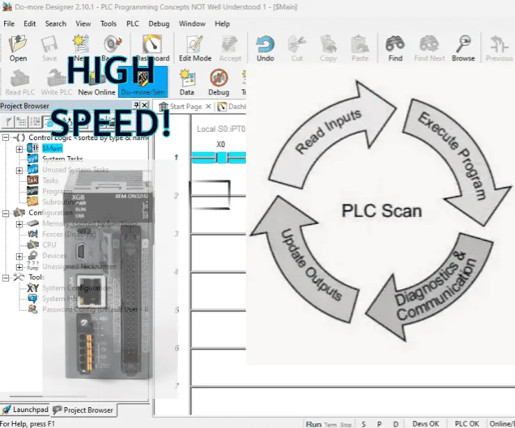
PLC Concepts 1. Scan Cycle
Understanding how the PLC program scans will help us program and troubleshoot the PLC.
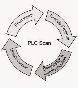
The most straightforward scan cycle of a PLC consists of 4 steps. Read inputs, execute program(s), diagnostics and communication, and update outputs.
Programmable logic controllers (PLC) use a cyclic scan. This means that the PLC is not waiting for an input condition to change from one state to another. It constantly looks at the condition of the inputs and makes a copy of that in memory. The time that it takes to complete one scan is called Scan Time. Typical scan times range from 10 milliseconds to 10 microseconds. This translates from 0.01 to 0.0001 seconds per PLC scan.
Once the PLC inputs are read, the program or programs are executed. The program will read the memory area for the inputs and set the memory areas for the outputs as it executes your instructions. Programs can be written in several different languages depending on the controller used. Standardization, such as IEC, has set five official PLC languages for programming:
- Structured Text (ST)
- Function Block Diagram (FBD)
- Sequential Function Chart (SFC)
- Instruction List (IL)
- Ladder Diagram (LD)
When the scan of your program is complete, the PLC will then handle communications and diagnostics. Internal diagnostics will ensure that the PLC continues to scan the logic and no errors are detected. These are system errors such as memory integrity and execution timing. Communication is for external devices such as programming software, HMI (Human Machine Interface), etc.
The final step of the PLC scan is to update the outputs. Output internal memory is then copied to the physical outputs, and the scan cycle begins again.
Every PLC controller has this essential operation. However, some will have additional instructions to help you with your application if the input signal you are looking at is faster than the scan time of the cycle. This can be handled with PLC instructions to update the physical IO within the program’s scan or a separate processor operating input and output settings independent from the main PLC scan.
This is usually referred to as a high-speed counter. Understanding the timing and order of operations is crucial within the PLC controller. This will help to understand and correct unexpected behavior in time-sensitive applications.
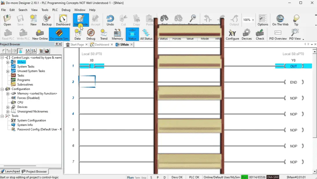
PLC Concepts 2. Ladder Logic
Ladder Diagram (LD) is the most popular programming language for PLC. It was written to mimic the mechanical relays in the panel that the programmable logic controller replaced. It has two vertical rails and a series of horizontal rungs between them. This looks like a flowchart or ladder. Contacts or inputs are on the left side of the rung. If the conditions are “true” or “on,” this creates a flow, turning on the outputs on the right side of the rung. Controllers usually execute the ladder logic program from left to right, top to bottom. The output of one rung is available for the next rung.
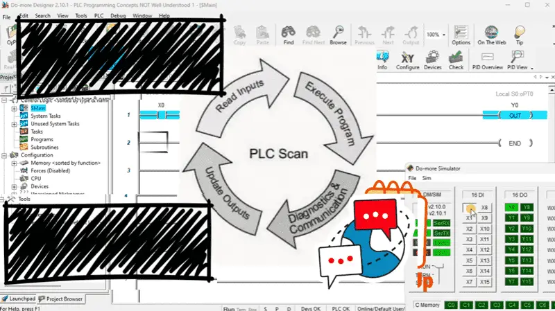
The common misconception about the ladder logic program is the sequential evaluation of rungs and how specific conditions influence program flow. We know that the scan cycle of the PLC is cyclic. Inputs are scanned and put into an internal memory location. This means that the PLC program can manipulate this input table.
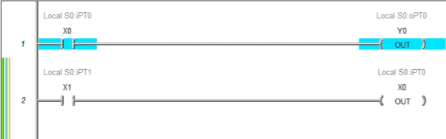
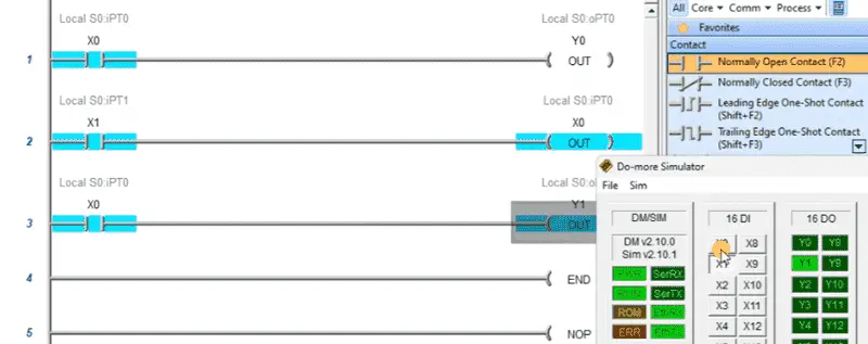
The second rung of our sample program will set the input X0 as an output based on the X1 input.
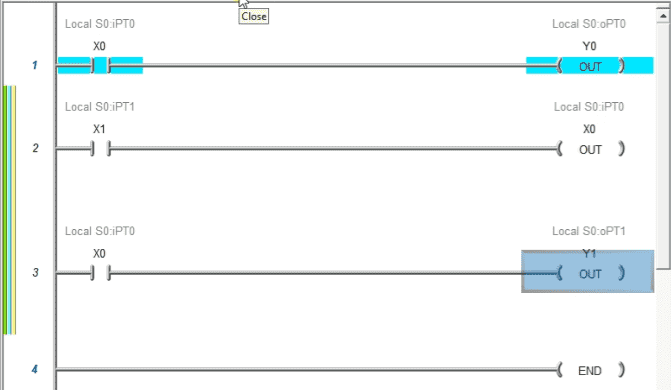
When we use the X0 as an input condition on rung 3, you will see that this is based on input X1.
At the beginning of the ladder logic execution, X0 will turn on Y0. X1 input will now control the value of bit X0 in memory in rung 2. Rung 3 will control Y1 based on the input X0.
You can see that basic ladder logic concepts seem simple at first, but understanding the program execution is essential for troubleshooting and programming in this language.
If any of these or other topics are unclear, please ask for a deeper explanation or examples, and we will break them down further. If you find specific PLC programming concepts challenging, let me know, and I can help clarify them.
To learn how to use the free Do-More Designer programming software we used in this video, click here.
Download the Sample Do-More Designer Ladder Logic Code here.
To learn more about the actual PLC and its development, click here.
Watch the video below on the scan time and ladder logic.
PLC Beginner’s Guide to PLC Programming
Many different PLC manufacturers use other hardware and software. All of the programmable logic controllers have similar basic features. Here is how I would approach learning about basic PLCs.
Once you are familiar with the basics of the PLC, you will then learn specifics for the controller you will be programming.
This is the easiest way to learn about PLC programming.
Watch on YouTube: PLC Programming Concepts NOT Well Understood Part 1
If you have any questions or need further information, please get in touch with me.
Thank you,
Garry
If you are like most of my readers, you are committed to learning about technology. Numbering systems used in PLCs are not complex to understand. We will walk through the numbering systems used in PLCs. This includes Bits, Decimals, Hexadecimal, ASCII, and Floating Points.
To get this free article, subscribe to my free email newsletter.
Use the information to inform other people how numbering systems work. Sign up now.

‘The ‘Robust Data Logging Free’ eBook is also available for free download. The link is included when you subscribe to ACC Automation.