The Trumeter ADM100 Series Graphical Panel Meters provide the visual representation of an analog meter and the accuracy of a digital meter all in one unit.
These meters feature a programmable bar graph and alarms to immediately alert operators when a parameter is out of range. In addition, a four-character messaging area displays custom messages, alarms, and annunciators.
Every meter is configurable to measure voltage, current or frequency. The M100-Lx model is for use with a low voltage power supply, and the ADM100-Hx is for use with mains power. Both models offer two LCD options – positive LCD for bright conditions or negative LCD for dark environments.
We will be looking at unboxing the unit, powering it up, installing the software, and setting and communicating to the Trumeter AMD100 Series Graphical Panel Meter. Let’s get started.
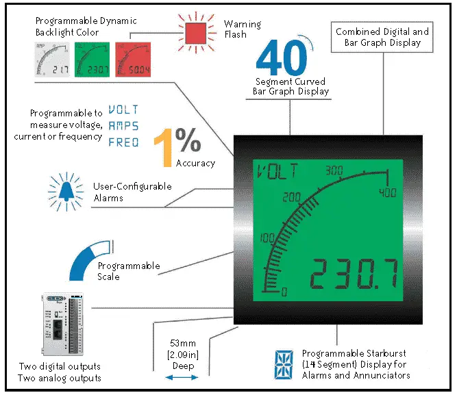
Trumeter ADM100 Panel Meter Key Features
– Large multi format display
– 40 segment bar graph display
– Large 4 digit display
– Separate display area for annunciators, custom message and alarm information.
– Dynamic backlight colour
– User adjustable backlight brightness, flash and colour
– Wide viewing angle (Horizontal and Vertical)
– Three year warranty
Overview – Trumeter ADM100 Panel Meter
– Measurement
o Voltage 0-600 AC or DC
o Current 0-5 A direct, 0-9,999 A via CT
o Frequency 2-400 Hz
– Outputs
o 2x digital open collector
o 2x analog 4-20 mA
– Input Power
o ADM100-Lx: 12-24 VAC/VDC (+/- 10%)
o ADM100-Hx: 100-240 VAC or 110-300 VDC (+/- 10%)
– Free Configuration Utility Download
o PC utility via USB
o Basic configuration without PC (default setting is volts)
– Display Options
o Positive LCD (bright environments)
o Negative LCD (dark environments)
– Programmable
o Scale (offset and gain) and Range (min and max)
o Four-character starburst for custom annunciators
o User-selectable backlight colour and intensity
o Two independent alarm set-points
o Two independent outputs
o 4-20 mA analog monitor output
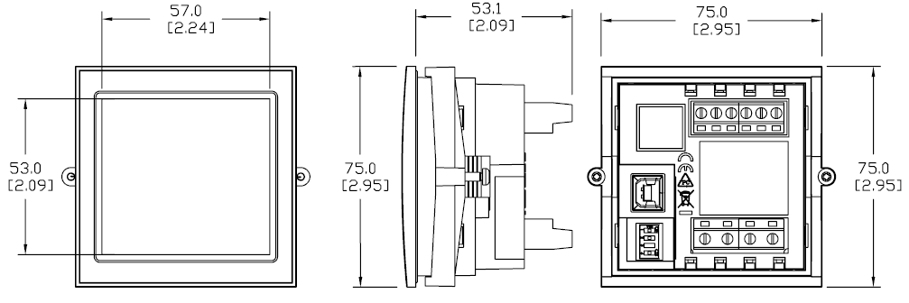
Dimensions – Trumeter ADM100 Panel Meter
mm [inches]
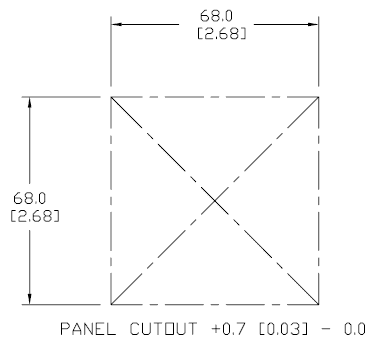
This unit is a panel mountable device. Here are the panel cut out dimensions.
Watch on YouTube: Trumeter ADM100 Series Graphical Panel Meter – Unboxing the Unit
Wiring Diagrams – Trumeter ADM100 Panel Meter
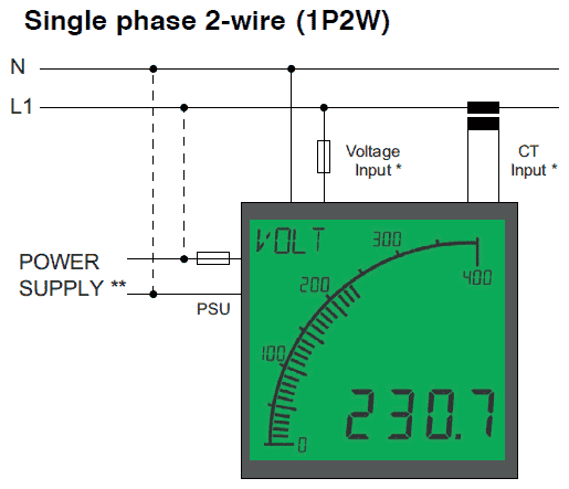
* Both connection options shown. User must select one (volts, amps or frequency) to be displayed.
** Dotted lines show 100-240 VAC power option on ADM100-Hx models. ADM100-Lx units use the 12-24 VAC/VDC PSU connection shown.

We will be using a 9V DC Battery as our input voltage to the ADM100 series panel meter.
This is the same tester that was discussed in our post: Create an Analog Voltage Input Tester for a PLC.
Here is a link to the video on creating an analog voltage input tester.
Watch on YouTube: Trumeter ADM100 Series Graphical Panel Meter – Powering the unit
Trumeter ADM configuration utility download
The Trumeter ADM Graphic Panel Meter Configurator Utility software can be downloaded at the following URL:
https://support.automationdirect.com/downloads.html#tools
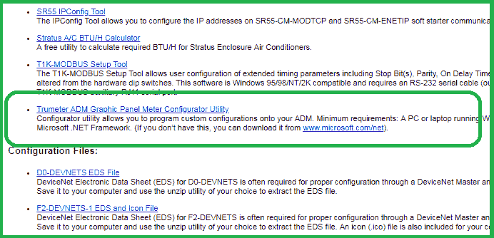
This will download the trumeteradm_config.zip file.
Installing the Trumeter ADM Configuration Utility Software
Inside the zip file downloaded above, you will see the windows installer package. This is called ADM100 Series Configurator R01.msi.
Double click this to start the software installation.
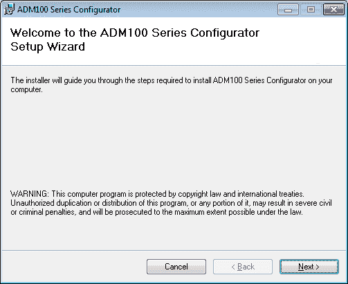
The welcome screen will be displayed. Click Next to continue the installation.
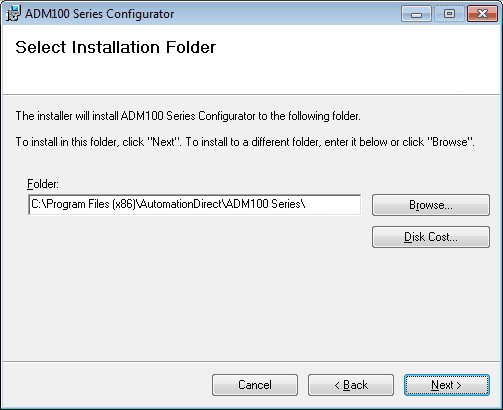
We can now select the installation folder. In our case, we will leave this as the default and select next.
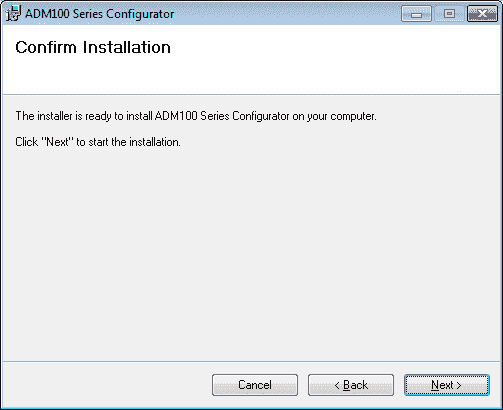
Confirm Installation window will now appear. Click Next to start the installation.
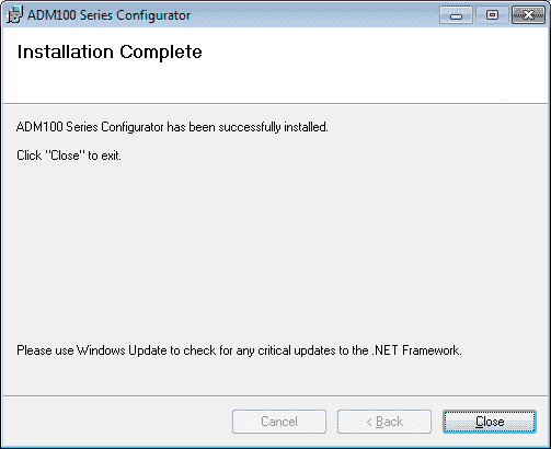
Installation Complete window will now be displayed. We have now installed the software onto the computer. Click close to end the installation.
The above icon is placed on the computers desktop. You can start the software by double clicking this icon.
Watch on YouTube: Trumeter ADM100 Series Graphical Panel Meter – Installing the software
Watch the video below for the configuration of our ADM100 Series Graphical Panel Meter using the software that we just installed.
Configuring the Trumeter ADM100 Panel Meter using software
Start the ADM100 Series Configurator software by double-clicking the icon on the desktop.
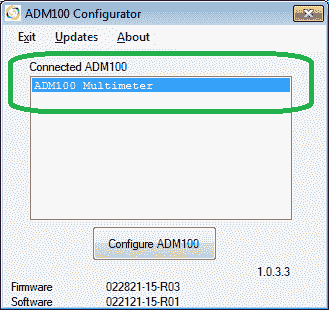
If the USB (AB – Printer) cable is connected to the ADM100, then you will see it listed under the Connected ADM100 list.
Hit the Configure ADM100 button.
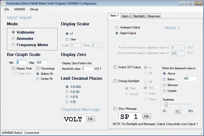
Input Signal – Here we program the basic information for the ADM100.
Mode – This is set for Voltmeter, Ammeter or Frequency Meter depending on the signal that you are wiring to the input. In our case we will leave this as the default Voltmeter.
Display Scalar – We can set the scaling of our input signal to reflect what the physical input is actually measuring. We will leave this as X1 or no scaling because we are wiring our battery voltage directly to the input. (0 – 9 VDC)
Display Zero – The display will zero if the value measured is below this value. This is to ensure that if you have a value around zero you are not just reading the noise of the line. We will leave this as the default of 0 volts.
Limit Decimal Places – This will determine the number of decimal places that will be displayed. In our case we will select 2 (0.00)
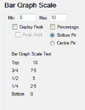
Bar Graph Scale – This will display the min and max of the bar graph scale. In our case we will set this at 0 min and 10 max to represent the 0-9 volt battery.
Display Peak – Selecting this will display the maximum reading on the input. This can be reset by wiring in the reset signal.
Percentage – If selected this will display the percentage on the bar graph scale. In our case we will leave this as the default.
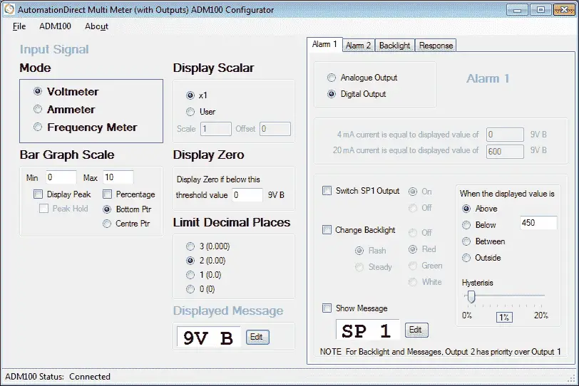
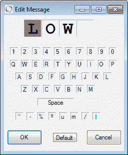
Display Message – Hitting the edit button, we can set a four character display on the ADM100. In our case we will enter “9V B” for our 9 VDC Battery.
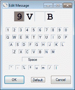
Hit OK to return to the main screen.
Our input signals are now programmed into the software.
Alarm 1
Alarm 1 is on the first tab to the right of the input signal selection.
Analogue or Digital output can be selected for the alarm. In our case we will use the Digital Output.
Select Switch SP1 Output On. This will turn the output on when the alarm is triggered.
Select Change Backlight – Select Steady and Red. When the alarm occurs the backlight is changed to a steady red colour.
Select Show Message. We can now edit the Alarm 1 message that will show when activated. (LOW)
When the display value is Below 3 we want the alarm to be on. The Hysteresis is used so that the output will not chatter. We will leave this as the default of 1%.
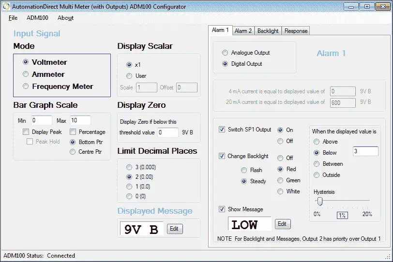
Here is our completed Alarm 1 screen.
Alarm 2
Alarm 2 is on the first tab to the right of the input signal selection.
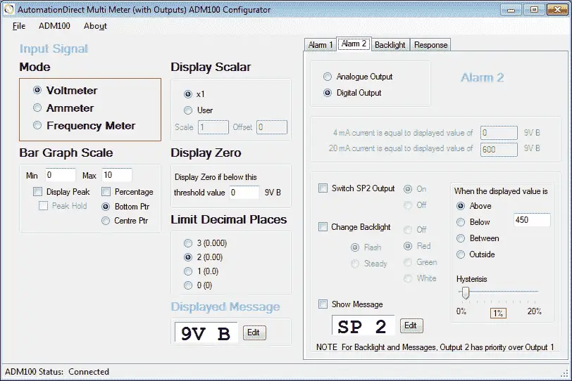
Analogue or Digital output can be selected for the alarm. In our case we will use the Digital Output.
Select Switch SP2 Output On. This will turn the output on when the alarm is triggered.
Select Change Backlight – Select Steady and Green. When the alarm occurs the backlight is changed to a steady green colour.
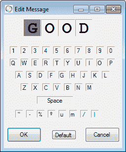
Select Show Message. We can now edit the Alarm 2 message that will show when activated. (GOOD)
When the display value is Above 7 we want the alarm to be on. The Hysteresis is used so that the output will not chatter. We will leave this as the default of 1%.
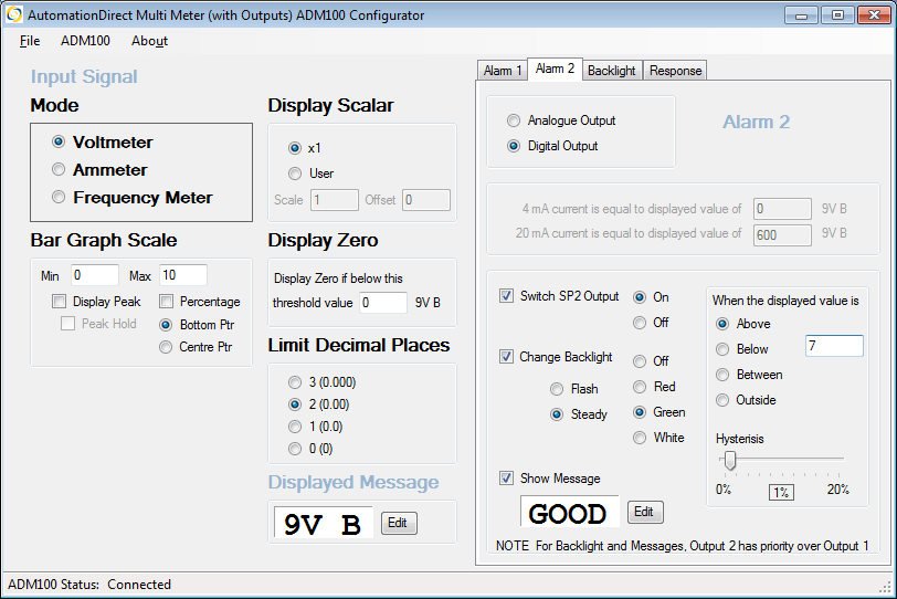
Here is our completed Alarm 2 screen.
Note: Backlight and Messages, Output 2 has priority over Output 1.
Backlight
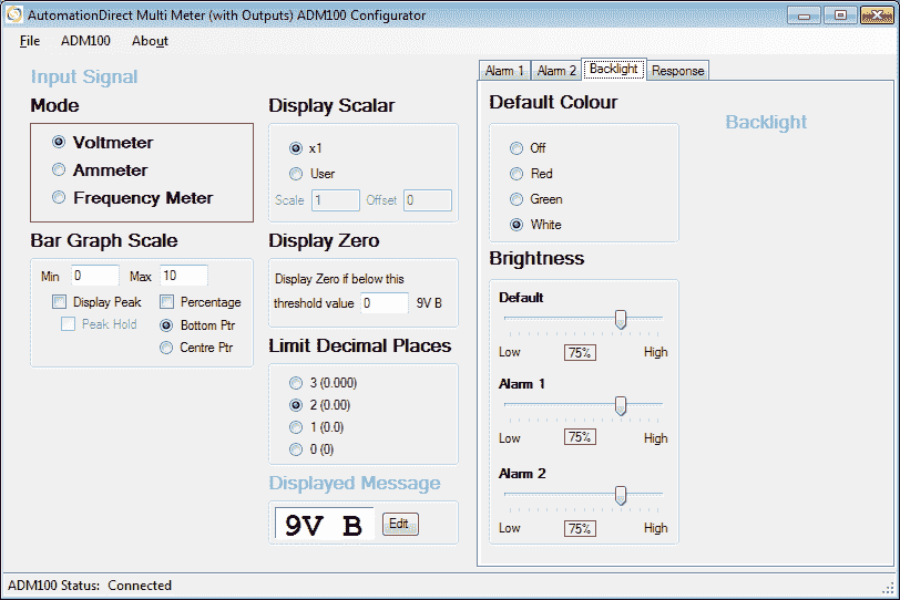
This is the default backlight colour. We can also set the brightness of the default, alarm 1 and alarm 2 screens. Experiment with these settings to suit your location that you are installing this ADM100 Graphical Panel Meter.
Response
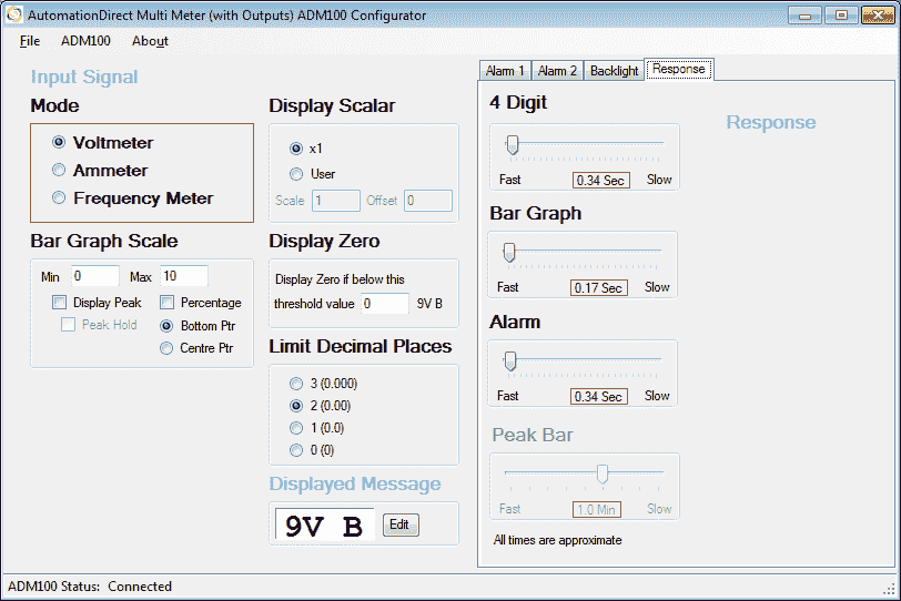
This will set the response of the display digits, bar graph and alarms so that you will not see some quick fluctuations on your system. Set these to ensure that you do not get false alarms.
Saving your configuration
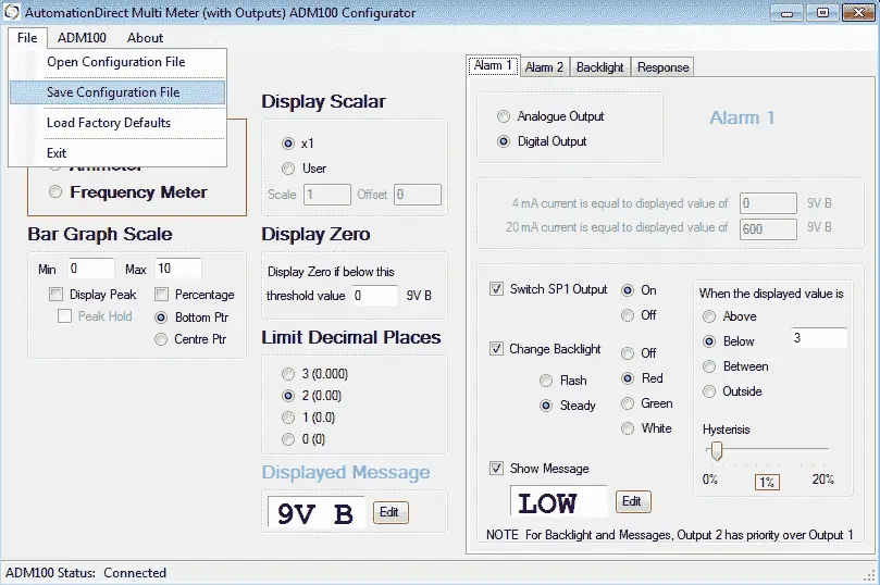
Using the main menu | File | Save Configuration File. We can save our configuration as Battery.cfg.
You will also see under the file menu the options to open a configuration file, load factory defaults and exit the program.
Transferring
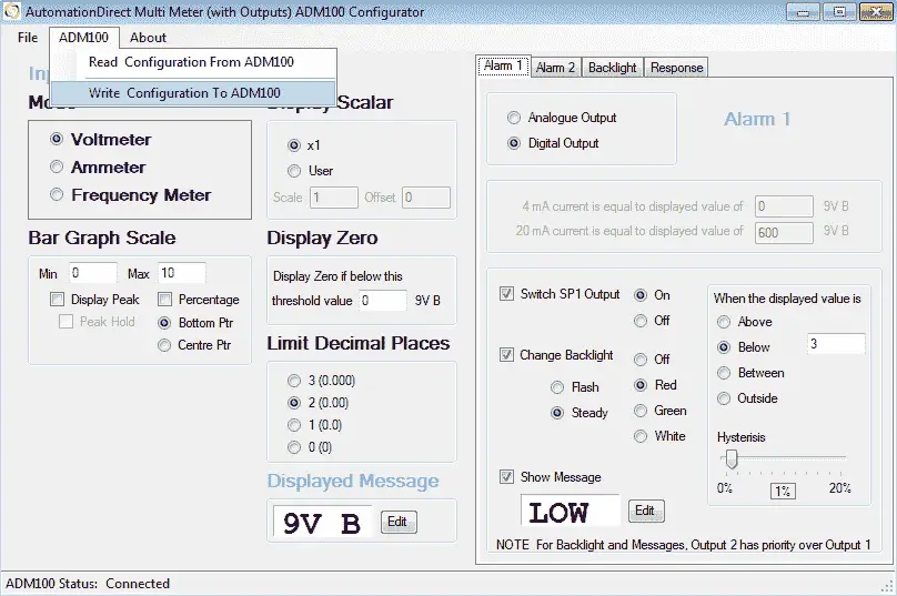
To write the configuration to the ADM100 select this from the main menu, and then select Write Configuration To ADM100.
Watch on YouTube: Trumeter ADM100 Series Graphical Panel Meter – Configuring the unit
Trumeter ADM100 Series Graphical Panel Meter Links
Product Overview
Trumeter Graphical Panel Meters Inserts
Trumeter ADM Series Specifications
Trumeter ADM Configuration Software
If you have any questions or need further information please contact me.
Thank you,
Garry
If you’re like most of my readers, you’re committed to learning about technology. Numbering systems used in PLC’s are not difficult to learn and understand. We will walk through the numbering systems used in PLCs. This includes Bits, Decimal, Hexadecimal, ASCII and Floating Point.
To get this free article, subscribe to my free email newsletter.
Use the information to inform other people how numbering systems work. Sign up now.

The ‘Robust Data Logging for Free’ eBook is also available as a free download. The link is included when you subscribe to ACC Automation.