In part 1, we looked at writing PLC programs to control a traffic light using discrete bits and timed sequencing using indirect addressing. We will now look at how we can use indirect addressing for inputs and output to control the sequence in the program.
Let’s look at an example of controlling pneumatic (air) cylinders.
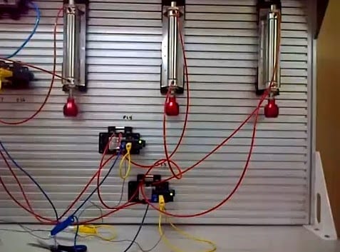
This site contains a video of the three cylinders and the sequence required.
This program will have the following inputs. Even though no sensors are mounted on the cylinders, it is best to have sensor inputs when the cylinder is extended (out) and retracted (in)
Inputs:
Cylinder 1 In – X1
Cylinder 1 Out – X2
Cylinder 2 In – X3
Cylinder 2 Out – X4
Cylinder 3 In – X5
Cylinder 3 Out – X6
Start PB NO – X7
Stop PB NO – X8
Step PB NO – X9
This program will have the following outputs.
Outputs:
Cylinder 1 In – Y1
Cylinder 1 Out – Y2
Cylinder 2 In – Y3
Cylinder 2 Out – Y4
Cylinder 3 In – Y5
Cylinder 3 Out – Y6
We will use the following pointers:
V0 – Output pointer starting at address V2000
V1 – Input pointer starting at address V1000
V10 will be the input word
V20 will be the output word
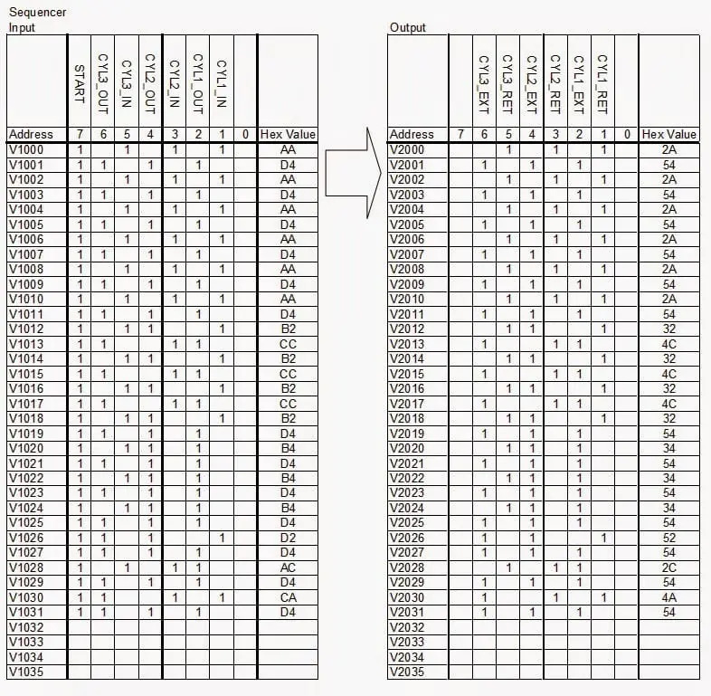
Before we start and write the code, let’s look at the sequence we are trying to accomplish. AI uses either graph paper or spreadsheet software to configure the sequence. A chart indicating the inputs and output is the best way to do this.
I usually start with the outputs and configure the sequence that I would like to see. Then based on the output sequence, I figured out the input sequence.
Note: Here is the location for a quick review of numbering systems from a previous post.
Once the sequence has been established, the next step is writing the program.
Input program that will set the input bits in V10.
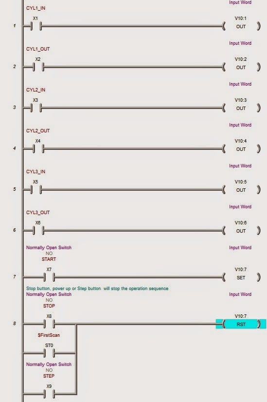
The control part of the program:
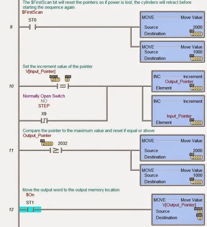
The first scan will reset the input and output pointers.
The input pointer is compared to the input word V10. If they are equal, then the output and input pointers are incremented. If the STEP input is hit, the output and input pointers are incremented.
The output pointer is then compared to the maximum value (end of the sequence). The pointers will be reset if it is greater than or equal to the maximum value.
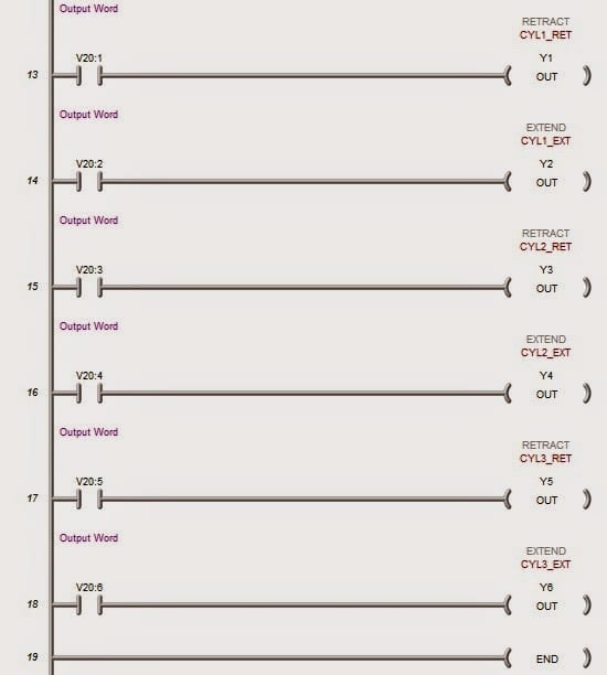
Line 12 will move the outputs indirectly to the output word.
Output program that will set the actual outputs based on the bits in V20
As you can see, the actual program is tiny; however, the sequence can be thousands of steps. This is a very straightforward and powerful method of programming. Programming this sequence using bits, timers, and no indirect addressing would be very difficult to read. Modifications would have to be a complete rewrite of the program.
Modifications:
The entire program sequence could change without further lines of code. Only the values in the registers would need to be modified. This could lead to different sequences for different products.
We used a step input to move the program through the sequence. It would be just as easy to add a step reverse function for the program. We would have decrement the pointers and checked to make sure when we were at the beginning of the sequence.
Troubleshooting:
When troubleshooting this program, we only need to look at the compares to determine what input or output is not working correctly.
Integration with a touch panel display is simplified using this programming method.
What other advantages do you see?
In Part 3, we will build on the traffic light sequencing used in part one with inputs for pedestrian and car detection.
Contact me for the above program. I will be happy to email it to you.
If you have any questions or need further information, please get in touch with me.
Thank you,
Garry
You can download the software and simulator for free at the following address. Also listed are helpful guides to walk you through your first program.
Do-more Designer Software
How to use videos for Do-more Designer Software
If you’re like most of my readers, you’re committed to learning about technology. Numbering systems used in PLCs are not challenging to learn and understand. We will walk through the numbering systems used in PLCs. This includes Bits, Decimals, Hexadecimal, ASCII, and Floating Points.
To get this free article, subscribe to my free email newsletter.
Use the information to inform other people how numbering systems work. Sign up now.

The ‘Robust Data Logging for Free’ eBook is also available as a free download. The link is included when you subscribe to ACC Automation.