In part 1, we looked at writing PLC programs to control a traffic light using discrete bits and timed sequencing using indirect addressing. Part 2 used indirect addressing for inputs and output to control the program’s sequence of pneumatic (air) cylinders. Part 3 returned to the traffic light application and expanded our program significantly. We looked at the sequence of operations using Input, output, and mask tables. Part 4 will now continue with the programming of the logic in the PLC.
Let’s look at the sequence we control – Building a PLC Program – Traffic Light.
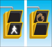
Note that I have color-coded the outputs that will be in the sequence. This makes it easier to read how the lights will behave. All bits without ‘1’ are assumed to be ‘0’. The pedestrian walk signals flash before they change to walk signals.
The weekend sequence looks like this. We have an overlap of the red signal lights. The arrows are not used.
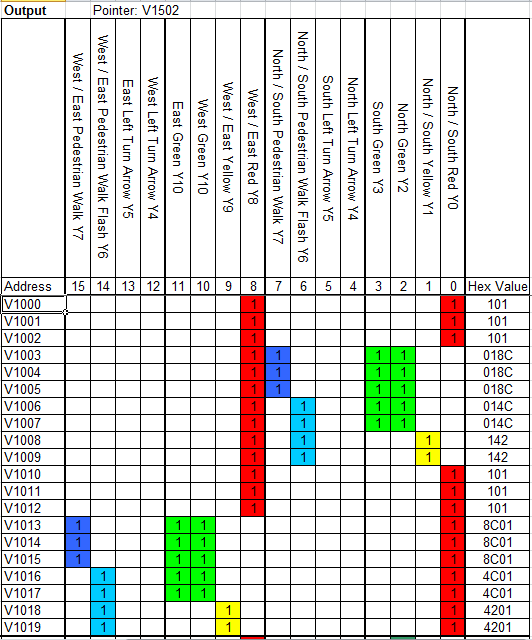
The weekday off-peak times sequence looks like this. We have an advanced flashing green light for the north and west traffic.
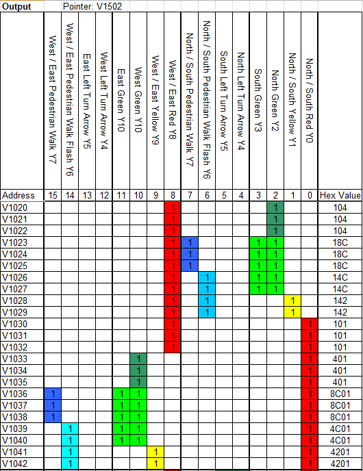
The weekday peak times sequence is as follows. The turn arrows have been added for the north/south and west/east directions.
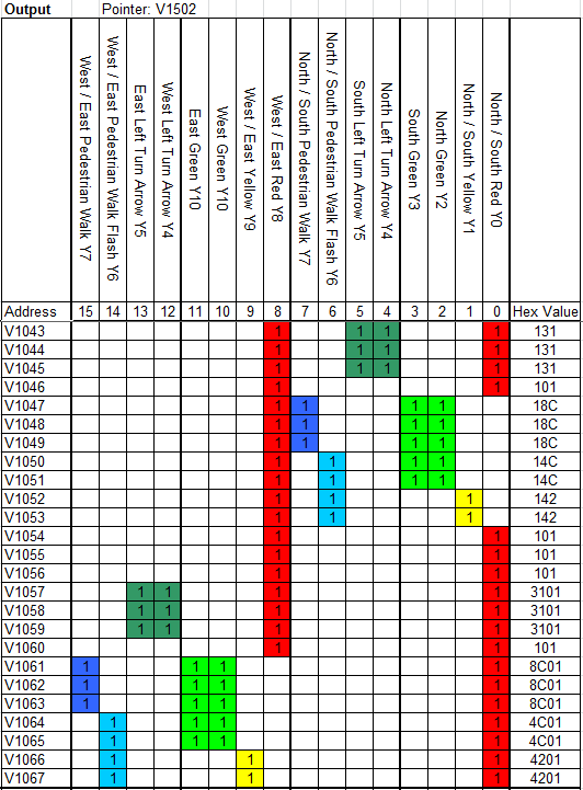
It is important to note that the sequencing and information contained in these charts must be understood fully before programming can begin. Take the time to review and understand the following tables. Here is a copy of the excel table complete with the inputs, mask, and outputs.
Advantages of Sequencers – Building a PLC Program – Traffic Light
This method of programming can have a vast number of applications. Here are some of the advantages of using this method:
- Modification of the program without extensive rewriting
- Integration with a Human Machine Interface (HMI) to control, modify and troubleshoot
- Ability to sequence forward and backward
- I quickly understood the logic to follow. Looking at the pointers, the compare instruction will promptly tell you what sensor is not being made.
Troubleshooting this method of programming is easily done. Compare the bits in the input pointed word to the actual bits form the input in binary format. The difference is the input/output that is not working.
The program is broken down into three sections:
- Inputs – Setting bits in the input channel based on actual and internal conditions.
- Control – Control of the output channel’s pointers, mask, and setting.
- Outputs – Using the output channel to activate the actual and internal actions required.
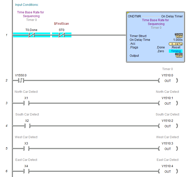
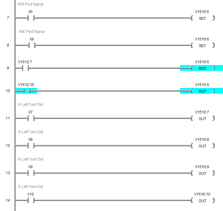
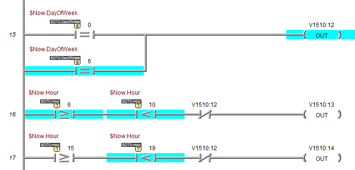
Inputs – Building a PLC Program – Traffic Light
The program is all controlled by one on-delay timer. This sets the minimum time between each step.
Control – Building a PLC Program – Traffic Light
This section of the control will tell the PLC what to do when the unit is first powered on. It resets the pointers and moves the initial output setting to the output word. The table input pointer is compared to the last value +1 of the sequence running. You will see that since we have three different sequences running, there are three different reset rungs in parallel.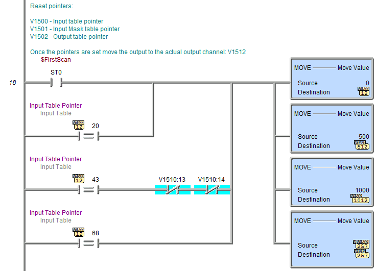
The mask calculation is next. This is used to ignore the inputs that we do not want to see or may not know the status of during the execution of the program. 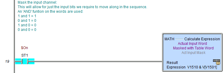
You will notice that the first three sequences are all the same. The first is for weekday off-peak times. n this step, we then determine if the pointers need to be changed for the other two. 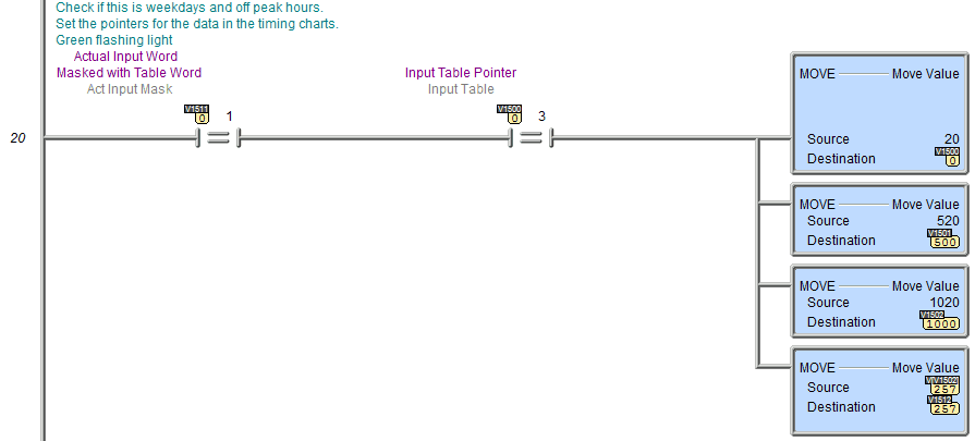
This is for the weekday peak times. 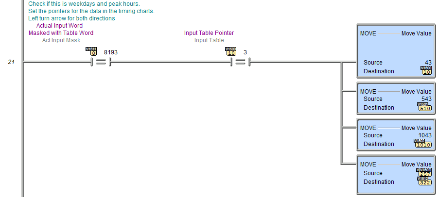
We now compare the actual inputs after the mask with the input table word. If they are equal, then move the output table word to the output channel and increment the pointers to the next step. 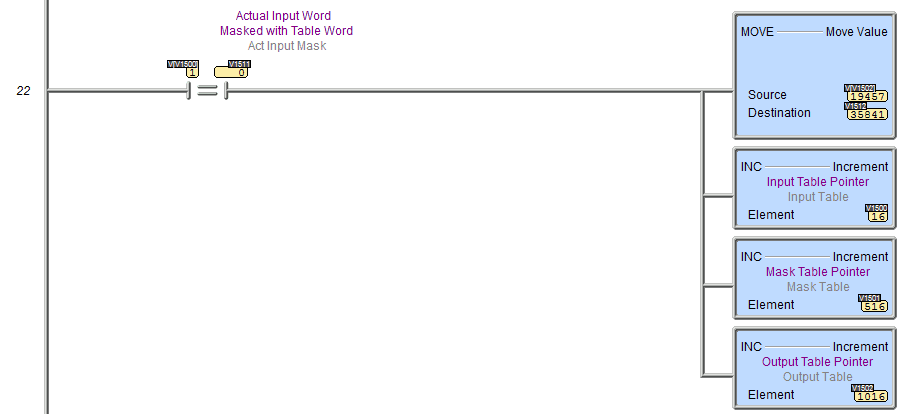
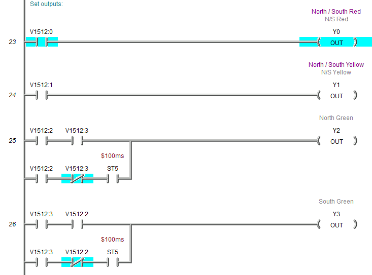
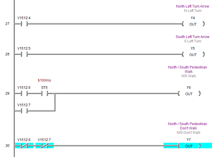
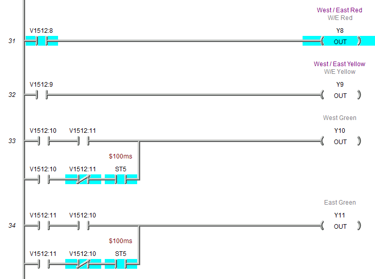
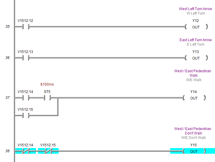
Outputs – Building a PLC Program – Traffic Light
The actual outputs are set using the output word bits. You will note that the flashing green lights are done when both green outputs are not on. This way will give me the most incredible flexibility when developing different sequences. The ‘do not walk signal’ is not part of the sequence but is controlled when the flashing walk or walk is not on.
The program will not change much for entirely different sequences.
This program and the data tables can be downloaded here. Note that to run this program, you must call up the Input, mask, and output tables and write them to the simulator or PLC.
Part 5 will make a Game of Simon by learning all about bit manipulation and sequencers.
Watch on YouTube: Building a PLC Program that You can be Proud Of – Ultimate Traffic Light Control
https://youtu.be/rkXNPVbYxX4.
If you have any questions or need further information, please get in touch with me.
Thank you,
Garry
If you’re like most of my readers, you’re committed to learning about technology. Numbering systems used in PLCs are not challenging to learn and understand. We will walk through the numbering systems used in PLCs. This includes Bits, Decimals, Hexadecimal, ASCII, and Floating Points.
To get this free article, subscribe to my free email newsletter.
Use the information to inform other people how numbering systems work. Sign up now.

The ‘Robust Data Logging for Free’ eBook is also available as a free download. The link is included when you subscribe to ACC Automation.