A flip-flop circuit in a PLC usually has one input and two outputs. When the input is activated, the two outputs alternately latch on/off opposite each other. It is used to toggle (latch) work on and off with just one input. In the PLC, it is a single input that will toggle an output on and off each time the input signal is activated.
Flip Flop Circuit using Relays.
Here is an example of a hard-wired flip-flop circuit using relays.
PLC Flip Flop Circuit Example
The PLC program will be a little different than the relays because of how the PLC scans. Scanning takes place from left to right, top to bottom. The output conditions from the logic are available to the next rung as the reason is solved. Outputs and inputs are usually read only once at the end of the scan. Remember to think of the outputs in the PLC as made before the break. This is the opposite of the relay logic presented above: break before make.
Let’s look at the logic. This is programmed using the Do-More Programming Software, which comes with a simulator. This complete programming package is free of charge and can be downloaded here.
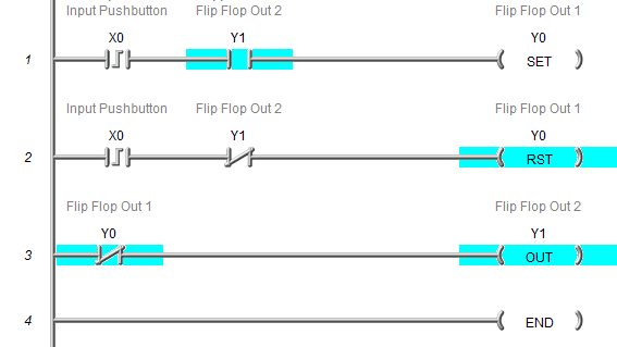
The input is on leading-edge instruction. (One Scan) If output 2 is on, then it will set output 1. If output 2 is not on, then it will reset output 1. The third line of code will determine the state of output two based on output 1.
You may be asking yourself why we do not just use the conditions from output 1 to control output 1. This is because if we substituted output 1 for the input conditions, output one would never turn on/off. The output conditions are available for the following line of the PLC code. This would allow the output to be set and reset within the scan without being updated. Using output 2 is the only way in which this logic would work.
Running the PLC Logic for the Flip-Flop Circuit
An automated picture shows the input toggling on / off and the outputs flip-flopping.

Note: An emergency condition can be added to the set or reset rungs to control the output either way automatically.
Watch on YouTube: Creating a Flip Flop Circuit in the PLC
If you have any questions or need further information, please get in touch with me.
Thank you,
Garry
If you’re like most of my readers, you’re committed to learning about technology. Numbering systems used in PLCs are not challenging to learn and understand. We will walk through the numbering systems used in PLCs. This includes Bits, Decimals, Hexadecimal, ASCII, and Floating Points.
To get this free article, subscribe to my free email newsletter.
Use the information to inform other people how numbering systems work. Sign up now.

The ‘Robust Data Logging for Free’ eBook is also available as a free download. The link is included when you subscribe to ACC Automation.