We will now establish communication using Modbus TCP from the C2-NRED module to the Ethernet ports of the BRX Do-More and Click PLCs. Previously, we installed version 5.31.0 of the node-red-modbus-contrib package. We utilized the C2-NRED Package Compatibility Finder to locate and download this Node-RED package.

Efficient PLC communication is essential for seamless operations. In this process, we will use the installed Modbus nodes to read 10 registers from the BRX Do-More PLC and write these values to the Click PLUS PLC. This will be done through the Ethernet port on the C2-NRED module. The C2-NRED Node-RED module is a versatile platform for integrating different systems and enhancing the overall efficiency of industrial setups. Let’s get started.
Our entire Click series can be found here.
All of the previous information for the Click PLC can be applied to the Click PLUS. We are currently focusing on the new C2-NRED Node-Red module for the Click PLUS PLC slot. Here is what we have covered so far:
Introductory Video:
Unlock Your Creativity with the Click PLUS PLC C2-NRED – The Gateway to Node-RED Innovation!
– What is the C2-NRED Module? Node-RED?
CLICK PLUS C2-NRED: Easy Install for PLC Module! – Video
– Updating firmware software in Click and C2-NRED
– Setting up IP addresses and starting the flow editor
Unleash Innovation: Node-RED Flow in Click PLC – Video
– First Node-RED flow program in the C2-NRED module. Full control.
The programming software and manuals can be downloaded from the Automation Direct website free of charge. Watch the video below to see how to control our inputs and outputs with both our C2-NRED module and Click PLUS PLC.
Master Node-Red C2-NRED Control of Click PLC I/O – Video
Control of PLC outputs via inputs is key in automation. Discover how the C2-NRED module and Click PLUS PLC enhance efficiency and precision!
Faster NODES Install with C2-NRED Node-RED! – Video
Installing nodes on the Click PLUS C2-NRED module (Node-RED 3.0, Node.js 14.1) is simple, but version compatibility must be considered.
Click PLC & AEDES MQTT: What is the Big Deal? – Video
CLICK PLC C2-NRED with Aedes MQTT Broker transforms automation communication by enabling MQTT without a server, enhancing speed and efficiency. Let’s dive in…
How to Use the Click PLC C2-NRED Package Finder – Video
Wondering if your Node-RED package works with the Click PLUS PLC C2-NRED module? Use the C2-NRED Package Compatibility Finder on GitHub to find compatible…
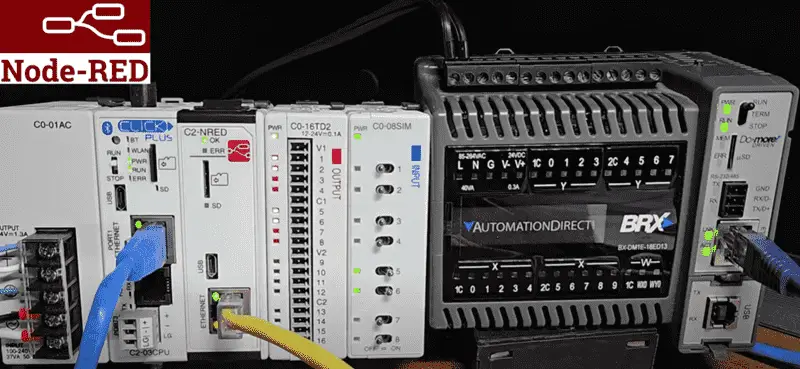
Setting up the BRX Do-More PLC
Setting up the BRX Do-More PLC is crucial in establishing a robust industrial automation system. The BRX Do-More PLC, known for its reliability and versatility, offers advanced features that cater to a wide range of automation projects. We have an entire series on the BRX Do-More PLC.
Configuring the BRX Do-More PLC involves setting up the Ethernet port with a fixed IP address and enabling the Modbus Server (Slave). Call up the system configuration in the Do-More Designer Programming Software.
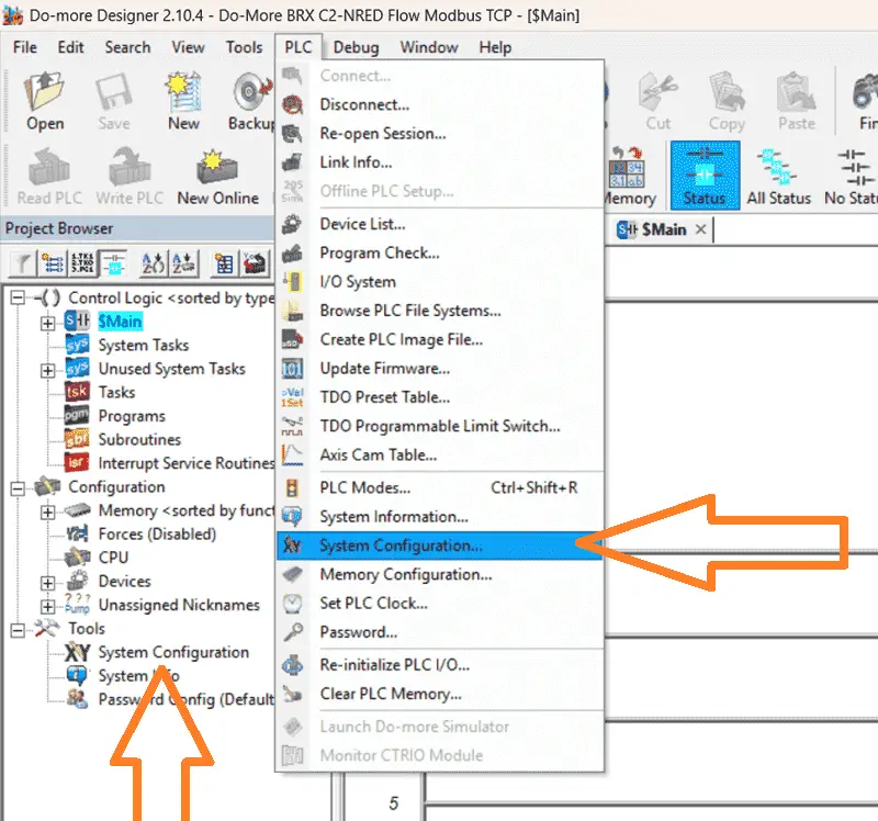
Select the system configuration under Tools in the project browser menu. This can also be selected from the main menu | PLC | System configuration… The system configuration window will be displayed.
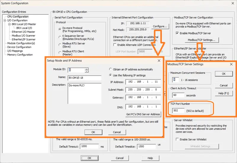
Under the CPU Configuration selection (Default), you will see the Internal Ethernet Port Configuration. This will show you the current IP address that has been assigned. Select Configure… This will allow us to set the static IP for our network. Select Close.
Under the Modbus/TCP Server Configuration on the same page, ensure that the Enable ModbusTCP Server is checked. We will leave all the default settings for the Modbus/TCP Settings window. Note that the port for Modbus TCP is 502. We will need this and the IP address for our next step.
Node-RED C2-NRED Modbus Flow
We will set up our Node-RED C2-NRED module for our Modbus TCP communication. Using the Click Programming Software, we have connected to our Click PLUS PLC and are viewing our previous ladder logic program where we installed the Modbus Nodes.
Call the C2-NRED Module Configuration window by selecting C2-NRED under the main menu | Setup | Slot0 Setting…
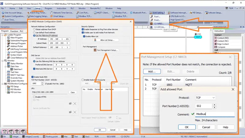
You will see the static IP address of our Node-RED module and the setup parameters we have discussed previously.
We can now select the Port Management Setup under the C2-NRED Module Configuration window. This will display the port management setup window. You will see our existing MQTT port. We can now add our port 502 for our Modbus TCP communication. Select OK to add our port for Modbus. Select OK to close the Port Management Setup Window. Finally, select OK to close the C2-NRED Module Configuration window.
Our port is now set for our Modbus TCP communication. Node-RED is a powerful tool for industrial automation, offering a seamless solution for Modbus communication. The Node-RED nodes and flows specific to Modbus TCP allow users to unlock a world of possibilities in PLC programming and data acquisition.
C2-NRED Modbus TCP Flow to Read BRX Do-More PLC
Open up our previous Flow using the Click programming software.
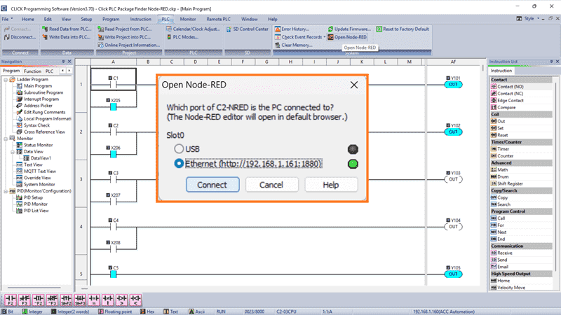
This can be done by selecting the PLC menu option on the Click programming software. Select Ethernet and then choose Connect.
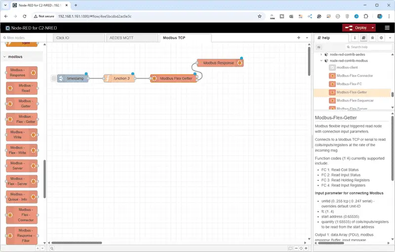
Your default browser will be displayed with the flow program we created last time.
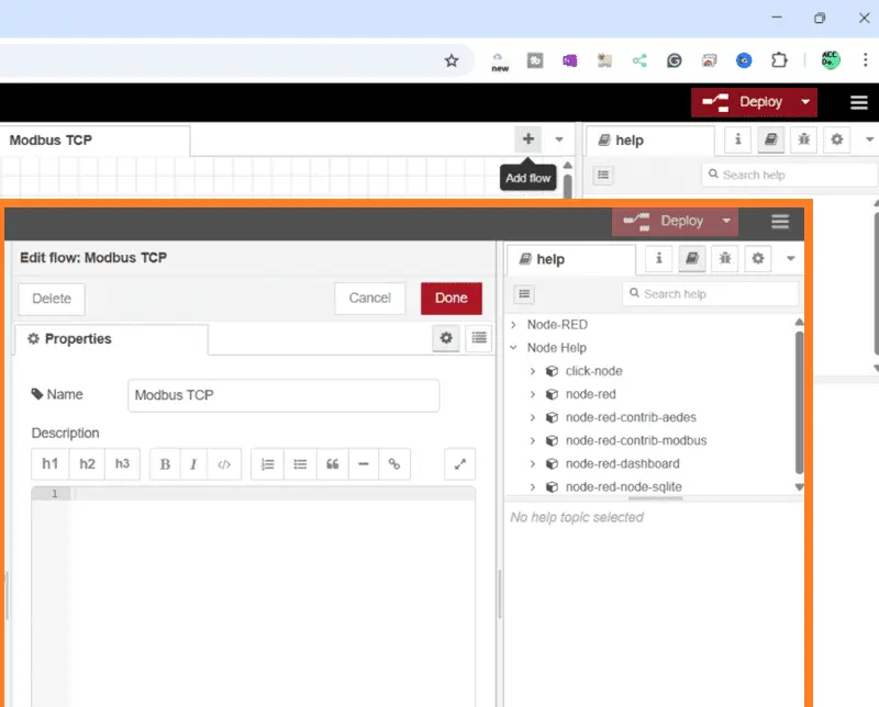
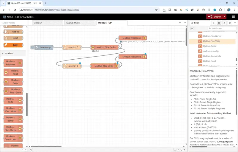
We will add a tab for a new flow for our Modbus communication. Select Add Flow and name the tab Modbus TCP. Select Done.
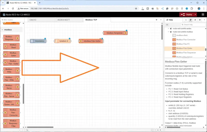
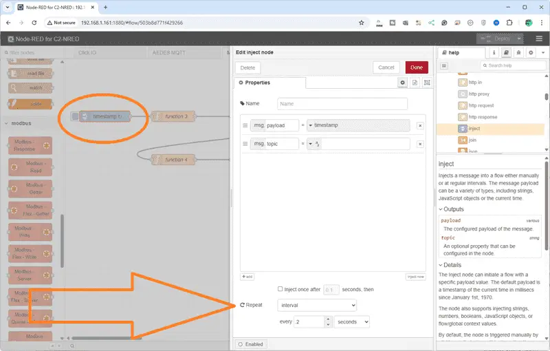
Add an inject function, Modbus Flex Getter, and Modbus Response nodes to the workspace.
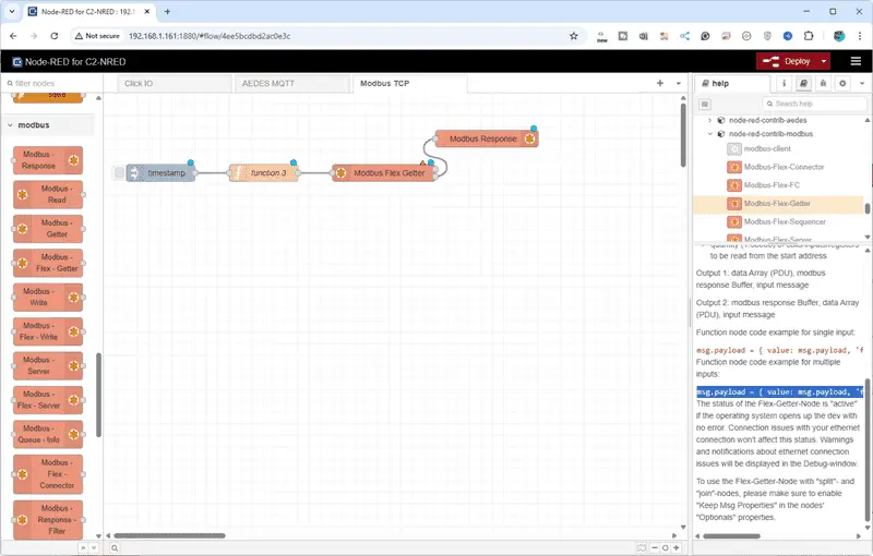
Connect the nodes together. In the help section for the Modbus-Flex-Getter, select the code example for multiple inputs. Right-click and copy this selection.
msg.payload = { value: msg.payload, 'fc': 3, 'unitid': 1, 'address': 0 , 'quantity': 10 } return msg;
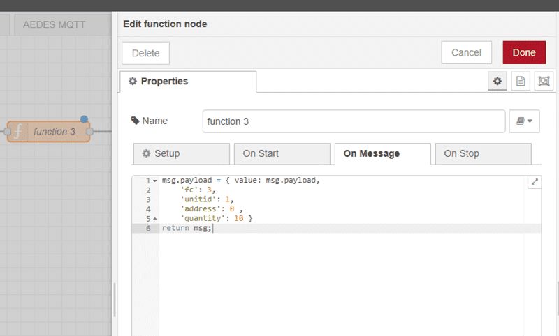
Double-click on the function node. Paste the code example into the On Message tab of the function node.
msg.payload = { value: msg.payload,
‘fc’: 3,
‘unitid’: 1,
‘address’: 0 ,
‘quantity’: 10 }
return msg;
We will separate the parameters to make it easier to read. The function code will be 3 to indicate we are reading holding registers. Unit ID will be one, which we are reading at address zero, and we will read 10 registers. Select Done.
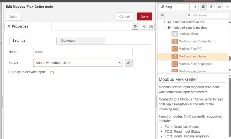
The red triangle on the Modbus-Flex-Getter node means we must set up this node or provide additional information. Double-click on the node. The red box indicates that we must add the Modbus client so it will know where to send the instructions that we have set in the function node. Add a new Modbus client.
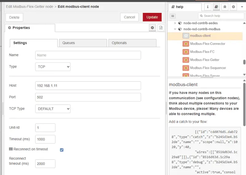
Our type will be TCP, and the host will be the address for the BRX Do-More PLC that we reviewed before. Our port will be set for 502, which is the default. All other settings will be left as their default. Select Add.

Our Modbus Flex Getter node is now set to communicate with our BRX D0More PLC. Select Done.
Select Deploy to write our program into the C2-NRED module and execute our Flow.
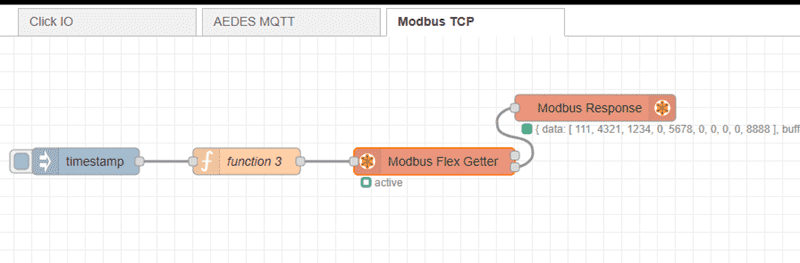
Select the inject (timestamp) node to test our Flow. You will see that the Modbus Response node will show the information returned from the BRX D0-More PLC under the array called Data.
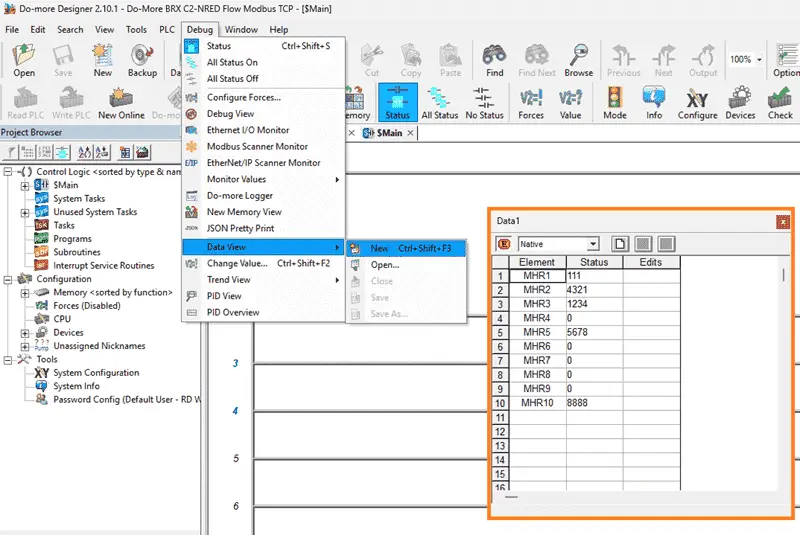
Using the Data View window in the Do-More Designer software, we can change and verify the registers that are being read. This test ensures that our Node-RED Flow is working as intended.
Setting up the Click PLUS PLC
Returning to our Click PLC programming software, call up the COM Port Setup window. Main menu | Setup | Com Port…

Select Port 1 in the COM Port Setup window. We will ensure that we configure this Click PLC Ethernet port with a fixed IP address. This will enable our Node-RED flow program to find this PLC on our network.
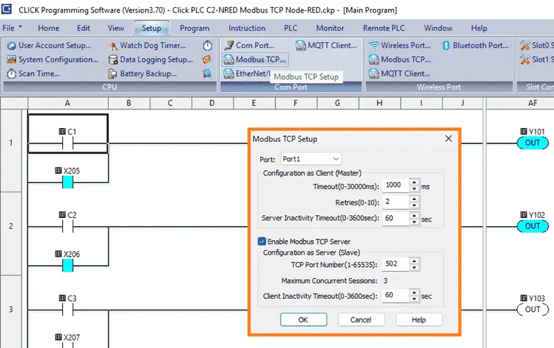
The default for the Modbus TCP Server is enabled in the Click programming software. We will verify this by selecting Modbus TCP… from the main menu | Setup. This is chosen in our case with the default port 502. Select OK.
The Click PLUS PLC, just like the BRX Do-More, is now set up as a Modbus Server (Slave) on our network. We can now read the information from the BRX Do-More and write this information into the Click PLUS PLC.
C2-NRED Modbus TCP Flow to Write to Click PLUS PLC
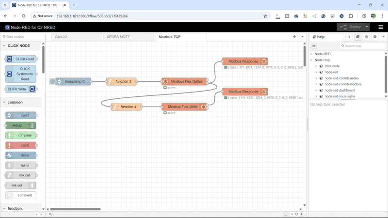
Returning to our flow program, add a function, Modbus Flex Write, and another Modbus Response node. Join the Modbus Flex Getter node to the new function node, then the function node to the Modbus Flex Write. Then join the Modbus Flex Write to the Modbus Response node.
Under the help file for the Modbus Flex Write, copy the multiple write example.
msg.payload = { value: msg.payload, 'fc': 15, 'unitid': 1, 'address': 0 , 'quantity': 10 } return msg
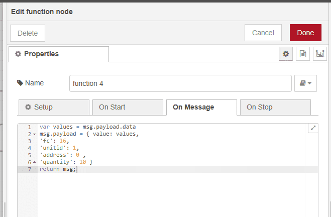
Paste this in the new function node under the On Message tab. We will separate the parameters to make it easier to read.
var values = msg.payload.data
msg.payload = { value: values,
‘fc’: 16,
‘unitid’: 1,
‘address’: 0 ,
‘quantity’: 10 }
return msg;
The function code will be 16 to indicate we are writing holding registers. Unit ID will be one, which we are writing at address zero, and we will write 10 registers. Select Done.
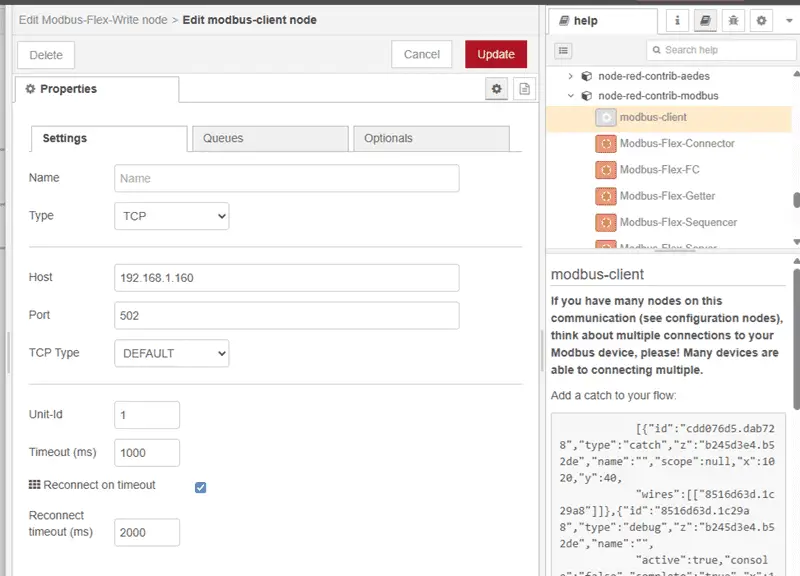
The red triangle on the Modbus-Flex-Write node means we must set up this node or provide additional information. Double-click on the node. The red box indicates that we must add the Modbus client so it will know where to send the instructions that we have set in the function node. Add a new Modbus client.
Our type will be TCP, and the host will be the address for the Click PLUS PLC that we just reviewed. Our port will be set for 502, which is the default. All other settings will be left as their default. Select Add.
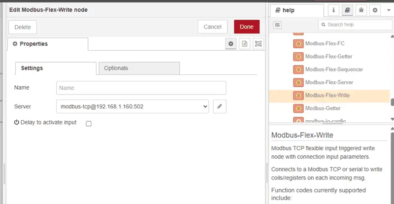
Our Modbus Flex Write node is now set to communicate with our Click PLUS PLC. Select Done.
Select Deploy to write our program into the C2-NRED module and execute our Flow. Verify using the Modbus Response nodes that everything is working as expected.

The Modbus Response node will show the information returned from the BRX D0-More PLC under the Data array. The Modbus Response node for the Modbus write will show this same data written.
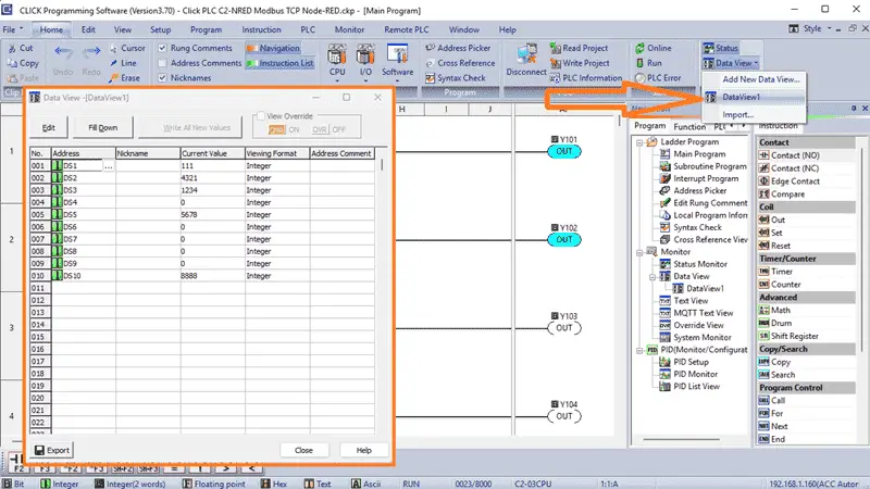
Using the Data View window in the Click PLC programming software, we can monitor the registers that are being written. This ensures that our Node-RED Flow is working as intended.
With the potential of Click PLC in conjunction with C2-NRED, you can optimize data acquisition, streamline communication, and elevate the efficiency of your automation projects. This integration simplifies the connection process and enhances industrial automation systems’ overall performance and reliability, making it a valuable asset in PLC communication and automation projects.
To review how we found and installed the Modbus Nodes with the recommended version, click here. Click here to learn more about the Click PLUS PLC.
Download the Click PLUS PLC, BRX PLC Programs, and Flow here.
Our Node-RED series can be found here.
Watch on YouTube: Master the Click PLC C2-NRED Package Compatibility Finder!
Click PLUS PLC C2-NRED Module
C2-NRED Applications Guide
https://cdn.automationdirect.com/static/manuals/c2appguide/c2appguide.pdf
C2-NRED Package Compatibility Finder
https://automationdirect.github.io/CLICK-PLC/Node-RED/C2-NREDModuleVersionCheck/CompatibiltyCheck.html
Aedes Broker – Node-RED
https://flows.nodered.org/node/node-red-contrib-aedes
CLICK PLUS Hardware User Manual (C2-USER-M) chapter 5
https://cdn.automationdirect.com/static/manuals/c2userm/ch5.pdf
Node-RED Links
Node-RED Organization Home Page
Getting Started – Run Locally
Node-RED running on Windows (Run at Startup)
Securing Node-RED
Node-RED Essentials Videos (Basics of the Editor)
Learn JavaScript Free
w3schools JavaScript Tutorial
learn-js.org
Node-Red JavaScript Primer
Our entire series on the Click PLC can be found here.
The Click PLC can be programmed using free Click programming software from Automation Direct.
Here is a link to the software. Version 3.70
The entire Click PLC series before the Click PLUS release can be found here.
All previous posts and information are still valid with the Click PLC lineup.
YouTube Click Playlist
YouTube Click PLUS Playlist
Click and Click PLUS PLC Overview
Click and Click PLUS PLC Videos from Automation Direct
If you have any questions or require additional information, please do not hesitate to contact me.
Thank you,
Garry
If you’re like most of my readers, you’re committed to learning about technology. The numbering systems used in PLCs are not challenging to know and understand. We will walk through them, including Bits, Decimal, Hexadecimal, ASCII, and Floating Point.
To get this free article, subscribe to my free email newsletter.
Use the information to inform other people how numbering systems work.
Sign up now.

The ‘Robust Data Logging for Free’ eBook is also available as a free download. The link is included when you subscribe to ACC Automation.