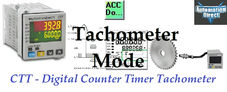
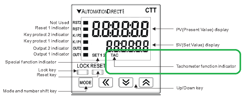
The CTT series from Automation Direct are multi-function digital units. They incorporate a multi-function digital counter, timer and tachometer all within the same unit. Tachometer mode will bring in pulses that can be from a sensor, incremental encoder, etc. and convert this to a rate. Rates such as speed or frequency deal with units per time. The CTT makes converting and using these pulses easy. The tachometer mode has four different output settings; 2Lo1Lo, 2Lo1Hi, 2Hi1Lo and 2Hi1Hi.
We will be reviewing the tachometer mode of the CTT and programming a rate based on the frequency of a relay output of a PLC. Let’s get started.
Previously in this CTT Series – Counter / Timer / Tachometer we have discussed;
– CTT Counter Timer Tachometer – Getting Started
o Un-boxing the CTT Video
o Powering up the Unit Video
– CTT Timer Modes
o Signal On Delay 1 Timer
o Signal On Delay 2 Timer
o Signal Off Delay Timer
o Signal On Timer
o Power On Delay Timer
o Power On Delay Hold Timer
o Repeat Cycle Timer
o Repeat Cycle Hold Timer
o Repeat Cycle 2 Timer
o Signal Cumulate Timer
o Signal Twin On Start Timer
o Signal Twin Off Start Timer
– CTT Counter Modes
o Stage 1 Counting
o Stage 2 Counting
o Batch Counting
o Total Counting
o Dual Counting
– Counter Timer Mixed Modes
o Signal On Delay 1 Up
o Signal On Delay 2 Up
o Signal Off Delay Up
o Signal On Up
o Power On Delay Up
o Power On Delay Hold Up
o Repeat Cycle Up
o Repeat Cycle Hold Up
The manual is broken up into chapters for each of the operation modes of the CTT. (Counter, Timer, Timer + Counter, Tachometer)
Once we find our operation mode, you look for the timing chart mode for your application. The manual includes all of the information that you need for that mode. This includes wiring diagrams, timing charts, program steps and dip switch settings.
The tachometer mode only has four pages of information to set up this unit.
CTT – Tachometer Output Modes
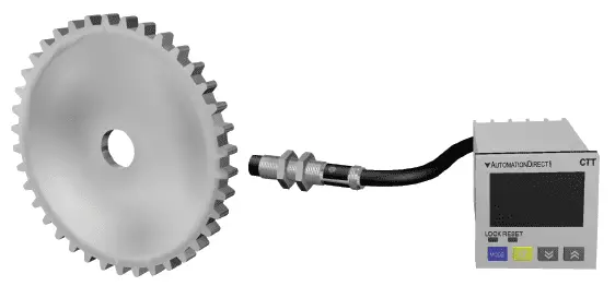
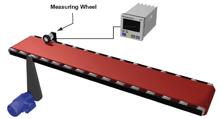
As mentioned above we are measuring input pulses over time. An example would be Meters per minute, Kilometers per hour, rate per second (frequency), etc.
The CTT has two outputs that we can control in the following four different ways.
2Lo1Lo
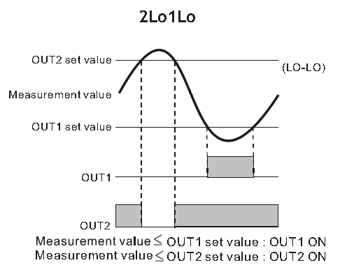
When the measured present value PV is less than or equal to the set value SV1 Output 1will turn ON. When the measured PV is greater than SV1 Output 1 will turn OFF.
When the measured present value PV is less than or equal to the set value SV2 Output 2 will turn ON. When the measured PV is greater than SV2 Output 2 will turn OFF.
In the video below we will be using this output setting.
2Lo1Hi
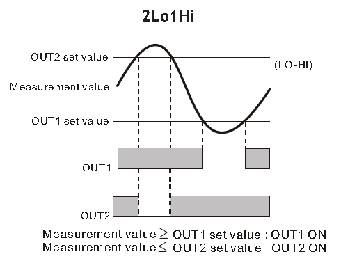
When the measured present value PV is greater than or equal to the set value SV1 Output 1 will turn ON. When the measured PV is less than SV1 Output 1 will turn OFF.
When the measured present value PV is less than or equal to the set value SV2 Output 2 will turn ON. When the measured PV is greater than SV2 Output 2 will turn OFF.
2Hi1Lo
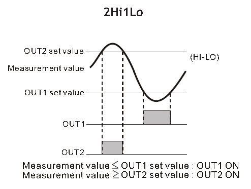
When the measured present value PV is less than or equal to the set value SV1 Output 1will turn ON. When the measured PV is greater than SV1 Output 1 will turn OFF.
When the measured present value PV is greater than or equal to the set value SV2 Output 2 will turn ON. When the measured PV is less than SV2 Output 2 will turn OFF.
2Hi1Hi
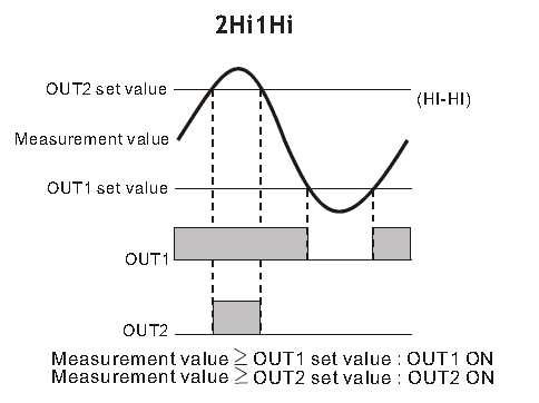
When the measured present value PV is greater than or equal to the set value SV1 Output 1 will turn ON. When the measured PV is less than SV1 Output 1 will turn OFF.
When the measured present value PV is greater than or equal to the set value SV2 Output 2 will turn ON. When the measured PV is less than SV2 Output 2 will turn OFF.
CTT – Counting Speed – Tachometer Mode
Our selection for counting speeds includes; 10,000 counts per second (cps), 5000 cps, 1000 cps, 200 cps, 30 cps and 1 cps. We find the maximum count frequency we need for our application and select the appropriate speed. In our video example below we are using a mechanical relay from a PLC. Our maximum speed will be 10 counts per second. We will set our speed to 30 cps. Selecting the maximum counting speed will result in false signals being picked up by the unit due to the bounce of the mechanical relay.
Here is a link to describe contact bounce and de-bouncing.
http://www.elexp.com/Images/Contact_bounce_and_De-Bouncing.pdf
Scaling the CTT – Tachometer Mode
We use this to convert the displayed PV into engineering unit, such as RPM, inches, millimeters, feet per minute etc. A decimal point and scaling with a range from 0.001 to 99.999 can be selected. Our example will be frequency of pulses, so we will leave this as the default of 1.000 with no decimal place.
Delay Time Power On
We can set up the delay time after switching on the power: 0.0 (default). The tachometer will start to run when the set delay time is due after the power is switched on. Setup range: 0.1 to 99.9 seconds. We will leave this as the default.
Input Filter
Since we are measuring pulses over time, the rate may not be very stable close to our set points. Missing one pulse in the time period may cause the output to turn on and then off in the next time period when the one pulse is seen again. We can set up an input filter to average the values. The average value is for making the present value detected by the tachometer more stable. The setup range is 0 to 3 (1 = 2 data, 2 = 4 data, 3 = 8 data). For example, if you select “3”, the system will average the 8 present values from the tachometer to make the present value displayed on the screen more stable.
Watch on YouTube: CTT Counter Timer Tachometer – Tachometer Mode
Summary of CTT features
– Can operate as a digital counter, timer, combination timer + counter or tachometer
– Accepts voltage and non-voltage inputs from a wide variety of NPN, PNP, or dry contact sensors
– Selectable counting speeds from 1 to 10,000 cycles per second
– Multiple transistor and relay outputs can operate as momentary or maintained
– Double-line, 6-digit, 2-color LCD display
– Easy configuration with externally accessible DIP switches or the lockable keypad
– Display decimal point selection
– Available in 100-240VAC and 24VDC powered models
– UL508 listed (E311366), cULus, CE marked
Counter, Timer, Tachometer – CTT Series from Automation Direct
Shop Multi-Function Digital Counter / Timer / Tachometer
CTT Overview
https://cdn.automationdirect.com/static/specs/cttcountertimertachoverview.pdf
CTT Quick Start Guide
https://cdn.automationdirect.com/static/manuals/cttqsg/cttseries_qsg.pdf
Digital CTT Manual
https://cdn.automationdirect.com/static/manuals/digitalctt/digitalctt.html
Rhino Power Supply
https://www.automationdirect.com/adc/Overview/Catalog/Power_Products_(Electrical)/DC_Power_Supplies
https://cdn.automationdirect.com/static/specs/pslpowersupplies.pdf
This concludes our series on the CTT – Counter, Timer, and Tachometer.
If you have any questions or need further information please contact me.
Thank you,
Garry
If you’re like most of my readers, you’re committed to learning about technology. Numbering systems used in PLC’s are not difficult to learn and understand. We will walk through the numbering systems used in PLCs. This includes Bits, Decimal, Hexadecimal, ASCII and Floating Point.
To get this free article, subscribe to my free email newsletter.
Use the information to inform other people how numbering systems work. Sign up now.

The ‘Robust Data Logging for Free’ eBook is also available as a free download. The link is included when you subscribe to ACC Automation.