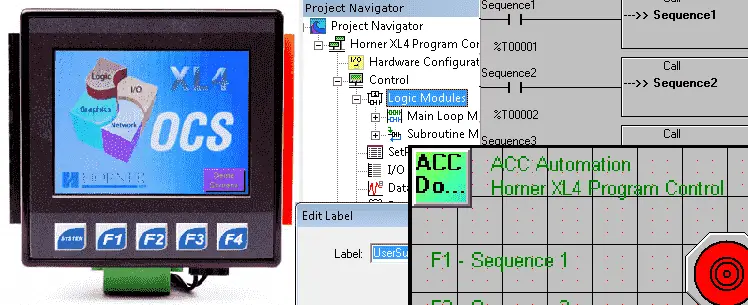
We will now look at program control in the Horner XL4 all in one controller. PLC programs scan usually from left to right, top to bottom. The outputs from the previous rung are available for the next. This is the operation of a PLC. Program control instructions allow us to add or remove parts of our program during each scan of the controller. The Horner APG XL4 has subroutines which we can achieve this control. We will look at how to divide your main logic up and at how subroutines work.
Previously we discussed the following in our Horner XL4 Series:
System Hardware
Installing the Software Cscape
Cscape Software Setup
Establishing Communication
Numbering System and Addressing
User Interface
Timers and Counters
Compare and Move Instructions
Math Instructions
Understanding how the PLC will scan and update your program is critical in programming and troubleshooting your system. The following post will review the PLC program scan. https://accautomation.ca/understanding-the-plc-program-scan/
Main Loop Modules – Horner XL4 Program Control
Cscape allows us to split up our Main Loop Modules into small code sections so it is easy to read. All of our programs will consist of at least one Main Loop Modules.
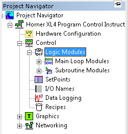
These modules will solve logic every scan based on the sequence that we specify. To add another module right-click the Main Loop Modules in the Project Navigator and select New Enhanced Ladder Logic Block.
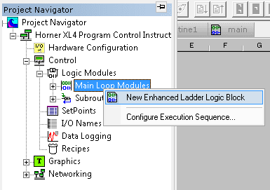
Alternatively, we can also go to the main menu – Program | New Enhanced Ladder Logic Block
You will also see that we can Configure the Execution Sequence…
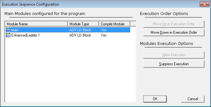
This will allow us to change the execution order of the modules, and determine if we want to suppress (stop) the execution of any module.
Call Element – Horner XL4 Program Control
Use the Call element to call a subroutine. If the condition in front of the Call element is true then the subroutine will be executed. Execution begins with the label of the subroutine and ends when the Return element is reached. After the Return element, the line after the Call element is scanned.
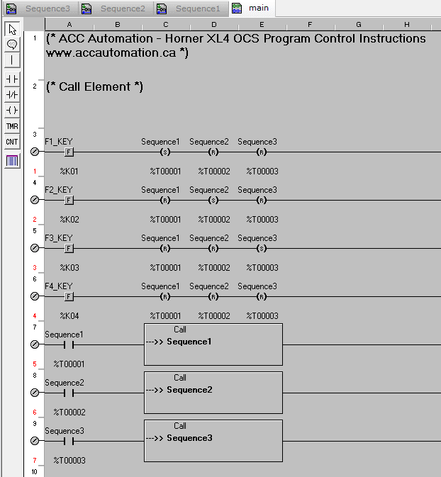
Here is a Call element in a PLC ladder logic diagram example.
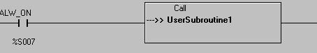
You will notice the conditional input in front of the Call element. In our case, it is the system bit for always on. This means that the subroutine will be called (executed) every scan.
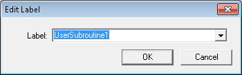
When you double click on the Call element the above Edit Label window will pop up. You can now enter the subroutine name or select from a list using the down arrow to the right of the window.
Subroutine – Horner XL4 Program Control
The subroutine uses a label that must have a unique name. A Return element is the last rung of the subroutine and returns control to the line after the Call instruction. Subroutines can be nested up to eight levels. This means that a subroutine can call another subroutine, which calls another subroutine, etc. up to eight times.
Note: Nested subroutines are hard to read unless significant documentation is present with the program.
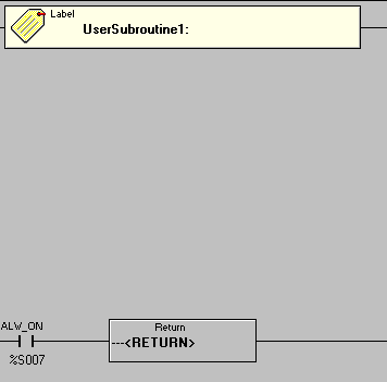
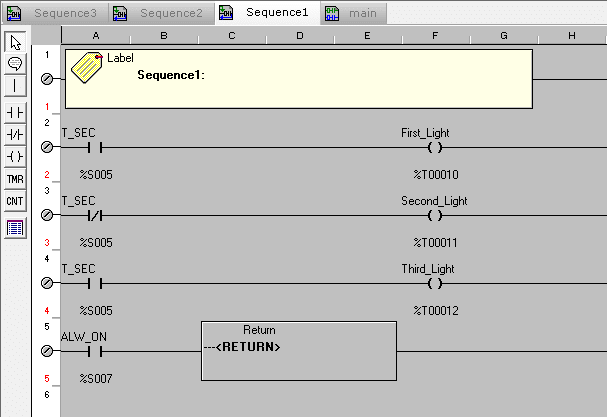
The above picture shows the label and return elements of the subroutine in a PLC ladder logic diagram example.
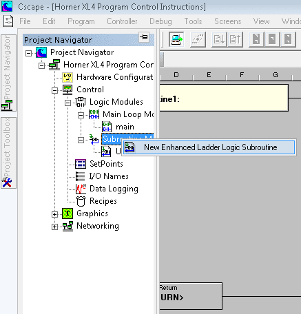
We can add new subroutines in a couple of different ways. Calling up the Project Navigator and right-clicking on the Subroutine Modules will allow you to select New Enhanced Ladder Logic Subroutine.
The second way is to select the program in the main menu and then select New Enhanced Ladder Logic Subroutine.
Let’s look at an example. We will have three subroutines and they will be called up by the first three function keys on our display. Each of the three sequences will control the lights on our display differently.
Here is the main program in a PLC ladder logic diagram example.
Sequence 1 program in a PLC ladder logic diagram example
Sequence 2 program in a PLC ladder logic diagram example

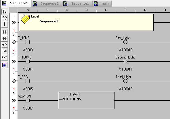
Sequence 3 program in a PLC ladder logic diagram example
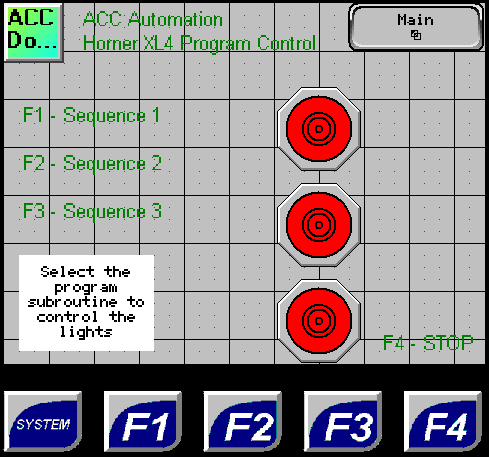
Here is the Horner APG HMI screen sample with the three lights.
See this logic in action by watching the YouTube video below.
You can download this application here. It will contain all of the screens and logic programming.
All of the documentation for the XL4 can be downloaded at the following URL:
https://hornerautomation.eu/product/xl4-prime-ocs-3-5-colour-touchscreen/
Next time we will look at rotating and shift register instructions.
Watch on YouTube: Horner XL4 Program Control Instructions
If you have any questions or need further information please contact me.
Thank you,
Garry
If you’re like most of my readers, you’re committed to learning about technology. Numbering systems used in PLCs are not difficult to learn and understand. We will walk through the numbering systems used in PLCs. This includes Bits, Decimal, Hexadecimal, ASCII, and Floating Point.
To get this free article, subscribe to my free email newsletter.
Use the information to inform other people how numbering systems work. Sign up now.

The ‘Robust Data Logging for Free’ eBook is also available as a free download. The link is included when you subscribe to ACC Automation.