The hostlink communication protocol is a method developed by Omron for communication to PLCs and other equipment. This ASCII-based protocol is used over RS232 or RS422/RS485. It is a many-to-one implementation, meaning you can communicate with up to 32 devices back to a master. (1: N) This communication on the industrial floor can control PLCs, Temperature Controllers, Panel Meters, etc.
Our look at this protocol will include the wiring, setting of RS232 port settings, protocol format, and writing a VB6 program to read information from the PLC. I will also point you to links to store this information in a database and share it over an intranet/internet. Let’s get started.
Wiring Serial Port – Omron PLC Host Link Protocol
The wiring of the communication ports will depend on the equipment purchased. It will depend on your implementation and electrical noise in the plant. If communicating over 15 meters, switching to an RS422 or RS485 connection is recommended. However, I have seen RS232 runs of 50 meters without an issue.
The above diagram is the basic communication needed for RS232C. Note that the shield of the communication wire is connected only to one side. This ensures that any noise in the transmission is filtered to one end.
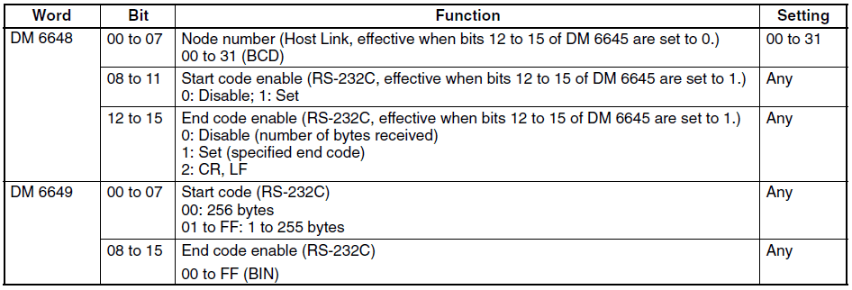
Serial Settings – Omron PLC Host Link Protocol
Settings for RS232C communications are set in several ways. Current Omron SMR1/CPM1 PLCs are set through data memory locations. Older Omron C**K PLC was established through a series of dip switches.
Note: You must often cycle the power or switch to program/run mode to activate the setting.
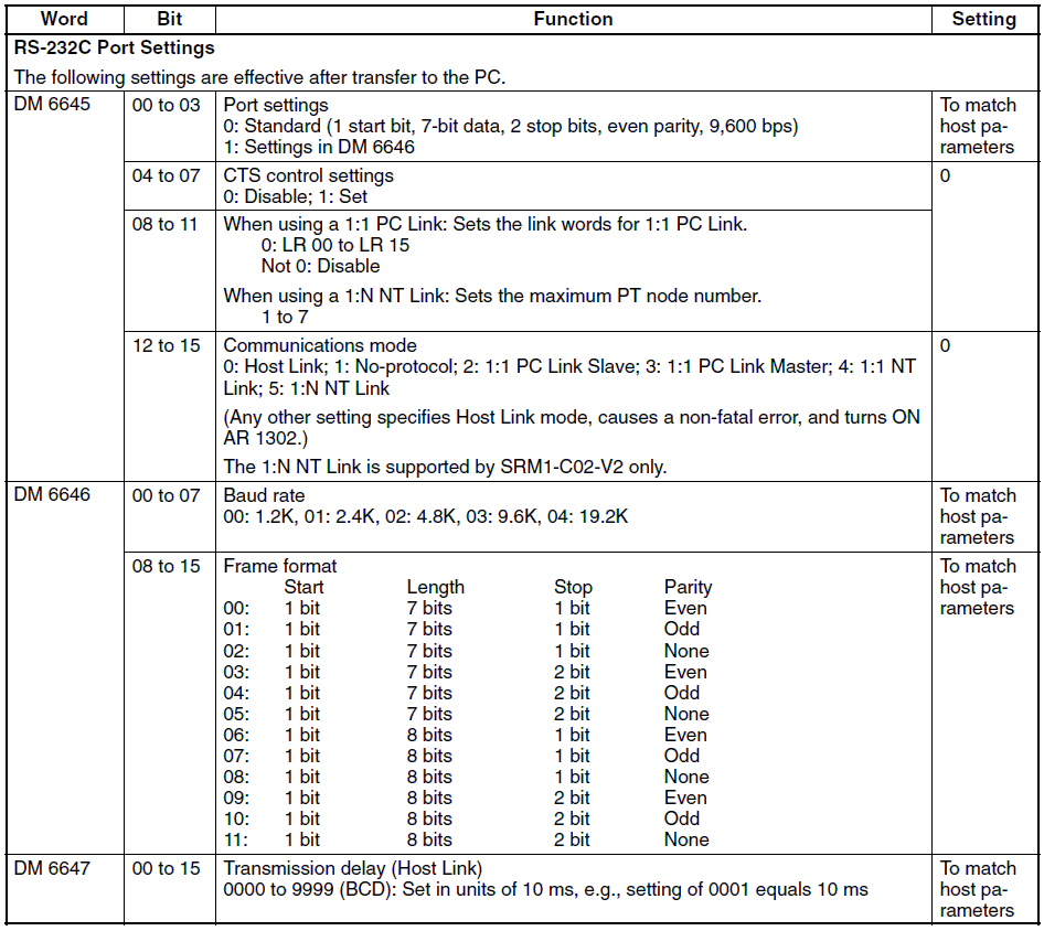
I generally leave everything at the default settings: 9600 bps, Even parity, 7 data bits, and one stop bit. The default host link unit number is 00. (32 max. – 00 – 31)
Protocol Format – Omron PLC Host Link Protocol
Each piece of equipment will have a list of parameters that can be read and written using the HostLink protocol. This can be found in the programming manual of the device. Here are the areas in the CPM1/CPM1A/CPM2A/CPM2C/SRM1(-V2) from the programming manual.
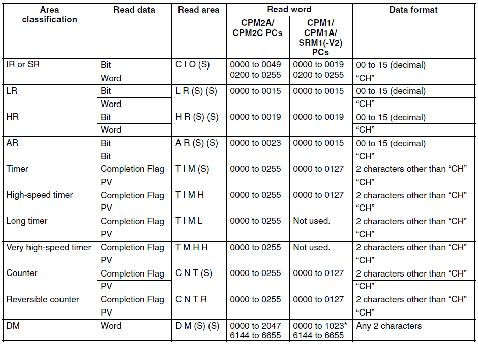
Let’s take a look at the command to read the DM area. All of the commands and responses will be in an ASCII format.
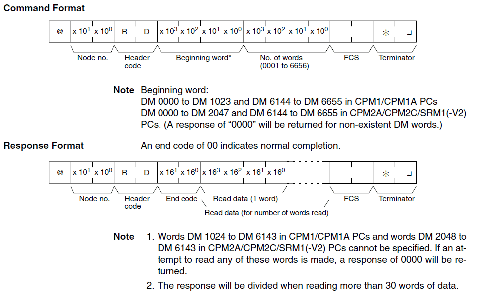
The command format begins with a ‘@‘ sign followed by the Node / Unit number you wish to communicate. The header code is the command which you want to execute. (RD) This header code will determine the next series of information. In our case, the next four digits will be the beginning word, followed by the next four digits to indicate the number of words. The next part of the command is the FCS (checksum) calculation. Comparing this at each end will ensure that the command/response is correct. FCS is 8-bit data converted into two ASCII characters. The 8 bits result from an Exclusive OR performed on the data from the beginning to the end of the text in the frame. In our case, this would be performed on the following:
"@00RD00000010"
The last part of the command is the terminator. This is an ‘*’ followed by the character for the carriage return. (CHR$(13))
The response format begins with a ‘@’ sign followed by the Node / Unit number you are communicating with. The header code is next (RD), followed by the End Code. The end code is a two-digit ASCII code that indicates the message response/errors when executing the action. A normal code of ’00’ means that everything is fine. See the operation manual for the entire list of end codes for your equipment. The next part of the response depends on the header code executed. In our case, it would contain the data requested. The last two parts of the response are the FCS and terminator, just like the command format.
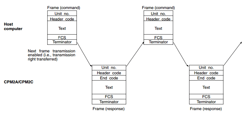
The above shows the timing of the command and responses.
Visual Basic VB6 (Example) – Omron PLC Host Link Protocol
Now let’s look at an example of reading the first ten words from the DM area of an Omron PLC.
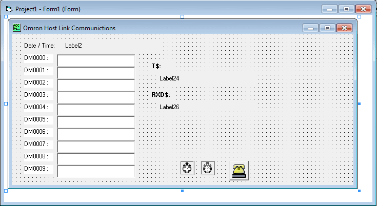
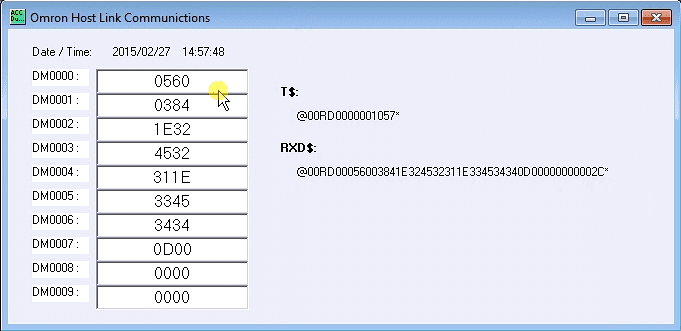
The first step is the design the form. You can see that we have our ten DM area words set out to populate with values. We also have a T$ for transmitting. This will show what we are sending to the PLC. The RXD$ will show what the response will be from the PLC.
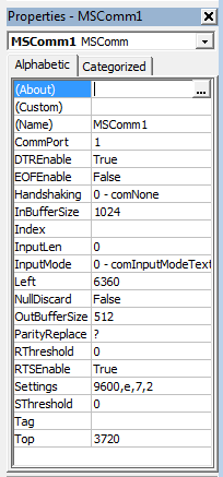
The MSComm is used to communicate through the serial ports of the computer. The following are the settings for the communication port.
Here is the VB6 code for the program:
When the form loads, the Date/Time will get updated, and Timer1 will be enabled. This timer controls the interval in which the commands get executed. (Set to 1 second)
Private Sub Form_Load()
 Label2.Caption = Format(Date, "YYYY/MM/DD") + "    " + Format(Time, "HH:MM:SS")
 Timer1.Enabled = True
 End Sub
The following code will open the communication port, set the command format, send the command through the port, receive the response through the port, and display the information. It will then close the communication port.
Private Sub Timer1_Timer()
 Timer1.Enabled = False
 MSComm1.PortOpen = True
 Label2.Caption = Format(Date, "YYYY/MM/DD") + "    " + Format(Time, "HH:MM:SS")
'Check DM AREA DM0000 to DM0009 data update
 T$ = "@00RD00000010"
 charreturn = 51
 GoSub FCS
 GoSub communicate
'Show Transmit information
 Label24.Caption = Buffer
 'Show Returned information
 Label26.Caption = rxd$
If Mid(rxd$, 6, 2) = "00" And (Len(rxd$)) >= charreturn Then
 Label4.Caption = Mid(rxd$, 8, 4)
 Label6.Caption = Mid(rxd$, 12, 4)
 Label8.Caption = Mid(rxd$, 16, 4)
 Label10.Caption = Mid(rxd$, 20, 4)
 Label12.Caption = Mid(rxd$, 24, 4)
 Label14.Caption = Mid(rxd$, 28, 4)
 Label16.Caption = Mid(rxd$, 32, 4)
 Label18.Caption = Mid(rxd$, 36, 4)
 Label20.Caption = Mid(rxd$, 40, 4)
 Label22.Caption = Mid(rxd$, 44, 4)
 End If
 Timer1.Enabled = True
 MSComm1.PortOpen = False
 Exit Sub
The following is the subroutine to communicate. Timer 2 is the time to wait before expecting an answer from the communication port. Once the command has been sent, a maximum of two seconds waiting for a response. If there is no response, nothing is returned. When the response is obtained, the FCS is checked, and the information is returned if correct.
communicate:
 rxd$ = ""
 Buffer = T$ + FCS$ + "*" + Chr$(13)
 MSComm1.Output = Buffer
 Timer2.Enabled = True
 Do
 DoEvents
 Loop Until Timer2.Enabled = False
 If Time > #11:59:50 PM# Then
 timeout = #12:00:02 AM#
 Else
 timeout = DateAdd("s", 2, Time)
 End If
 MSComm1.InputLen = 0
 Do
 If timeout <= Time Then GoTo timeoutcom
 DoEvents
 Loop Until MSComm1.InBufferCount >= charreturn
 rxd$ = MSComm1.Input
 fcs_rxd$ = Left((Right(rxd$, 4)), 2)
 If Left(rxd$, 1) = "@" Then
 T$ = Mid(rxd$, 1, (Len(rxd$) - 4))
 ElseIf Mid(rxd$, 2, 1) = "@" Then
 T$ = Mid(rxd$, 2, (Len(rxd$) - 5))
 rxd$ = Mid(rxd$, 2, (Len(rxd$) - 1))
 End If
 GoSub FCS
 If FCS <> fcs_rxd$ Then
 rxd$ = ""
 End If
 clearbuffer$ = MSComm1.Input
 Return
This is the FCS (checksum) calculation routine.
FCS:
 L = Len(T$)
 A = 0
 For J = 1 To L
 TJ$ = Mid$(T$, J, 1)
 A = Asc(TJ$) Xor A
 Next J
 FCS$ = Hex$(A)
 If Len(FCS$) = 1 Then FCS$ = "0" + FCS$
 Return
This routine will execute if the response is not received within the expected period.
timeoutcom:
 clearbuffer$ = MSComm1.Input
 rxd$ = ""
 Return
End Sub
Timer2 was delayed before looking for a response after sending the command.
Private Sub Timer2_Timer()
 Timer2.Enabled = False
 End Sub
Here is the code running – Omron PLC Host Link Protocol
Helpful Tips/Links:
– When troubleshooting serial communications, it is sometimes helpful to use HyperTerminal. This program will send and receive information in/out of the serial ports.
– HostLink Command Generator
– HostLink Command Format
Watch on YouTube: How to Implement the Omron PLC Host Link Protocol
If you have any questions, need further information, or would like a copy of this program, please get in touch with me.
Thank you,
Garry
If you’re like most of my readers, you’re committed to learning about technology. Numbering systems used in PLCs are not challenging to learn and understand. We will walk through the numbering systems used in PLCs. This includes Bits, Decimals, Hexadecimal, ASCII, and Floating Points.
To get this free article, subscribe to my free email newsletter.
Use the information to inform other people how numbering systems work. Sign up now.

The ‘Robust Data Logging for Free’ eBook is also available as a free download. The link is included when you subscribe to ACC Automation.