DIY PLC Training Lab: Lessons from 30 Years of Teaching
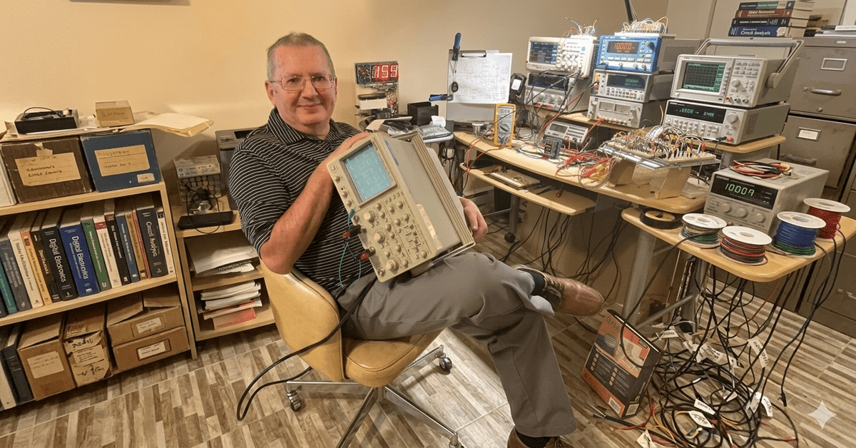
ACC Automation is growing — and part of that growth is bringing in voices from outside my own experience. I want to introduce you to Chris Urban, an automation educator and PLC trainer based near Montreal, Quebec, who has been teaching technicians and engineers for over 30 years. Chris reached out after finding the ACC PLC Simulator, and … Read more