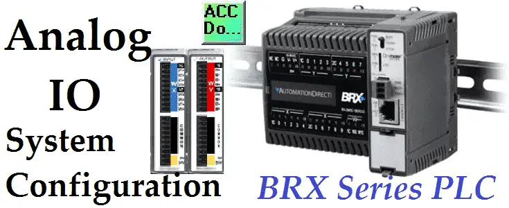
We will now configure and operate Analog inputs and outputs on our BRX Do-More controller. One of the features of the BRX Series PLC is the ability to expand its capability to fit your application. This is easily done by “snap-on” modules that will fit on the side of the BRX MPU (Multi-Processor Unit). As we have seen before in the BRX PLC System Configuration post we can add additional discrete inputs and outputs. Automation Direct now offers Analog Voltage and Analog Current input and output modules. These modules come as an 8 point channel unit. There is also a 4 point thermocouple input module also available. We will be configuring, scaling and programming the Analog input and output Voltage modules for our BRX PLC. Let’s get started. Continue Reading!
Tag Archives: Communications Protocol
BRX Do-More PLC AdvancedHMI – Modbus TCP
Modbus TCP will be used to connect AdvancedHMI to our BRX Do-More controller using Ethernet. Advanced HMI is a powerful, adaptable HMI/SCADA (Supervisory Control and Data Acquisition) development package that takes advantage of Visual Studio. There is no coding required and you can simply drag and drop items onto the page. The best thing is that the software is free. We will look at using AdvancedHMI with the BRX Do-More Series PLC.
Our sample BRX Do-More PLC program will display a digital panel meter and a gauge of a value in the PLC. Stop and start momentary pushbuttons on the HMI will allow this number to increase or stop. An indication will turn green when the number is increasing and red when it has stopped. The AdvancedHMI package will communicate Modbus TCP over Ethernet to the BRX Do-More PLC. We will be able to monitor our process via the AdvancedHMI window. Let’s get started. Watch on YouTube…
Continue Reading!
How to Implement Modbus TCP Protocol VBA Excel
We will use Visual Basic for Applications (VBA) to communicate to a PLC using Modbus TCP protocol. Reading ten registers in the PLC and displaying a bar graph in Excel. Previously we have used VB6 to communicate Modbus TCP.
Sequence for Modbus TCP on Excel using VBA
The following steps will be done:
- Explain Modbus TCP protocol
- Install OstroSoft Winsock Component
– Winsock API Calls for communication on network - Develop the Excel and VBA application
(Microsoft Excel 2010) - Communicate to the PLC and sample code
(Do-More Simulator)
What is Modbus TCP (Ethernet)
The Modbus TCP/IP or Modbus TCP is a protocol that is used for communications over TCP/IP networks. This is done on port 502. Modbus TCP does not require a checksum calculation as lower layers already provide checksum protection. You can think of this as a letter being sent and Ethernet TCP/IP acts like an envelope for the Modbus Commands. I will not go into the details of the communication protocol but here are some links to references:
Introduction to Modbus TCP/IP
Simply Modbus – Modbus TCP
Winsock Component – Excel VBA Modbus TCP
OstroSoft Winsock Component
OSWINSCK.dll serves as a wrapper for the Winsock API and helps programmers to abstract from the complexity of API calls and focus on application functionality. Works with programming and scripting languages supporting COM.
You will need to download and install the OstroSoft Winsock Component on your computer.
For use with .NET, Visual Basic 4 or 5, Visual C++, ASP, VBA, VBScript, JavaScript, or any other language, supporting COM:
1. Download oswinsck.exe
2. Run the downloaded file from Windows Explorer or command-line
Hit OK
I use the default directories where the program will be installed. Click the button to install.
Leave the program group to the default so I know what the program is after installation. Click continue.
Click OK
The OstroSoft Winsock Component is now installed.
Start Microsoft Excel
Select ‘Developer’ along with the top tabs.
If the Developer tab is not present then we must turn on the developer tab.
Select File | Options Select ‘Customize Ribbon’
Check the ‘Developer’ under Main Tabs.
Under the Developer menu. Select ‘Visual Basic’
The Visual Basic Editor window will now be displayed.
From the menu – Tools | References
We can now add the OstroSoft Winsock Component to our application.
Select OK
Select Sheet1(Sheet1).
Visual Basic Code – Excel VBA for Modbus TCP
Now put the visual basic code in the Sheet1(Sheet1)
Here is the code:
‘This example uses OstroSoft Winsock Component
‘http://www.ostrosoft.com/oswinsck.asp
Option Explicit
Dim bytesTotal As Long
Dim sPage As String
Dim MbusQuery
Dim returnInfo
Dim wsTCPgdb
Dim WithEvents wsTCP As OSWINSCK.Winsock
Dim SetObject
Dim RetrieveData
Private Sub CommandButton1_Click() ‘ Retrieve Data
On Error GoTo ErrHandler
Dim sServer As String
Dim nPort As Long
Dim StartTime
DoEvents
nPort = 502 ‘ See configuration in Do-More Designer
‘ Set the IP address of the PLC
sServer = Sheets(“Sheet1”).Range(“B4″) ‘”192.168.1.3”
RetrieveData = 1
CommandButton1.BackColor = “&H0000FF00” ‘ Set colour to Green
‘Check to see if the object has been created. If not set wsTCP.
If SetObject = “” Then
Set wsTCP = CreateObject(“OSWINSCK.Winsock”)
wsTCP.Protocol = sckTCPProtocol
SetObject = 1
End If
‘ Check the state of the TCP connection
‘0 sckClosed connection closed
‘1 sckOpen open
‘2 sckListening listening for incoming connections
‘3 sckConnectionPending connection pending
‘4 sckResolvingHost resolving remote host name
‘5 sckHostResolved remote host name successfully resolved
‘6 sckConnecting connecting to remote host
‘7 sckConnected connected to remote host
‘8 sckClosing Connection Is closing
‘9 sckError error occured
‘ If TCP is not connected, try to connect again.
If wsTCP.State <> 7 Then
If (wsTCP.State <> sckClosed) Then
wsTCP.CloseWinsock
End If
‘ Open the connection
wsTCP.Connect sServer, nPort
StartTime = Timer ‘ Use the timer to determine if a connection cannot be made
Do While ((Timer < StartTime + 2) And (wsTCP.State <> 7))
DoEvents
Loop
If (wsTCP.State = 7) Then
Else
Exit Sub
End If
End If
‘ If we are connected then request the information.
If (wsTCP.State = 7) Then
MbusQuery = Chr(0) + Chr(0) + Chr(0) + Chr(0) + Chr(0) + Chr(6) + Chr(0) + Chr(3) + Chr(0) + Chr(0) + Chr(0) + Chr(20)
wsTCP.SendData MbusQuery ‘Send out the Modbus Information
‘ Read the information
‘0000: Transaction Identifier
‘0000: Protocol Identifier
‘0006: Message Length (6 bytes to follow)
’00: The Unit Identifier
’03: The Function Code (read MHR Read Holding Registers)
‘0000: The Data Address of the first register
‘0020: The number of bytes to read
‘ Write the information
‘0000: Transaction Identifier
‘0000: Protocol Identifier
‘0009: Message Length (6 bytes to follow)
’01: The Unit Identifier
’16: The Function Code (read Analog Output Holding Registers)
‘0000: The Data Address of the first register
‘0001: The number of registers to write
’02: The number of data bytes to follow
‘0030 The number to put into the register
‘ Note: Addresses are offset by 1
‘ Example: MHR1 = Address 0000
‘ Example: MHR30 = Address 0029
End If
Exit Sub
ErrHandler:
MsgBox “Error ” & Err.Number & “: ” & Err.Description
End Sub
Private Sub CommandButton2_Click() ‘ Stop the communication
RetrieveData = 0
CommandButton1.BackColor = “&H8000000F” ‘ Set the default colour
End Sub
Private Sub wsTCP_OnDataArrival(ByVal bytesTotal As Long)
Dim sBuffer
Dim i
Dim MbusByteArray(500)
Dim h As Integer
Dim txtSource
wsTCP.GetData sBuffer
txtSource = txtSource & sBuffer
Dim j As Byte
returnInfo = “”
For i = 1 To bytesTotal
wsTCP.GetData j, vbByte
MbusByteArray(i) = Asc(Mid(sBuffer, i, 2))
returnInfo = returnInfo & Asc(Mid(sBuffer, i, 2))
Next
txtSource = returnInfo
txtSource = Val(Str((MbusByteArray(10) * 256) + MbusByteArray(11)))
Sheets(“Sheet1”).Range(“B10”) = Val(Str((MbusByteArray(10) * 256) + MbusByteArray(11)))
Sheets(“Sheet1”).Range(“B11”) = Val(Str((MbusByteArray(12) * 256) + MbusByteArray(13)))
Sheets(“Sheet1”).Range(“B12”) = Val(Str((MbusByteArray(14) * 256) + MbusByteArray(15)))
Sheets(“Sheet1”).Range(“B13”) = Val(Str((MbusByteArray(16) * 256) + MbusByteArray(17)))
Sheets(“Sheet1”).Range(“B14”) = Val(Str((MbusByteArray(18) * 256) + MbusByteArray(19)))
Sheets(“Sheet1”).Range(“B15”) = Val(Str((MbusByteArray(20) * 256) + MbusByteArray(21)))
Sheets(“Sheet1”).Range(“B16”) = Val(Str((MbusByteArray(22) * 256) + MbusByteArray(23)))
Sheets(“Sheet1”).Range(“B17”) = Val(Str((MbusByteArray(24) * 256) + MbusByteArray(25)))
Sheets(“Sheet1”).Range(“B18”) = Val(Str((MbusByteArray(26) * 256) + MbusByteArray(27)))
Sheets(“Sheet1”).Range(“B19”) = Val(Str((MbusByteArray(28) * 256) + MbusByteArray(29)))
DoEvents
‘ Determine if we retrieve the data again.
If RetrieveData = 1 Then
Call CommandButton1_Click
End If
End Sub
Private Sub wsTCP_OnError(ByVal Number As Integer, Description As String, ByVal Scode As Long, ByVal Source As String, ByVal HelpFile As String, ByVal HelpContext As Long, CancelDisplay As Boolean)
MsgBox Number & “: ” & Description
End Sub
Private Sub wsTCP_OnStatusChanged(ByVal Status As String)
Debug.Print Status
End Sub
Note: The program utilizes the CHR and STR functions to convert the data from binary to ASCII and back.
The highest value of a byte of data is 256. This is why we have to multiply the highest significant byte with 256
Interface:
Go back to Sheet1 and we can now put on the worksheet what we would like to see.
Note the following:
IP Address = B4
MHR 1 to 10 values located at B10 to B19
‘Stop Data’ – CommandButton2
‘Retrieve Data’ – CommandButton1
Communication to the PLC
Start the Do-More Designer software.
Under the Project Browser select ‘System Configuration’
Make note of the IP address. If you are running the simulator then this is automatically filled in.
Ensure that the Enable Modbus/TCP Server is checked. Also make sure that the TCP Port Number is 502.
The sample PLC program will write values in the range from 0 to 4000. These values will be put in MHR 1 to MHR 10.
Here is the first couple of rungs of the PLC program. It will use clock bit flags to increment the MHR 1 channel. When it gets to the value above 4000, a move instruction will put a 0 back into MHR 1.
If input X0 turns on then the value in XW0 will be moved into MHR1 and the previous clock bit will not be in effect. Values will be between 0 and 4096. (12-bit resolution)
This is repeated with different internal clock bit flags up to MHR10.
Running the program will produce the following:
As you can see the Modbus TCP protocol is easy to implement with visual basic for applications.
Download the PLC program and Excel file.
Additional Information:
Excel – Conditional Movement of Data
Watch on YouTube: How to Implement Modbus TCP Protocol using VBA with Excel
If you have any questions or need further information please contact me.
Thank you,
Garry
If you’re like most of my readers, you’re committed to learning about technology. Numbering systems used in PLC’s are not difficult to learn and understand. We will walk through the numbering systems used in PLCs. This includes Bits, Decimal, Hexadecimal, ASCII and Floating Point.
To get this free article, subscribe to my free email newsletter.
Use the information to inform other people how numbering systems work. Sign up now.
The ‘Robust Data Logging for Free’ eBook is also available as a free download. The link is included when you subscribe to ACC Automation.
Omron Host Link Protocol Part 2 – VBA Excel
We will not use VBA in Excel to communicate to an Omron PLC. This will use the serial host link protocol.
ACC Omron Host Link VBA
In Part 1, we used VB6 to communicate from the computer to the PLC (Host Link Protocol). We will now use Visual Basic for Applications (VBA) to accomplish the same task. NETComm will be the serial driver and Excel will be the program that we will use. Using Excel we will have access to the Excel Object Model so we can utilize worksheets, ranges, etc.
Please refer to Part 1 (How to Implement the Omron PLC Host Link Protocol) for the details of the wiring of the serial port and protocol sequence.
Register Serial Communication for VBA
The first step in using VBA is to download and register NETComm.ocx. To use serial communications with VBA you must register the NETComm.ocx driver.
Download the NETComm.ocx file to the c:\ directory.
Call up a dos prompt with administrator authority. (Right-click on the cmd.exe program and select run as administrator.)
An information box will be shown indicating that the NETComm.ocx was registered successfully.
Create the Excel spreadsheet
Now open Excel and make the following on Sheet 1.
Select Developer and then Visual Basic.
If you do not have the Developer option to select, then do the following:
Select File : Options: Customized Ribbon
Select Developer and hit OK
VBA – Visual Basic for Applications will open
Excel VBA add Serial Communication
Add NETComm1 to UserForm1. If it is not on your Toolbar, then select additional controls and select NETCommOCX.NETComm. Press the OK. Then drag this control onto your form.
Create three command buttons. This can be done by going to Design Mode, and under the Insert menu you can select Command Buttons.
Here is the entire code for the application:
Private T$ ' Modual Scope for variable Private TRead$ Private NumWords Private startcycle
Private Sub CommandButton1_Click() If NumWords = "" Then MsgBox "Set Read String" Exit Sub End If If startcycle = 0 Then startcycle = 1 CommandButton1.BackColor = "&H0000FF00" Else startcycle = 0 CommandButton1.BackColor = "&H8000000F" UserForm1.NETComm1.PortOpen = False ' Close Communication Port Exit Sub End If UserForm1.NETComm1.PortOpen = True ' Open Communication Port Application.EnableEvents = True Do T$ = TRead$ ' Reset the Transmitted Information charreturn = 11 + (NumWords * 4) ' Determine the return characters GoSub FCS ' Checksum GoSub communicate ' Get informaiton 'Check returned information and Display If Mid(rxd$, 6, 2) = "00" And (Len(rxd$)) >= charreturn Then For x = 1 To Sheets("Sheet1").Range("D7") Sheets("Sheet1").Range("B" & x + 10 - 1) = Mid(rxd$, x * 4 + 4, 4) Next 'x End If
DoEvents ' Do other tasks 'Update the date and time Sheets("Sheet1").Range("C09") = Format(Date, "YYYY/MM/DD") + " " + Format(Time, "HH:MM:SS") Loop While startcycle = 1
If startcycle = 0 Then Exit Sub
communicate: rxd$ = "" Buffer = T$ + FCS$ + "*" + Chr$(13) UserForm1.NETComm1.Output = Buffer Time1 = Now Timeout = Now + TimeValue("0:00:02") Do If Timeout <= Time1 Then GoTo timeoutcom DoEvents Time1 = Now() Loop Until UserForm1.NETComm1.InBufferCount >= charreturn rxd$ = UserForm1.NETComm1.InputData fcs_rxd$ = Left((Right(rxd$, 4)), 2) If Left(rxd$, 1) = "@" Then T$ = Mid(rxd$, 1, (Len(rxd$) - 4)) ElseIf Mid(rxd$, 2, 1) = "@" Then T$ = Mid(rxd$, 2, (Len(rxd$) - 5)) rxd$ = Mid(rxd$, 2, (Len(rxd$) - 1)) End If GoSub FCS If FCS <> fcs_rxd$ Then rxd$ = "" End If clearbuffer$ = UserForm1.NETComm1.InputData Return
FCS: L = Len(T$) A = 0 For J = 1 To L TJ$ = Mid$(T$, J, 1) A = Asc(TJ$) Xor A Next J FCS$ = Hex$(A) If Len(FCS$) = 1 Then FCS$ = "0" + FCS$ Return
timeoutcom: If startcycle = 0 Then Exit Sub clearbuffer$ = UserForm1.NETComm1.InputData rxd$ = "" Return
End Sub
Private Sub CommandButton2_Click() If startcycle = 0 Then UserForm1.NETComm1.CommPort = Sheets("Sheet1").Range("A4") UserForm1.NETComm1.Settings = Sheets("Sheet1").Range("B4") & "," & Sheets("Sheet1").Range("C4") & "," & Sheets("Sheet1").Range("D4") & "," & Sheets("Sheet1").Range("E4") MsgBox UserForm1.NETComm1.Settings Else MsgBox "Stop Reading Parameters to Set MSComm" End If End Sub
Private Sub CommandButton3_Click() If startcycle = 0 Then Unit = Sheets("Sheet1").Range("A7") If Len(Unit) < 2 Then Unit = "0" & Unit StartADD = Sheets("Sheet1").Range("C7") Do If Len(StartADD) < 4 Then StartADD = "0" & StartADD End If Loop Until Len(StartADD) = 4 NumWords = Sheets("Sheet1").Range("D7") Do If Len(NumWords) < 4 Then NumWords = "0" & NumWords End If Loop Until Len(NumWords) = 4 T$ = "@" & Unit & "RD" & StartADD & NumWords TRead$ = T$ MsgBox T$ For x = 1 To Sheets("Sheet1").Range("D7") Sheets("Sheet1").Range("A" & x + 10 - 1) = "DM " & Sheets("Sheet1").Range("C7") + x - 1 Sheets("Sheet1").Range("B" & x + 10 - 1) = "" Next 'x For x = Sheets("Sheet1").Range("D7") To 200 Sheets("Sheet1").Range("A" & x + 10) = "" Sheets("Sheet1").Range("B" & x + 10) = "" Next 'x Else MsgBox "Stop Reading Parameters to Set Read String" End If End Sub
Private Sub Worksheet_SelectionChange(ByVal Target As Range)
End Sub
Note: The Chart on Sheet1 is just a selection of the first ten DM areas and inserts a bar graph.
Run the Excel Program to communicate to the Omron PLC (Host Link Protocol)
Running the program produces the following information:
Download the excel file ACC Omron Host Link VBA.XLS. This is the complete program mentioned above.
When you open the file it will warn you about macros. This is the VBA application. Press ‘Enable Macros’.
When changing the parameters on the screen, you will also get a warning about Active X. This is the NETComm.ocx which was registered above. Press ‘OK’ to run the application.
Additional Information:
Excel – Conditional Movement of Data
Watch on YouTube: How to Implement the Omron Host Link Protocol Part 2 – VBA
If you have any questions or need further information please contact me.
Thank you,
Garry
If you’re like most of my readers, you’re committed to learning about technology. Numbering systems used in PLCs are not difficult to learn and understand. We will walk through the numbering systems used in PLCs. This includes Bits, Decimal, Hexadecimal, ASCII, and Floating Point.
To get this free article, subscribe to my free email newsletter.
Use the information to inform other people how numbering systems work. Sign up now.
The ‘Robust Data Logging for Free’ eBook is also available as a free download. The link is included when you subscribe to ACC Automation.
How to Implement Omron PLC Host Link Protocol
The hostlink communication protocol is a method developed by Omron for communication to PLCs and other equipment. This ASCII-based protocol is used over RS232 or RS422/RS485. It is a many-to-one implementation which means that you can communicate with up to 32 devices back to a master. (1: N) This communication on the industrial floor can control PLCs, Temperature Controllers, Panel Meters, etc.
Our look at this protocol will include the wiring, setting of RS232 port settings, protocol format, and writing a VB6 program to read information from the PLC. I will also point you links to then store this information into a database and share it over an intranet/internet. Let’s get started.
Wiring Serial Port – Omron PLC Host Link Protocol
The wiring of the communication ports will depend on the equipment purchased. If communicating over 15 meters, it is recommended to switch to an RS422 or RS485 connection. However, I have seen RS232 runs of 50 meters without an issue. It will depend on your implementation and electrical noise in the plant.
The above diagram is the basic communication needed for RS232C. Note that the shield of the communication wire is connected only to one side. This ensures that any noise induced in the communication is filtered to one end.
Serial Settings – Omron PLC Host Link Protocol
Settings for RS232C communications are set in a number of ways. Older Omron C**K PLC was set through a series of dip switches. Current Omron SMR1/CPM1 PLCs are set though data memory locations.
Note: Most of the time, you need to cycle the power or switch to program/run mode for the setting to be activated.
I generally tend to leave everything at the default settings: 9600 bps, Even parity, 7 data bits, 1 stop bit. The default host link unit number is 00. (32 max. – 00 – 31)
Protocol Format – Omron PLC Host Link Protocol
Each piece of equipment will have a list of parameters that can be read and written using the HostLink protocol. This can be found in the programming manual of the device. Here are the areas in the CPM1/CPM1A/CPM2A/CPM2C/SRM1(-V2) from the programming manual.
Let’s take a look at the command to read the DM area. All of the commands and responses will be in an ASCII format.
The command format begins with a ‘@‘ sign followed by the Node / Unit number that you wish to communicate. The header code is the command in which you wish to execute. (RD) This header code will determine the next series of information. In our case, the next four digits will be the beginning word followed by the next four digits to indicate the number of words. The next part of the command is the FCS (checksum) calculation. The comparison to this at each end will ensure that the command/response is correct. FCS is an 8-bit data converted into two ASCII characters. The 8 bits are a result of an Exclusive OR performed on the data from the beginning to the end of the text in the frame. In our case this would be performed on the following:
"@00RD00000010"
The last part of the command is the terminator. This is an ‘*’ followed by the character for the carriage return. (CHR$(13))
The response format begins with a ‘@’ sign followed by the Node / Unit number that you are communicating to. The header code is next (RD) followed by the End Code. The end code is a two-digit ASCII code that indicates the message response/errors when executing the action. A normal code of ’00’ indicates that everything is fine. See the operation manual for the entire list of end codes for your equipment. The next part of the response depends on the header code executed. In our case, it would contain the data requested. The last two parts of the response are the FCS and terminator just like the command format.
The above shows the timing of the command and responses.
Visual Basic VB6 (Example) – Omron PLC Host Link Protocol
Now let’s look at an example of reading the first 10 words from the DM area of an Omron PLC.
The first step is the design the form. You can see that we have our ten DM area words set out to populate with values. We also have a T$ for transmitting. This will show what we are sending to the PLC. The RXD$ will show what the response will be from the PLC.
The MSComm is used to communicate through the serial ports of the computer. The following are the settings for the communication port.
Here is the VB6 code for the program:
When the form loads the Date/Time will get updated and Timer1 is enabled. This timer controls the interval in which the commands get executed. (Set to 1 second)
Private Sub Form_Load() Label2.Caption = Format(Date, "YYYY/MM/DD") + " " + Format(Time, "HH:MM:SS") Timer1.Enabled = True End Sub
The following code will open the communication port, set the command format, send the command through the port, receive the response through the port and display the information. It will then close the communication port.
Private Sub Timer1_Timer() Timer1.Enabled = False MSComm1.PortOpen = True Label2.Caption = Format(Date, "YYYY/MM/DD") + " " + Format(Time, "HH:MM:SS")
'Check DM AREA DM0000 to DM0009 data update T$ = "@00RD00000010" charreturn = 51 GoSub FCS GoSub communicate
'Show Transmit information Label24.Caption = Buffer 'Show Returned information Label26.Caption = rxd$
If Mid(rxd$, 6, 2) = "00" And (Len(rxd$)) >= charreturn Then Label4.Caption = Mid(rxd$, 8, 4) Label6.Caption = Mid(rxd$, 12, 4) Label8.Caption = Mid(rxd$, 16, 4) Label10.Caption = Mid(rxd$, 20, 4) Label12.Caption = Mid(rxd$, 24, 4) Label14.Caption = Mid(rxd$, 28, 4) Label16.Caption = Mid(rxd$, 32, 4) Label18.Caption = Mid(rxd$, 36, 4) Label20.Caption = Mid(rxd$, 40, 4) Label22.Caption = Mid(rxd$, 44, 4) End If Timer1.Enabled = True MSComm1.PortOpen = False Exit Sub
The following is the subroutine to communicate. Timer2 is the amount of time to wait before expecting an answer to the communication port. Once the command has been sent a maximum of two seconds is waited for a response. If no response nothing is returned. When the response is obtained, the FCS is checked and if correct the information is returned.
communicate: rxd$ = "" Buffer = T$ + FCS$ + "*" + Chr$(13) MSComm1.Output = Buffer Timer2.Enabled = True Do DoEvents Loop Until Timer2.Enabled = False If Time > #11:59:50 PM# Then timeout = #12:00:02 AM# Else timeout = DateAdd("s", 2, Time) End If MSComm1.InputLen = 0 Do If timeout <= Time Then GoTo timeoutcom DoEvents Loop Until MSComm1.InBufferCount >= charreturn rxd$ = MSComm1.Input fcs_rxd$ = Left((Right(rxd$, 4)), 2) If Left(rxd$, 1) = "@" Then T$ = Mid(rxd$, 1, (Len(rxd$) - 4)) ElseIf Mid(rxd$, 2, 1) = "@" Then T$ = Mid(rxd$, 2, (Len(rxd$) - 5)) rxd$ = Mid(rxd$, 2, (Len(rxd$) - 1)) End If GoSub FCS If FCS <> fcs_rxd$ Then rxd$ = "" End If clearbuffer$ = MSComm1.Input Return
This is the FCS (checksum) calculation routine.
FCS: L = Len(T$) A = 0 For J = 1 To L TJ$ = Mid$(T$, J, 1) A = Asc(TJ$) Xor A Next J FCS$ = Hex$(A) If Len(FCS$) = 1 Then FCS$ = "0" + FCS$ Return
This is the routine that will execute if the response is not received within the time period expected.
timeoutcom: clearbuffer$ = MSComm1.Input rxd$ = "" Return
End Sub
Timer2 was used as a delay before looking for a response after sending the command.
Private Sub Timer2_Timer() Timer2.Enabled = False End Sub
Here is the code running – Omron PLC Host Link Protocol
Helpful Tips/Links:
– When troubleshooting serial communications it is sometimes helpful to use HyperTerminal. This program will send and receive information in/out of the serial ports.
– HostLink Command Generator
– HostLink Command Format
Watch on YouTube: How to Implement the Omron PLC Host Link Protocol
If you have any questions, need further information or would like a copy of this program please contact me.
Thank you,
Garry
If you’re like most of my readers, you’re committed to learning about technology. Numbering systems used in PLCs are not difficult to learn and understand. We will walk through the numbering systems used in PLCs. This includes Bits, Decimal, Hexadecimal, ASCII, and Floating Point.
To get this free article, subscribe to my free email newsletter.
Use the information to inform other people how numbering systems work. Sign up now.
The ‘Robust Data Logging for Free’ eBook is also available as a free download. The link is included when you subscribe to ACC Automation.