Controlling the outputs of a PLC by observing the inputs is a fundamental concept in automation and programming. This guide will examine how the C2-NRED Node-RED module works with the Click PLC inputs and outputs. This is an exciting step into the world of automation and control systems. Imagine efficiently managing inputs and outputs using the C2-NRED module and the Click PLUS PLC.
This powerful pairing helps streamline processes and boost efficiency in many different applications. We will explore how these technologies work together and how they can transform control systems.
You might wonder how flow and ladder logic programming can control the same output using the same inputs. Stay tuned to learn how the seamless integration of the C2-NRED module and Click PLUS PLC can improve your control processes with greater precision and effectiveness. Let’s dive in!
Our entire Click series can be found here.
All of the previous information for the Click PLC can be applied to the Click PLUS. We are currently focusing on the new C2-NRED Node-Red module for the Click PLUS PLC slot. Here is what we have covered so far:
Introductory Video:
Unlock Your Creativity with the Click PLUS PLC C2-NRED – The Gateway to Node RED Innovation!
– What is the C2-NRED Module? Node-RED?
CLICK PLUS C2-NRED: Easy Install for PLC Module! – Video
– Updating firmware software in Click and C2-NRED
– Setting up IP addresses and starting the flow editor
Unleash Innovation: Node-RED Flow in Click PLC – Video
– First Node-RED flow program in the C2-NRED module. Full control.
The programming software and manuals can be downloaded from the Automation Direct website free of charge. Watch the video below to see how to control our inputs and outputs with both our C2-NRED module and Click PLUS PLC.
What is a PLC Scan?
A PLC scan is an essential process in automation and control systems, helping machinery and processes run smoothly. This scanning occurs repeatedly, often hundreds or thousands of times each second.
Here’s how it works:
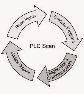
✔ Reading Inputs: The PLC reads inputs from various sensors and devices. This gives important information about the current state of the system.
✔ Processing Logic: The PLC uses this input data to execute its program logic. It makes decisions based on specific instructions and conditions set up in advance.
✔ Setting Outputs: The PLC adjusts the outputs after processing the information. This controls devices like actuators and motors, turning digital signals into real-world actions.
✔ Communication: During the scan, the PLC also handles communication tasks, allowing data to be exchanged between different components for coordinated operation. For example, the C2-NRED module can communicate with the PLC, but remember that this communication is generally slower than the PLC’s scan time.
✔ Diagnostics: Lastly, the PLC performs diagnostics during the scan. This helps it identify any errors, faults, or unusual conditions that may need immediate attention.
Understanding the PLC scan process is crucial for improving control processes and ensuring that systems operate efficiently and reliably.
C2-NRED Full Control
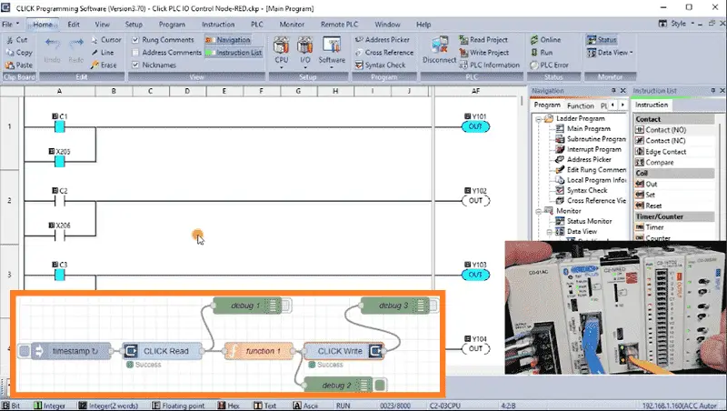
Previously, in our post “Unleash Innovation: Node-RED Flow in Click PLC,” we wrote our first flow program in the C2-NRED module. Using the Click Read and Click Write instructions, we directly read eight selector switches and wrote the status to the first eight outputs on the PLC. Our Click PLC ladder logic diagram only had an END statement, so the ladder logic diagram was not controlling the outputs.

The C2-NRED module had complete (full) control of the outputs.
In our initial setup, the flow program in Node-RED directly manipulates the outputs in the Click PLC, showcasing the power of integrated control systems.
We will modify our flow program so that the C2-NRED module and Click Ladder Logic can control the outputs. This advantage will not compromise the speed or reliability of our system. We can leverage the inherent strengths of both systems for optimal performance.
Click PLUS PLC Ladder Logic
The “Click PLUS PLC Ladder Logic” plays a crucial role in directly controlling the physical outputs of the PLC. When implementing the ladder logic, it is essential to ensure that the control of physical outputs is done directly through this logic. By utilizing the ladder logic, you can effectively manage the outputs of the Click PLC in a structured and efficient manner.
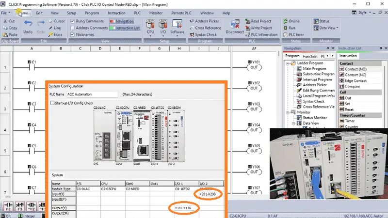
In this context, it is essential to note that any control actions using the flow program should focus exclusively on manipulating internal memory areas. These internal memory areas, such as C1 to C8, should be utilized to control the PLC outputs indirectly. By incorporating these controls in parallel with other conditions on a rung, you can effectively regulate the physical outputs of the PLC while maintaining a systematic and organized approach to programming.
Our ladder logic diagram in the Click PLC will control the first eight outputs using the internal memory areas C1 to C8. Save and transfer the ladder logic program.
Modifying the Flow Program
Turning the physical switches on the Click will no longer turn the outputs on. Our PLC scan operates quicker than the communication from our flow program, so the Click ladder logic program controls the outputs.
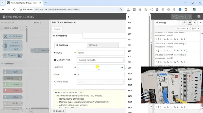
Modifying the flow program to control the internal memory bits of the Click PLUS PLC, specifically C1 to C8, is a critical step in optimizing the functionality of your PLC system. Double-click on the CLICK Write node. We will change the memory type to control relay (C) and the address to 1. The size will remain as 8. Select Done.
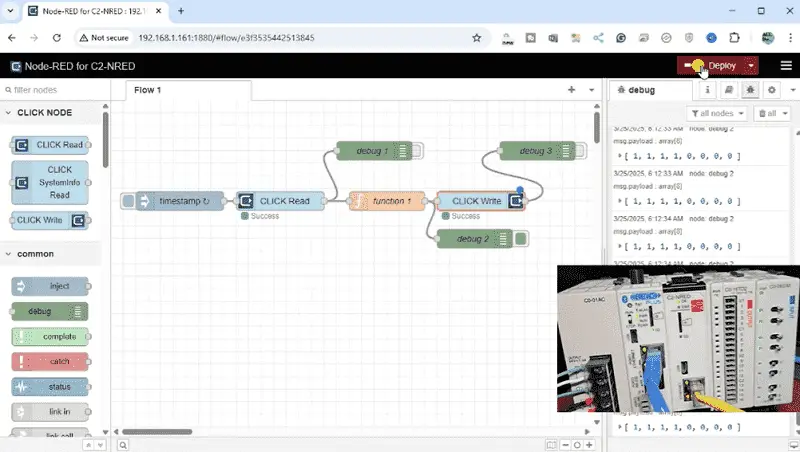
Select Deploy to save our changes and execute our modified Node-RED flow program.
When adjusting the flow program, it is essential to consider the seamless interaction between the flow program and the Click PLUS PLC Ladder Logic. This synergy ensures a synchronized operation where the internal memory bits controlled by the flow program align perfectly with the logic implemented in the ladder program.
Click PLUS PLC Ladder Logic Program
Our switches are being read from the C2-CNRED module flow program and written to the internal bits C1 to C8. The Click ladder logic program will control the outputs using these internal bits.
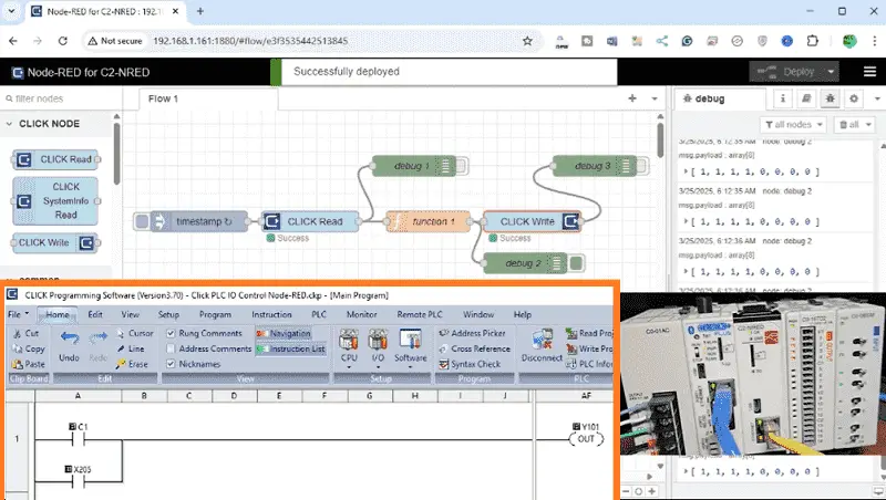
We will now add additional control from the PLC. Switch 5 to Switch 8 will also control the first four outputs. These input contacts will be programmed parallel to the existing internal bits controlled by the flow program. Save and write the program to the Click PLC.
Test the logic by activating the switches on the PLC. You will see that the flow program will turn on the outputs based on the switches’ conditions directly using internal memory. The ladder logic will also turn on the first four outputs based on the switch conditions of 5 to 8.
In this process, the seamless coordination between the flow program and the ladder logic ensures that your control actions are accurately translated into tangible results within the PLC system. This synchronization guarantees precise input and output control, optimizing the operational efficiency of your industrial processes.
The strategic modification of the Click PLUS PLC program to incorporate internal bits controlled from the flow program enables you to bridge the gap effectively between different control systems. This integration empowers you to fine-tune the behavior of the PLC, tailoring its functions to specific application requirements.
To learn more about programming the C2-NRED module with Node-RED flow programming, click here. Click here to learn more about the Click PLUS PLC.
Our Node-RED series can be found here.
Download the Click PLUS PLC Program and Flow here.
Watch on YouTube: Master Node-Red C2-NRED Control of Click PLC I/O
Node-RED Links
Node-RED Organization Home Page
Getting Started – Run Locally
Node-RED running on Windows (Run at Startup)
Securing Node-RED
Node-RED Essentials Videos (Basics of the Editor)
Learn JavaScript Free
w3schools JavaScript Tutorial
learn-js.org
Node-Red JavaScript Primer
Modbus
Node-RED Modbus TCP and Serial
Dashboard – HMI
Node-RED Dashboard
Node-RED Dashboard extra nodes
SQL Database
Node-RED SQL Database
Node-RED SQL Plus – Execute queries and stored procedures
Modbus Learning Links:
Simply Modbus Frequently Asked Questions
Modbus TCP/IP Overview – Real-Time Automation
All You Need to Know About Modbus RTU – Video
Our entire series on the Click PLC can be found here.
The Click PLC can be programmed using free Click programming software from Automation Direct.
Here is a link to the software. Version 3.70
The entire Click PLC series before the Click PLUS release can be found here.
All previous posts and information are still valid with the Click PLC lineup.
YouTube Click Playlist
YouTube Click PLUS Playlist
Click and Click PLUS PLC Overview
Click and Click PLUS PLC Videos from Automation Direct
If you have any questions or need further information, please contact me.
Thank you,
Garry
If you’re like most of my readers, you’re committed to learning about technology. The numbering systems used in PLCs are not difficult to learn and understand. We will walk through them, including Bits, Decimal, Hexadecimal, ASCII, and Floating Point.
To get this free article, subscribe to my free email newsletter.
Use the information to inform other people how numbering systems work.
Sign up now.

The ‘Robust Data Logging for Free’ eBook is also available as a free download. The link is included when you subscribe to ACC Automation.