Node-RED will be used on the Raspberry Pi 4 to communicate serial Modbus RTU to a Solo process temperature controller and Click PLC using twisted pair RS485. This will be done on the same serial network so the devices will be daisy-chained together on the two wires.
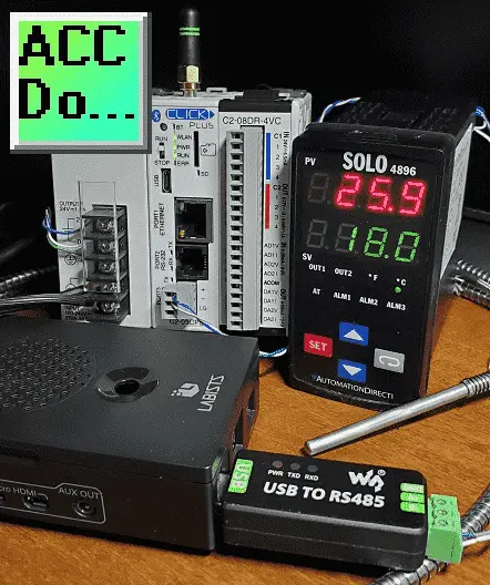
We will be reading the PV (present value) and SV (set value) of the Solo temperature controller and then writing these values into the Click PLC. An SV value will then be read from the Click PLC and if it has changed, the value will be written to the SV of the Solo controller. Let’s get started.
In this series we used Node-RED in some of the following ways:
Installing the Windows Software – Video
Modbus Communication – Video
User Interface – Dashboards – Video
SQL Database Log – Video
SQL Database Spreadsheet Connection – Video
Install Node-RED on Raspberry Pi – Video
Do-More PLC Node-RED HTTP Request – Video
Simple Click Data Logging – Video
Node-RED Modbus TCP Handling Errors –Video
Modbus RTU (RS485) Serial Network
The first thing that we will do is look at the network that we are setting up. This is an important step to ensure that addresses and unit IDs are set so there is no duplication. It will also ensure that communication parameters are known to everyone who will work with this network. A review of the serial Modbus RTU protocol can be seen at the following URL.
http://www.rtautomation.com/technologies/modbus-rtu/
https://youtu.be/OvRD2UvrHjE
| Device | Raspberry Pi – Serial Port (USB) ‘Master’ | Solo Process Controller ‘Slave’ |
Click PLC Port 3 ‘Slave’ |
Additional Devices ‘Slaves’ |
| Station Address / Unit number | N/A | 1 | 2 | … |
| Baud Rate | 9600 | 9600 | 9600 | 9600 |
| Data Bits | 8 | 8 | 8 | 8 |
| Parity | Even | Even | Even | Even |
| Stop Bits | 1 | 1 | 1 | 1 |
This table shows the master (Raspberry Pi) and the slave units. (Click PLC, Solo Temperature Controller) The maximum number of Modbus RTU slave units is 247. There can only be one serial Modbus RTU master per network. All communication is initialized by the master. Slaves will only respond to the master’s communication request.
Note: Master/Slave vs Client/Server
In a Modbus network, Client/Server terms are used usually for Modbus TCP (Ethernet). Master/Slave terms are usually used for serial communication networks. However, in recent years, depending on the manufacturer these terms are interchangeable. A Master and Client are the same and the Slave and Server are the same. Remember that the ‘S’ is the same. (Slave, Server)
Watch the video below to see the Raspberry Pi serial port programming of our serial Modbus RTU network.
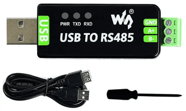
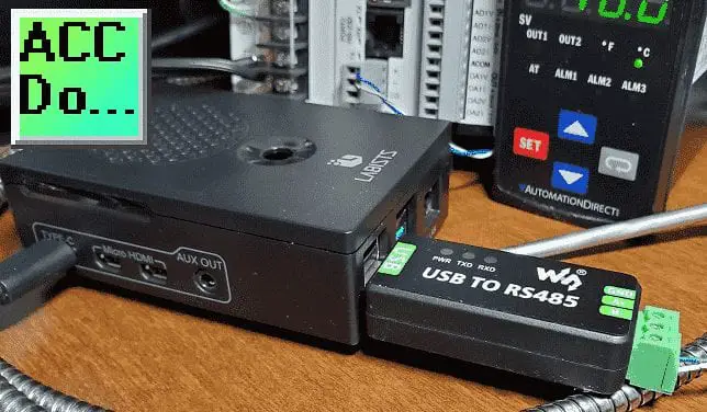
Raspberry Pi Serial Port USB to RS485 Adapter
A USB to RS485 converter will be used for the Raspberry Pi master on the serial Modbus network. We will be using the Waveshare USB to Serial adapter.
Purchase at Amazon.com
Additional information on this device can be found here.

The driver will automatically be installed when you plug in the USB to the RS485 adapter. A Raspberry Pi serial port device called ttyUSB0 can be seen in the Raspberry Pi device directory.
This USB to RS485 device has been tested on the Raspberry Pi and works well.
Amazon.com
Amazon.ca
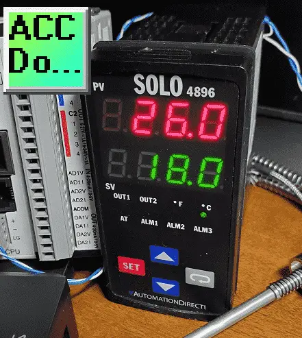
Solo Process Temperature Controller Modbus Slave Setup
The solo process temperature controller needs to be set up before we can communicate with it.
The default setting is ‘Off’ for the On-Line Configuration. Here is the way to change into the different modes in the Solo.
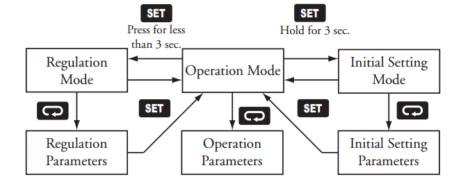
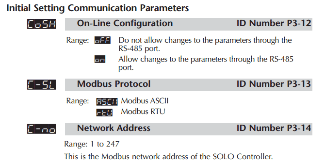
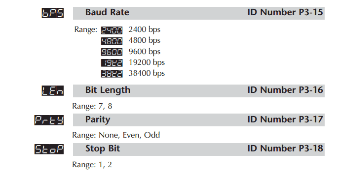
In the Initial Setting Mode we will change the on line configuration to on and make the changes to the Modbus settings as follows: 9600 Baud, Even, 8 Data Bits, 1 Stop Bit, Modbus RTU Format. We will leave the default unit number as 1. See above table.
Our controller is now set to communicate.
The Modbus addresses for the Solo process temperature controller can be found in chapter 7 of the manual.
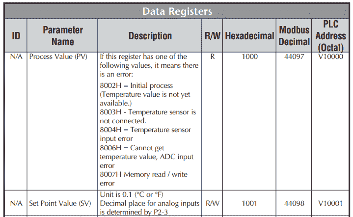
In our example, we will be reading the PV and SV values from the controller and write the SV when required. See the video below to watch this happen using Node-RED serial port Modbus RTU programming on our Raspberry Pi.
Watch the video below to see the setup of the Solo on the Mobus RTU serial network.
Download the documentation and/or configuration and monitoring software at the following URL link:
http://support.automationdirect.com/products/solo.html
Click PLC Modbus Slave Setup
The Click PLC Modbus Slave can now be set up. Our communication serial port and parameters can be seen from our table above.
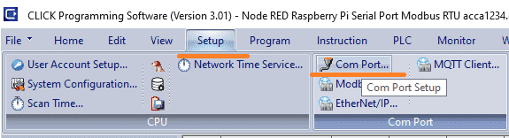
Select Com Port… from the main menu | Setup.
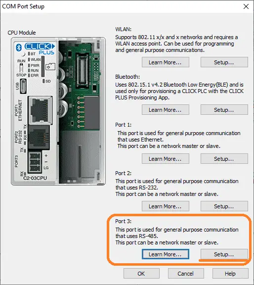
Serial Port 3 is our RS485. Select the setup button.
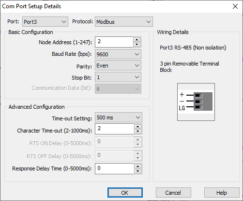
Our node address is set for 2. The parameters set to match the Solo temperature controller and chart above.
Note: The logic ground (LG) is for the shield of the twisted pair communication cable. Only connect to one of the nodes. I would use the Modbus Master (USB to RS485 adapter) logic ground to connect.
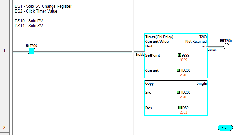
Our Click ladder logic program will move a self-resetting timer into DS2. DS1 will contain our Click Solo SV Change number. DS10 and 11 will contain the Solo PV and SV values.
Using the address picker we can see the Modbus Addresses for these locations.
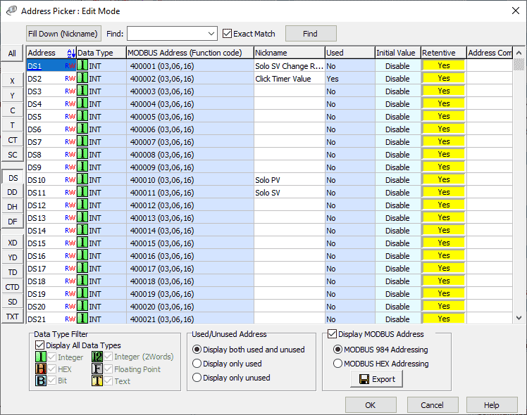
The Click Modbus addresses are offset by 1. You can see that DS1 has the Modbus address 400001.
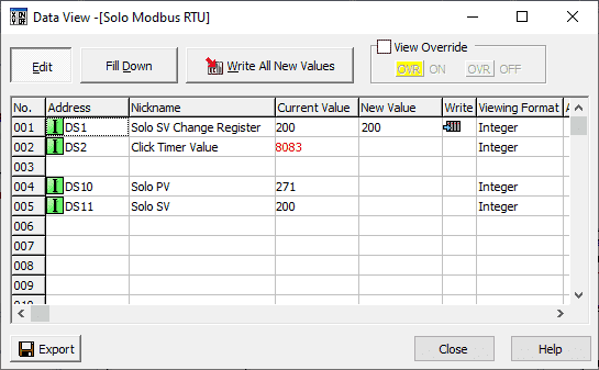
Using data view in the click programming software we can monitor and test our program. See the video below to watch the Click programming in action on our serial port Modbus RTU network.
Node-RED Serial Port Program Example
All programming communication on our serial Modbus RTU network is initiated by the master (client) on the system. This will be our Raspberry Pi running Node-RED.
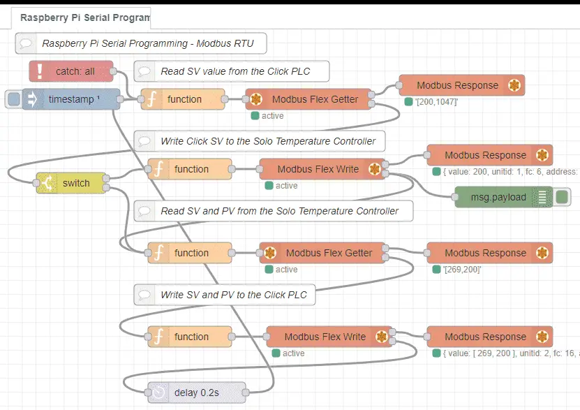
Our flow looks complicated at first, but it is easily broken down into several parts.
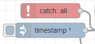
The inject node will start our program after 1 second after deployment or restart of the program. The catch node will be used to monitor for errors. Upon receiving an error this will start the process again.
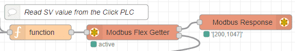
Using Modbus function code 3 for multiple registers reads we will read the SV and timer value from the Click PLC. The function node contains the following code for the read.
msg.payload = { value:
msg.payload,
'fc': 3,
'unitid': 2,
'address': 0 ,
'quantity': 2 }
return msg
The Modbus Flex Getter is used to execute the above command onto the network.
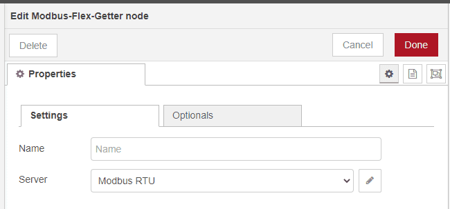
The server name we will use is Modbus RTU. This will set up the parameters that Node-RED will require to communicate on the network.
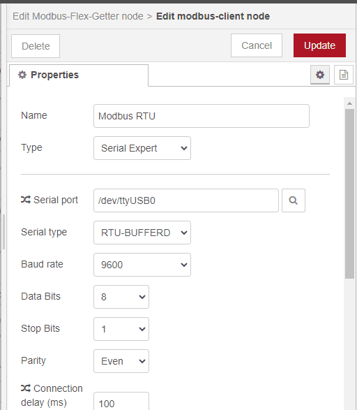
Here is where we specify our Raspberry pi serial port, type, and parameters for our network.
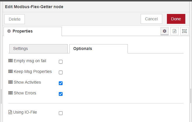
Select show activities and errors on the options tab for our Modbus Flex Getter node. This is used to detect errors so we can resume when using the catch node.
The switch node is used to determine if we need to write the Click SV to the Solo Temperature controller and then read the Solo PV and SV Modbus registers or just read the Solo PV and SV Modbus registers. If the Click SV read has not changed we will not take the time to write the value.
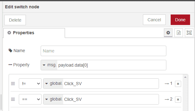
The read payload data is compared to the global Click SV value. If it is not equal then we trigger the first output. If they are equal then we trigger the second output.
If we need to write the Click SV to the Solo the Modbus Flex Write node is used. Here is the function node program to set this up.
// Save Click Set Value for Solo into a variable
global.set("Click_SV", msg.payload.data[0]);
// Set up Modbus RTU write to Solo SV
msg.payload = { value:
global.get("Click_SV"),
'fc': 6,
'unitid': 1,
'address': 4097,
'quantity': 1 }
return msg
This code will first save the Click SV as a global variable. Then we use Modbus function code 6 to write one register to our Solo SV location. Note that unit ID number 1 is used to specify the Solo.
The Modbus Flex Write options will use the same server as set above. It will also have the show activities and errors options set.
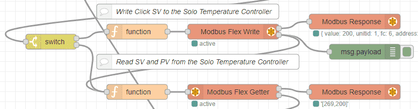
After writing to the Solo or if the Click SV has not changed we will then read the SV and PV values from the Solo temperature controller.
The function node is used to set up the Modbus Flex Getter.
msg.payload = { value:
msg.payload,
'fc': 3,
'unitid': 1,
'address': 4096,
'quantity': 2 }
return msg
Modbus function code 3 is used to read the SV and PV registers from the Solo temperature controller. The Modbus Flex Getter options will use the same server as set above. It will also have the show activities and errors options set to detect errors.
Our last sequence in our flow will use the Modbus Flex Write to write the SV and PV of the Solo into our Click PLC.
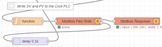
Here is the code of our function node to set up for the Modbus Flex Write node.
var values = [msg.payload.data[0], msg.payload.data[1]];
msg.payload = {
value: values,
'fc': 16,
'unitid': 2,
'address': 9,
'quantity': 2 }
return msg
The Modbus Flex Write options will use the same server as set above. It will also have the show activities and errors options set to detect errors. A delay node for 0.2 seconds is used before we start the process over again.
This is our complete Node-Red program.
Download the Click and Node-RED programs here.
Watch the video below to see the serial programming port of our Modbus RTU communications using Node-RED on our Raspberry Pi 4 Model B.
Node-RED Links
Node-RED Organization Home Page
Getting Started – Run Locally
Node-RED running on Windows (Run at Startup)
Securing Node-RED
Node-RED Essentials Videos (Basics of the Editor)
Learn JavaScript Free
w3schools JavaScript Tutorial
learn-js.org
Node-Red JavaScript Primer
Modbus
Node-RED Modbus TCP and Serial
Dashboard – HMI
Node-RED Dashboard
Node-RED Dashboard extra nodes
SQL Database
Node-RED SQL Database
Node-RED SQL Plus – Execute queries and stored procedures
Modbus Learning Links:
Simply Modbus Frequently Asked Questions
Modbus TCP/IP Overview – Real-Time Automation
All You Need to Know About Modbus RTU – Video
Watch on YouTube: Raspberry Pi Serial Port Programming
If you have any questions or need further information please contact me.
Thank you,
Garry
If you’re like most of my readers, you’re committed to learning about technology. Numbering systems used in PLCs are not difficult to learn and understand. We will walk through the numbering systems used in PLCs. This includes Bits, Decimal, Hexadecimal, ASCII, and Floating Point. To get this free article, subscribe to my free email newsletter.
Use the information to inform other people how numbering systems work. Sign up now. The ‘Robust Data Logging for Free’ eBook is also available as a free download. The link is included when you subscribe to ACC Automation.