
The Stride Field Remote I/O Modules are simple and compact. They provide an economical means to connect inputs and outputs to an Ethernet Modbus TCP communication network. Every module operates as a standalone Modbus TCP server and can be configured via a built-in web server.
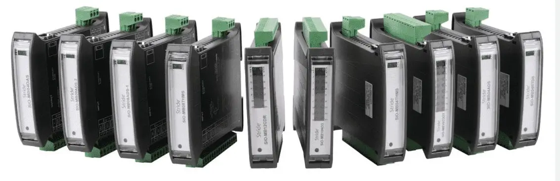
We will be looking at the following two Stride Remote IO Modules:
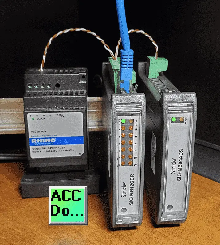
SIO-MB12CDR – Ethernet Modbus TCP Remote IO
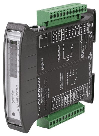
– STRIDE discrete combo remote module, Input: 8-point, 12-24 VDC, sinking, Output: 4-point, relay, (4) Form C (SPDT) relays, 2A/point, (1) Ethernet (RJ45) port(s), Modbus TCP server.
SIO-MB04ADS – Ethernet Modbus TCP Remote IO
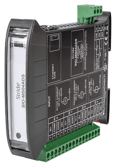
– STRIDE analog remote input module, 4-channel, current/voltage, 16-bit, isolated, input current signal range(s) of +/- 20 mA, input voltage signal range(s) of +/- 10 VDC, (1) Ethernet (RJ45) port(s), Modbus TCP server, external 20-30 VDC required.
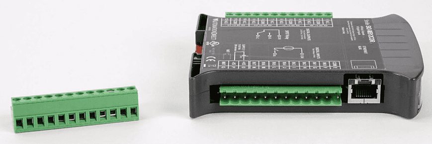
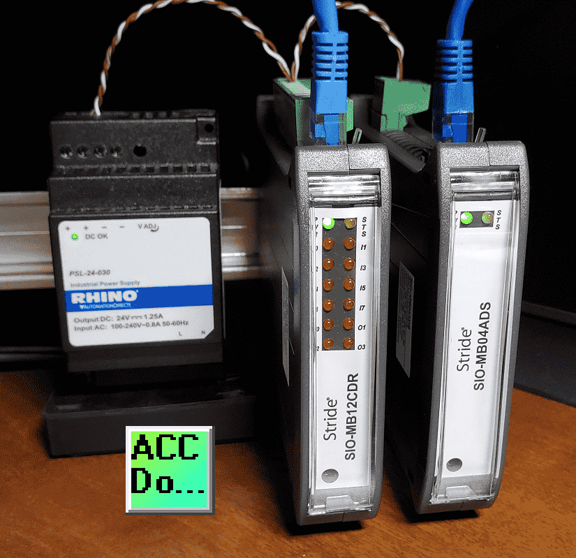
We will be unboxing both of these units. Powering and then setting them up (configuring) via the webserver. Let’s get started.
Watch the two videos below. One on unboxing our Stride Modbus TCP Ethernet remote IO and the other on powering and configuring the modules.
Features – Remote IO
• Interfaces remote I/O points to a Modbus TCP network via Ethernet 10/100 Base-T
• Analog current, voltage, resistance & temperature inputs available
• Digital inputs available
• Analog current and voltage outputs available
• Discrete relay and transistor outputs available
• Isolated power sources
• Integrated web server for status and configuration
• Remotely configurable
• Removable screw terminals
• LED status signaling
• Galvanic isolation
• IP20 rated
• –10°C to +40°C UL operating temp. (–10°C to +60°C non-UL)
• UL listed / CE mark
• DIN rail mounting
Watch on YouTube: Stride Field Remote IO Modules Unboxing SIO-MB12CDR and SIO-MB04ADS

Wiring Diagram SIO-MB12CDR – Ethernet Modbus TCP Remote IO
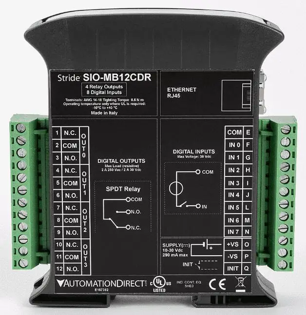
Terminal block pinouts and wiring diagrams are printed on the side of the module.
The 8 inputs are 12 to 24 VDC sinking. This means that we must supply the voltage to the input terminal. See the following post on the definition of sinking and sourcing.
Wiring 3 Wire DC NPN and PNP Sensors – Video
The 4 relay outputs are SPDT (single pole double throw). This means that each output can be wired normally open (NO) and/or normally closed (NC). The contacts are rated for 2 amps.
Wiring Diagram SIO-MB04ADS – Ethernet Modbus TCP Remote IO
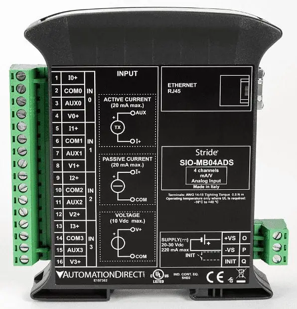
Terminal block pinouts and wiring diagrams are printed on the side of the module.
This analog input module has 4-channels. Each channel can be current and voltage. The current has a current signal range(s) of +/- 20 mA. The voltage input signal ranges are +/- 10 VDC. This makes a total of 8 inputs which consists of 4 current and 4 voltages. The resolution on the input is 16-bit which represents 65536 steps.
Modbus Addressing – Ethernet Modbus TCP Remote IO
Modbus data is mapped in tables and assigned an address. Information about the remote I/O unit can be found in this table. Data can be of two types:
• REGISTER, 2 bytes (word of 16 bits) that can be associated to an analog input or output, a variable, a setpoint, etc.
• COIL, 1 bit that can be associated with digital input or output, or to a logic state.
A register could contain the image (mirror) of a group of coils; for example, the digital inputs or outputs of a device could be read or written as individual bits addressing the coil related to each or can be read or written as a word addressing the register where each bit
corresponds to a coil. Modbus registers and coils are divided into the following groups of addresses:
• 0xxxx and 1xxxx = Coils (bit)
• 3xxxx and 4xxxx = Registers (word)
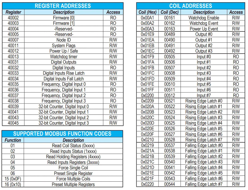
SIO-MB12CDR – Ethernet Modbus TCP Remote IO
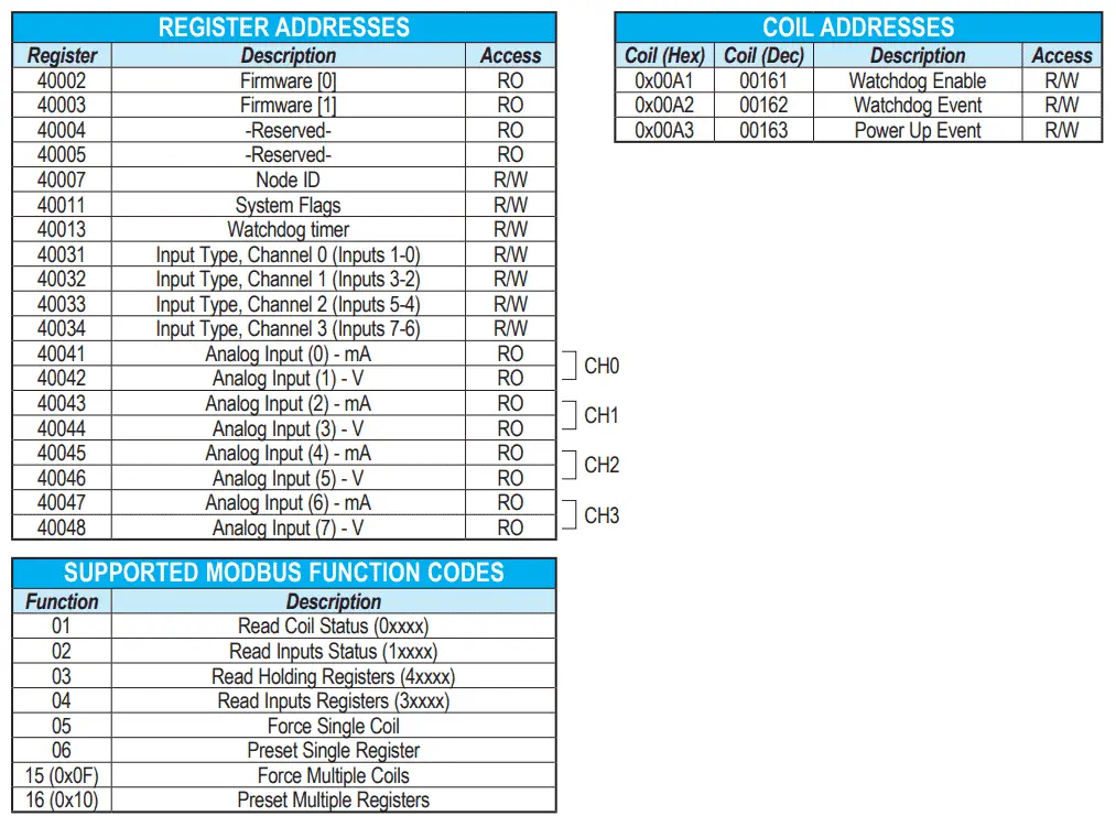
SIO-MB04ADS – Ethernet Modbus TCP Remote IO
Web Server Structure – Ethernet Modbus TCP Remote IO
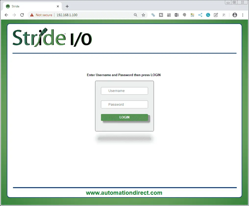
Login Screen
We access the server by opening your browser and entering the IP address of the remote I/O device. The default parameters are printed on the side of the unit.
Plugin the Ethernet cable into the SIO-MB12CDR unit. Only plug into this module because the default information is the same for both modules. Enter the default IP address printed on the side of the module into the browser.
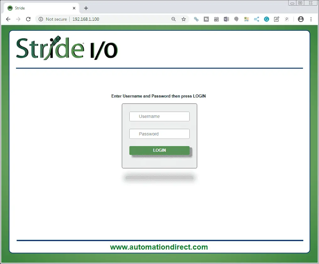
Note: In our case, we are using Google Chrome for the browser.
Default username: admin
Default password: password

Click the LOGIN button.
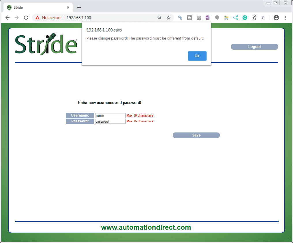
A popup window will appear asking you the change the password. The password must be different from the default. Click OK.
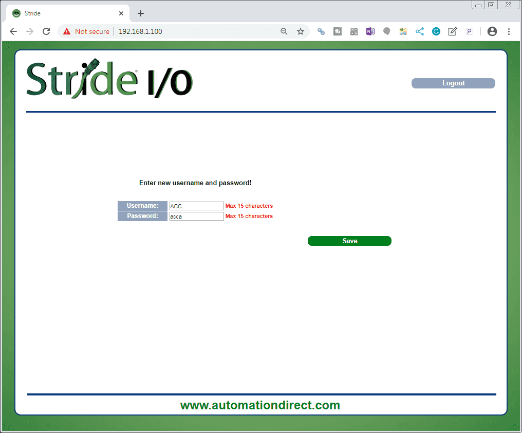
We will enter a new username of ACC and the password of acca. Select the Save button.
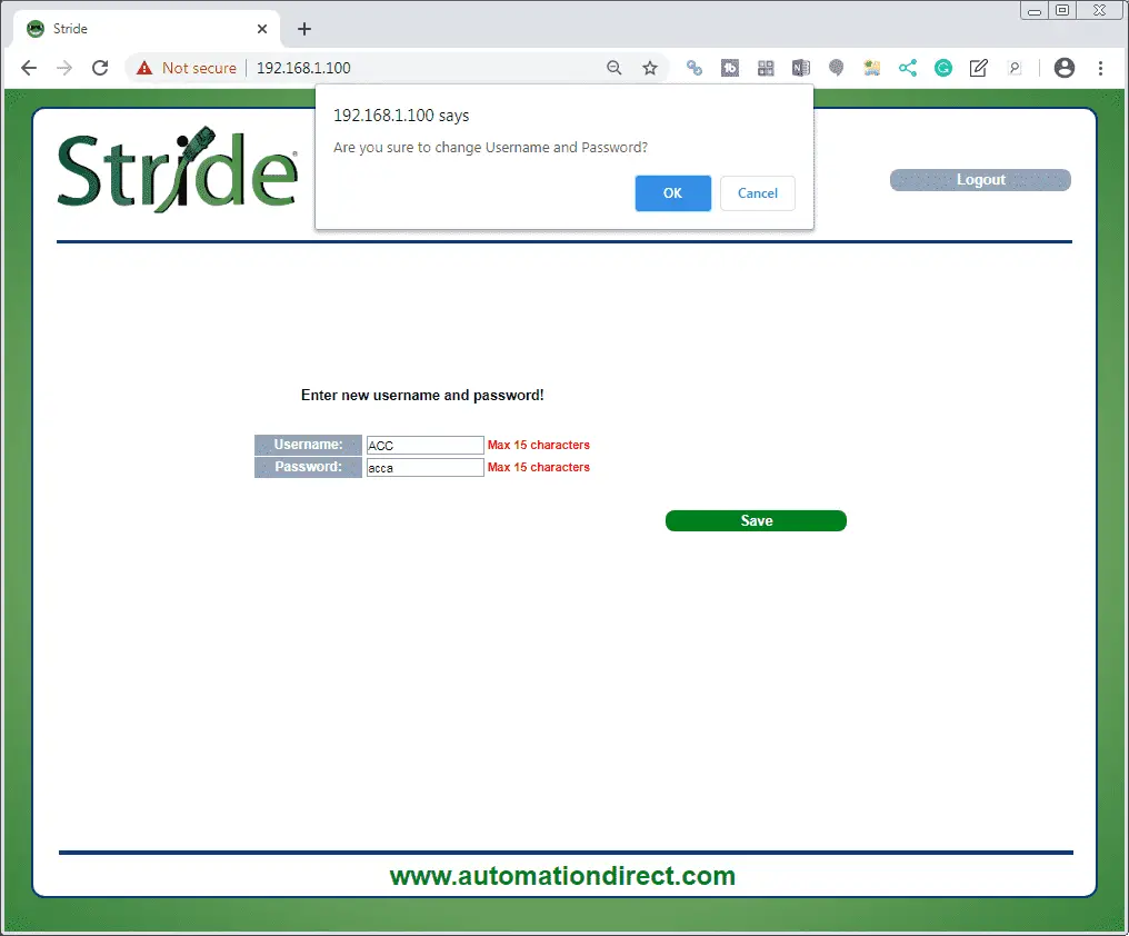
The popup will ask if you are sure you want to change the Username and Password. Select OK.
You will now be prompted again to enter the new username and password on the screen.
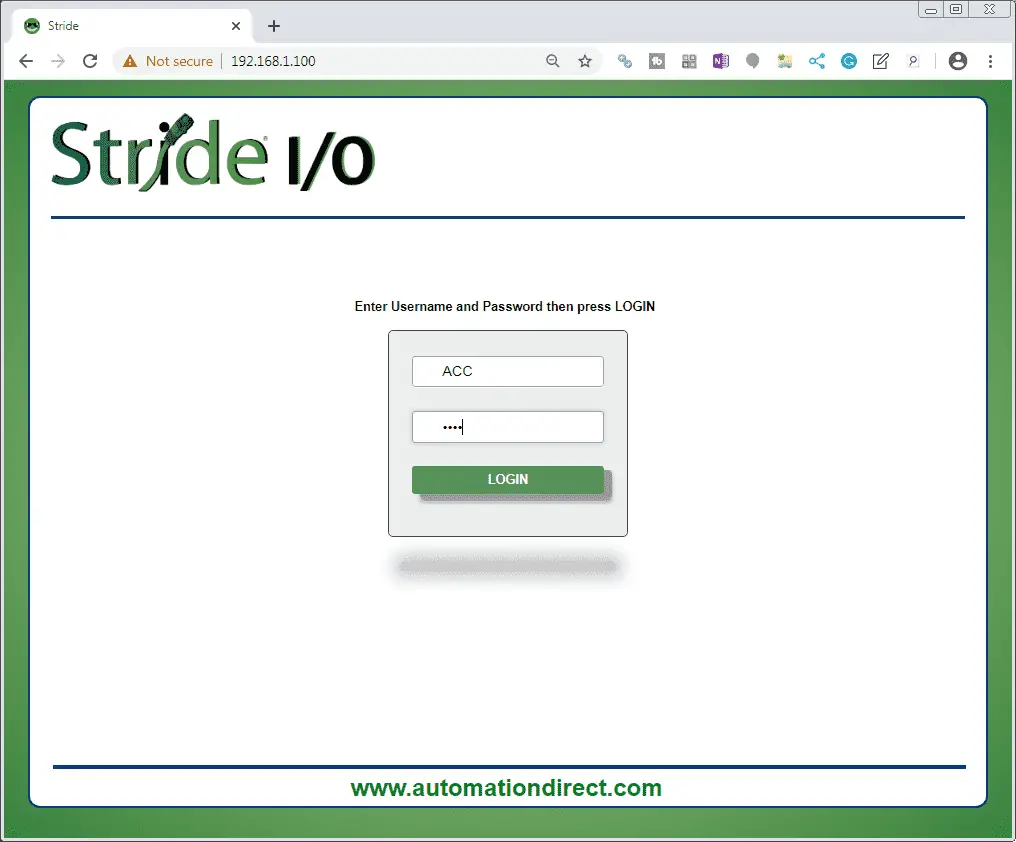
Select the LOGIN button.
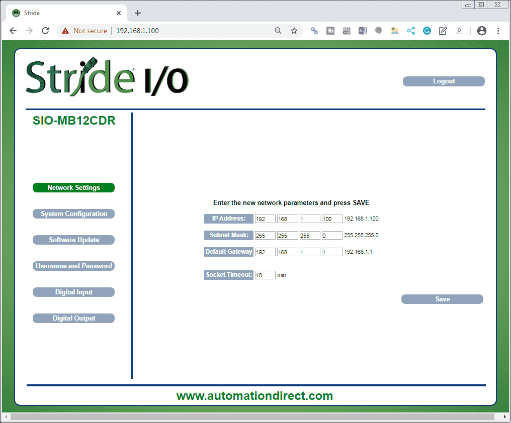
The Network Settings tab on the left side menu will be automatically selected. We will change the IP address to the last number of 131.
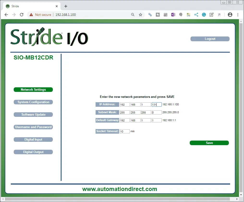
Select the Save button. This will automatically bring up the login screen again with the new IP address in the address. Enter the username and password that we set above to log back into the module. Select the System Configuration from the left side menu.
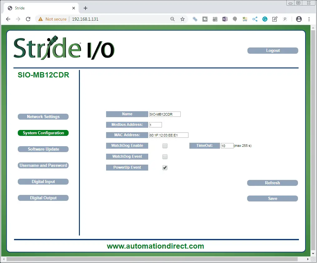
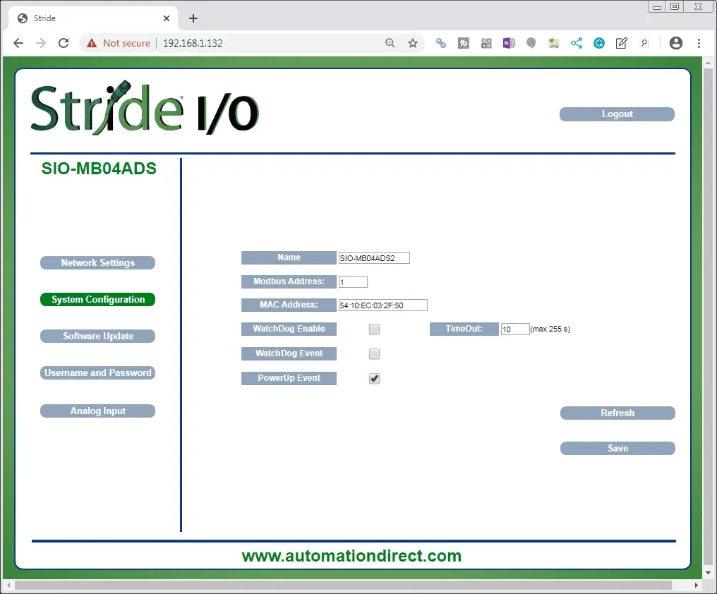
The system configuration for the module will allow you to specify the name, Modbus address, and MAC address. We will leave these as their default settings. The following parameters can also be set which will relate to the way the module will operate in your system.
WatchDog Enable: This will turn on the watchdog flag in the system registers. It will activate the watchdog timer. If a Modbus communication is not received within a time period specified then the watchdog event is triggered.
WatchDog Event: This will indicate when the watchdog event has occurred.
TimeOut: This is the time specified in seconds. The maximum time can be 255.
PowerUp Event: This bit is forced to 1 at each time power is applied to the device to indicate that the device has been switched off or reset. With the setting of this bit as 0 (by the user) and checking its state, it is possible to know if a reset of the device has occurred
(0 = reset not occurred; 1 = reset occurred). This bit must be reset manually
We will leave the above settings as their default. Select the Software Update from the left side menu.
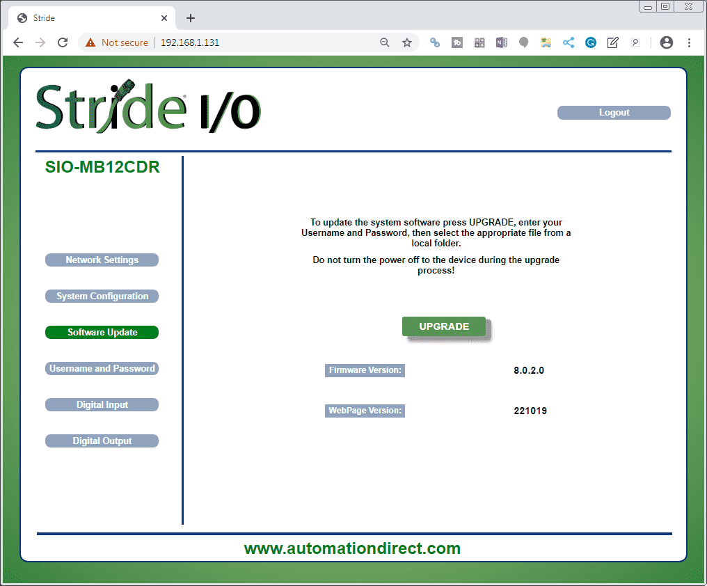
As new features are added, or modifications made, this is how we will be able to update the software in this remote IO module. Select the Username and Password from the left side menu.
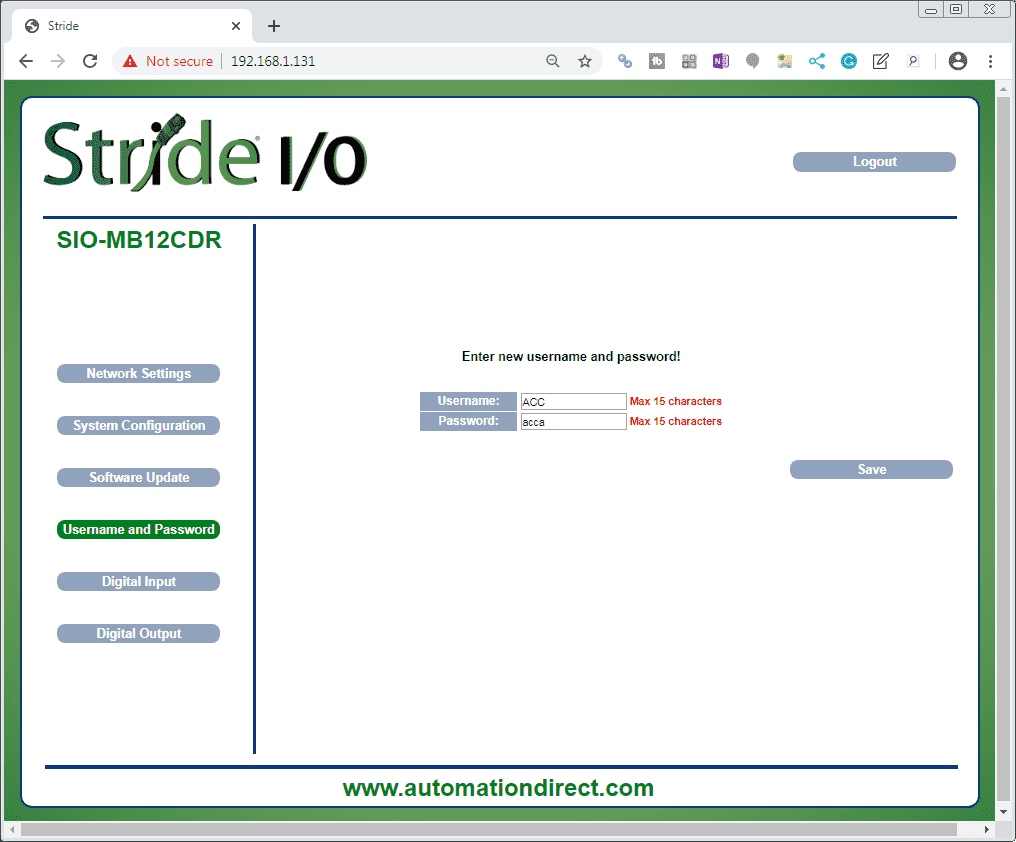
We previously were prompted to change the username and password from the default setting. Here is where we can change the information directly. Select the Digital Input button.
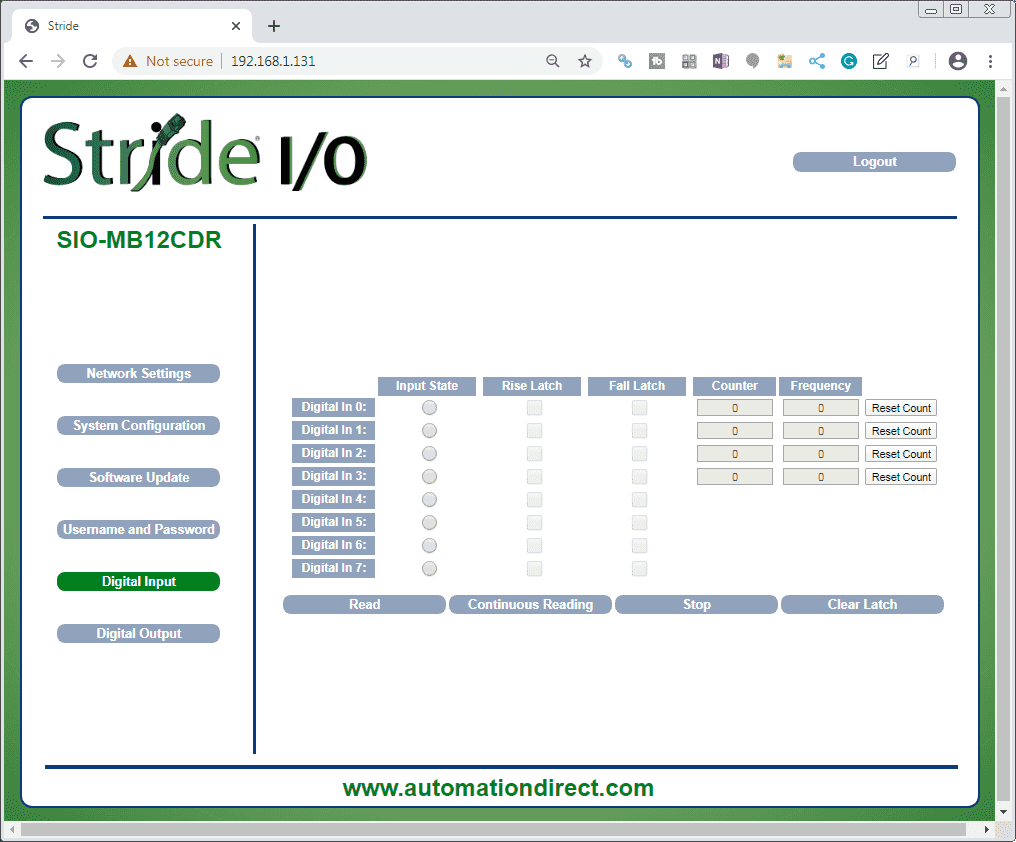
This page displays the state of the digital inputs and their associated latches.
• Read: retrieves current values for all channels (one time)
• Continuous Reading: continuously retrieves current values for all channels
• Stop: stops continuous reading
• Input State (ref. “Digital Inputs” register): indicates the state of each digital input. The indicator will be filled (red) when the digital input’s state is 1 (ON).
• Rise Latch (ref. “Digital Inputs Rise Latch” register): indicates the state of the rising edge latch for each digital input.
• Fall Latch (ref. “Digital Inputs Fall Latch” register): indicates the state of the falling edge latch for each digital input.
• Counter (ref. “32 bit Counter Digital Input” registers): indicates the current value of the counter register associated with each input.
• Frequency (ref. “Frequency Digital Input” registers): indicates the current value of the frequency register associated with each input.
• Clear Latch: resets all latches.
• Reset Count: resets the counter register associated with the digital input.
Select the Digital Output button.
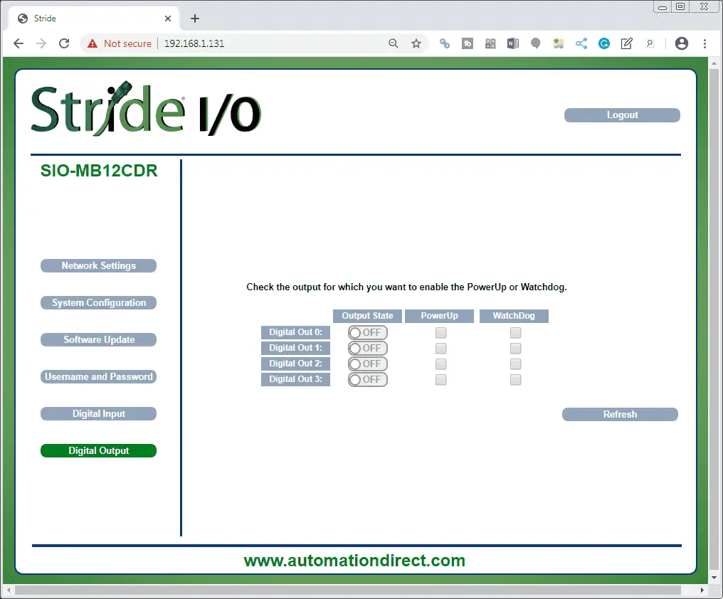
This page displays the values of and allows writing to the digital outputs, and allows configuration of the PowerUp and Watchdog settings for each output.
• Refresh: retrieves current values and updates the page display.
• Output State (ref. “Digital Outputs” register): indicates the state of each digital output. The indicator will be green when the digital output’s state is ON (logic state 1), and gray with the digital output’s state is OFF (logic state 0).
• Power Up (ref. “PowerUp/Safe” register): indicates and sets the output logic state for the Power Up event (ref. “System Flags” register).
• Watchdog (ref. “PowerUp/Safe” register): indicates and sets the output logic state for the Watchdog event (ref. “System Flags” register).
Select Logout to log out of the webpage setup.
We have now finished with the SIO-MB12CDR unit. Plugin another Ethernet cable into the SIO-MB04ADS unit. Enter the default IP address printed on the side of the module into the browser.
Using the above procedure from the SIO-MB12CDR unit we will change the username and password to the same above.
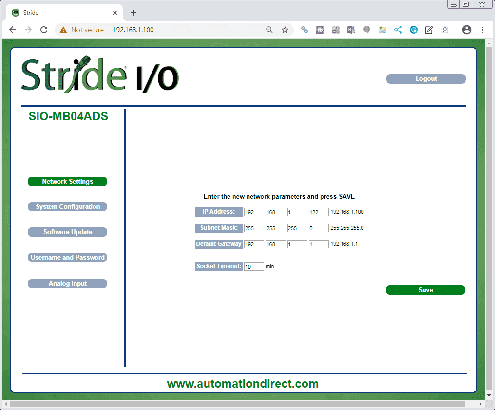
The Network Settings tab on the left side menu will be automatically selected after we change the default password and log back in. We will change the IP address to the last number of 132. Select save and then log back into the unit. Select the System Configuration button on the left side menu.
This is the same as the settings in the previous module.
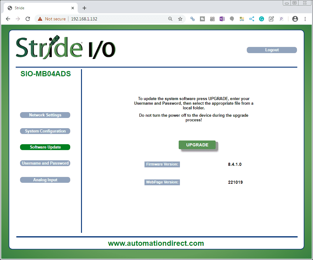
The software update screen is also the same as the above module. Since these remote input and output units are new, no updates are available yet.
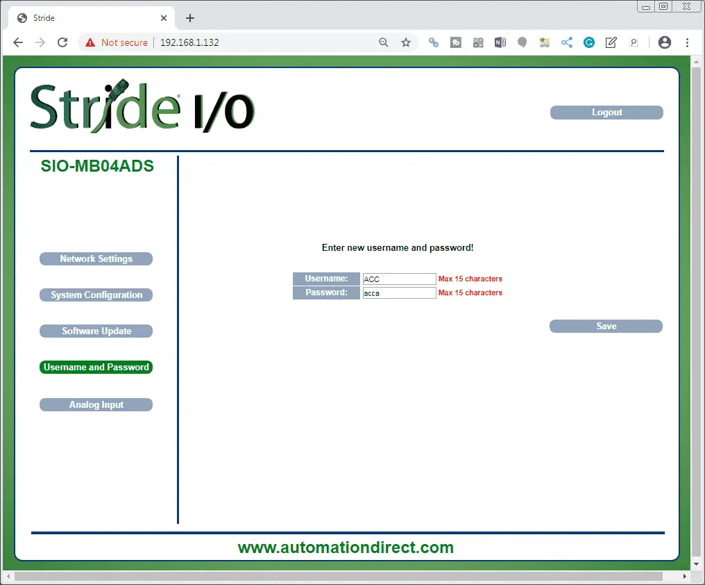
Here are the username and password screen that is the same as what we set above.
Select the Analog Input button on the left side menu.
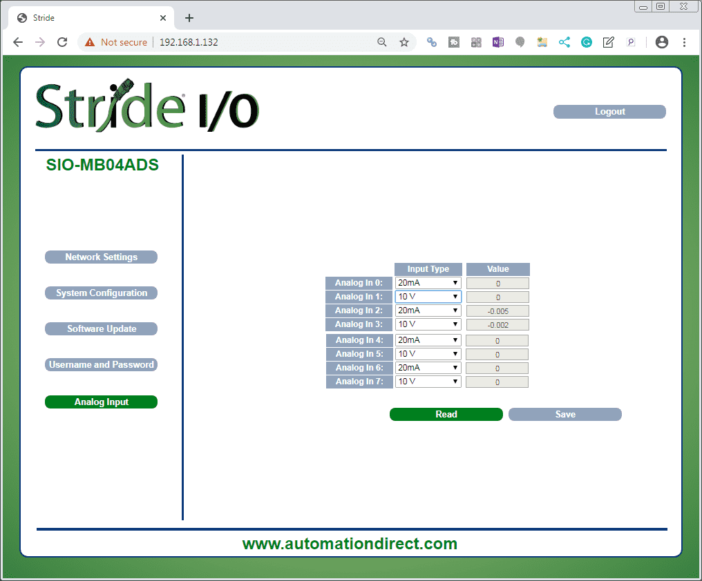
This page displays the values of the analog inputs in the unit of measurement defined by the “Input Type”. Each Input can be disabled selecting “Disabled” in the combo box under the column “Input Type”.
• Read: reads the connected Input devices and updates the Value fields.
• Input Type (ref. “Input Type” registers): shows the type of each input. Enable/Disable each Input.
• Value (ref. “Analog Input” registers): shows the value stored in the register associated with each analog input.
Click Save to save modifications to the Input Type.
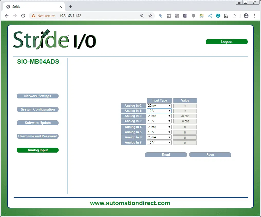
Select Logout to log out of the webpage setup.
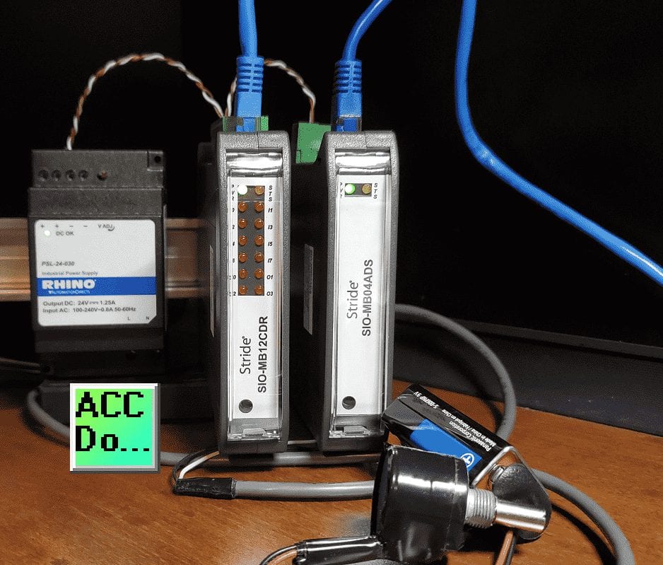
We will wire in the analog tester that we created before.
Create an Analog Voltage Input Tester for a PLC – Video
Watch the video below to see the powering and configuring of the Stride Field Remote IO Modules.
Stride Field Remote IO Modules Modbus TCP Ethernet Links:
Stride Remote Field IO Overview
Stride Field IO Modules Specifications
SIO-MB12CDR – Discrete Combination Module
SIO-MB12CDR User Manual
SIO-MB04ADS – Analog Input Module
SIO-MB04ADS User Manual
Modbus Learning Links:
Simply Modbus Frequently Asked Questions
Modbus TCP/IP Overview – Real Time Automation
All You Need to Know About Modbus RTU – Video
Next time we will be communicating with a PLC to the Stride Field Remote IO Modules Modbus TCP Ethernet.
Watch on YouTube: Stride Field Remote IO Modules Powering and Configuring
If you have any questions or need further information please contact me.
Thank you,
Garry
If you’re like most of my readers, you’re committed to learning about technology. Numbering systems used in PLC’s are not difficult to learn and understand. We will walk through the numbering systems used in PLCs. This includes Bits, Decimal, Hexadecimal, ASCII and Floating Point.
To get this free article, subscribe to my free email newsletter.
Use the information to inform other people how numbering systems work. Sign up now.

The ‘Robust Data Logging for Free’ eBook is also available as a free download. The link is included when you subscribe to ACC Automation.