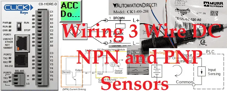
Wiring 3 wire DC sensors can be confusing. I recently received a question on PNP and NPN sensors. They wanted an explanation of what a sink is and how to wire one. Confusion over the Normally Open and Normally Closed function of the sensor is also a common question. Several diagrams will show a resistor attached to the blue wire and a load across the others, what does it all mean?
It is quite confusing sometimes the language we use for these devices. Sometimes it is the way we talk about the sensor and sometimes about the device we are connecting. (PLC)
We will break it down and go over the wiring to a PLC input. Let’s get started.
Additional component connections to PLC include the following:
Here’s a Quick Way to Wire NPN and PNP Devices
– Wiring NPN Sensor to PLC Video
– Wiring PNP Sensor to PLC Video
– Wiring Contact Discrete PLC Inputs Video
Wiring Interposing Relays
– Wiring NPN and PNP sensors into the PLC with an Interposing Relay Video
Click PLC HMI Rotary Encoder Dial Input – Video
Wiring Stack Light to Click PLC – Video
Wiring Push Buttons and Selector Switch to Click PLC – Video
– Test and Assembly of Push Buttons and a Selector Switch – Video
Wiring an Inductive Proximity NPN PNP Sensor to the Click PLC – Video
Wiring a Capacitive Proximity NPN PNP Sensor to the Click PLC – Video
Wiring an Ultrasonic Proximity Sensor to the Click PLC – Video
– Unboxing our UK1F Ultrasonic Proximity Sensor – Video
Universal Signal Conditioner and Isolator – Video
Watch the video below to see the wiring and operation of our NPN and PNP sensors to the Click PLC input.
Sinking and Sourcing?
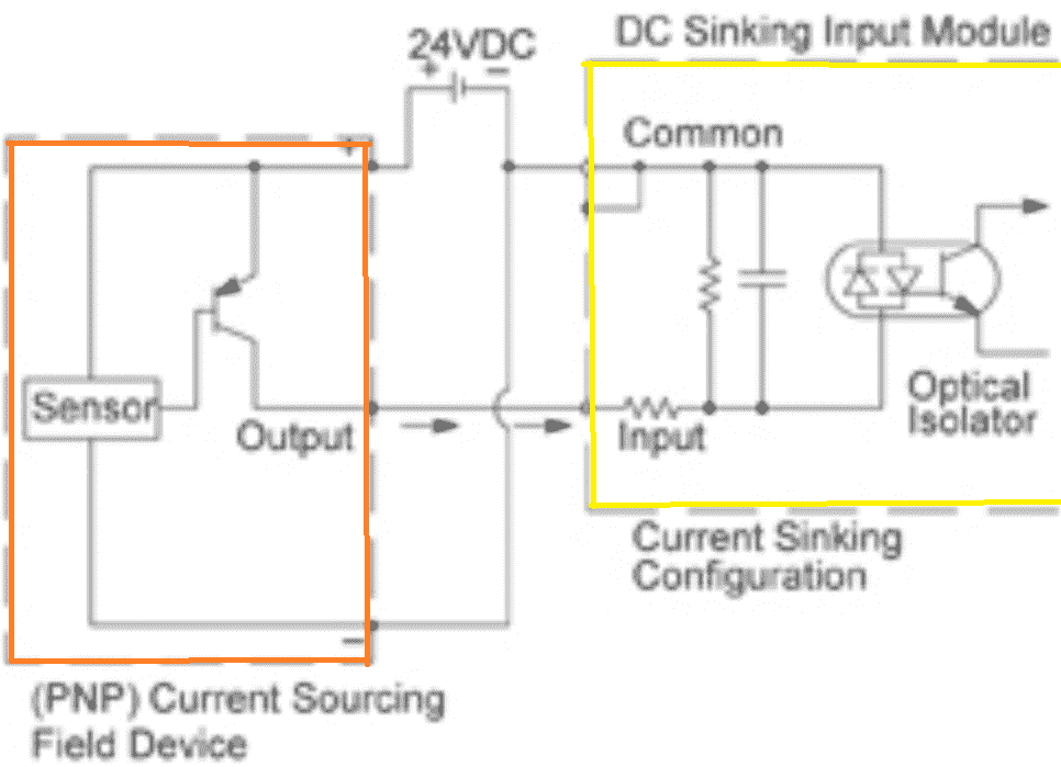
Electron flow moves from negative to positive. The amount of electron flow is the current measured in amps. ‘Conventional Current Flow’ is from positive to negative. This is used when we talk about wiring these solid-state devices.
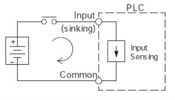
In the above diagram, you can see the arrow shows you the conventional current flow. The PLC input is sinking because we are switching to the negative supply. (Sinking the load / Negative Switching)
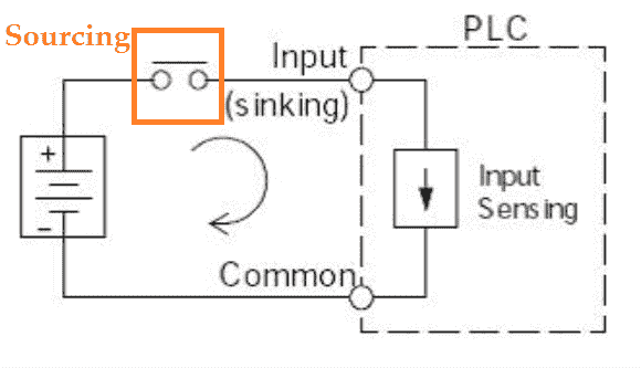
Looking at the switch, we can label this as a sourcing sensor. As you see you must determine if you are looking at sourcing or sinking from the object of interest.
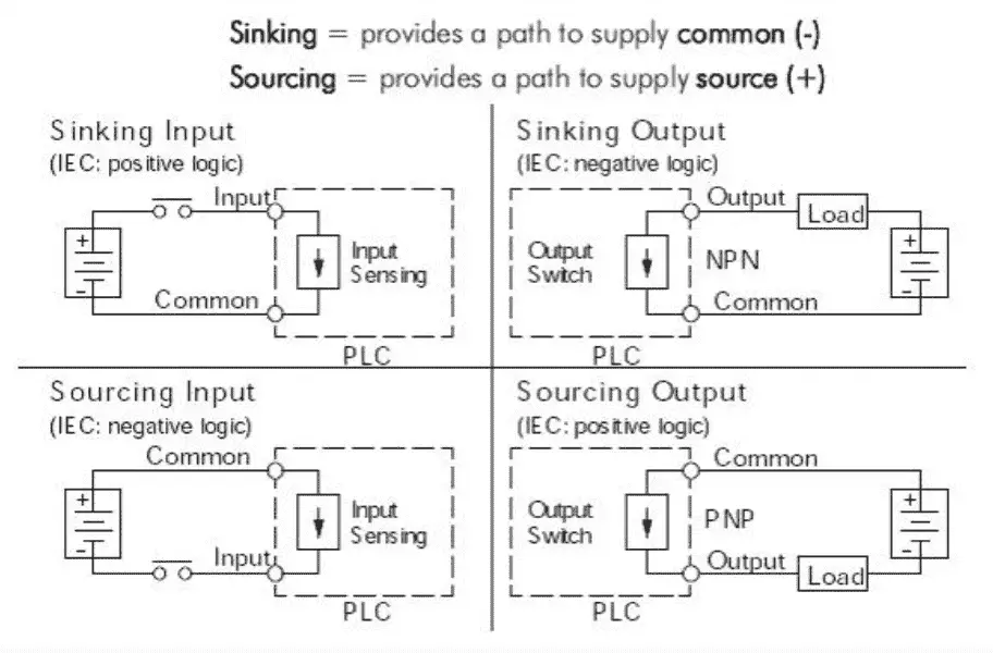
The above diagram shows sinking and sourcing PLC inputs and outputs diagrams.
Normally Open (NO) and Normally Closed (NC)?
If something is referred to as closed, then we will have current flow. Close the light switch and the light will turn on.
If something is referred to as open, then we have no current flow. Open the light switch and the light will be off.
‘Normally’ is the state that the output will be when something else is not affecting it. An example would be if a sensor is not seeing an object. The output can be normally open or normally closed.
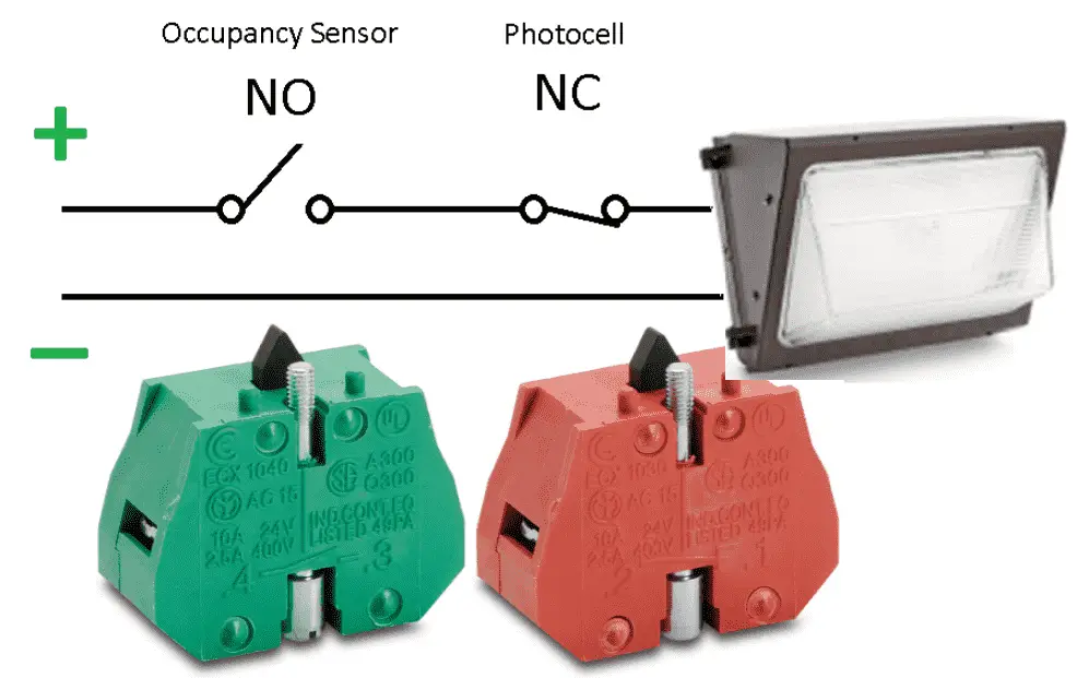
NO – Normally Open and NC – Normally Closed can be combined depending on how you want your logic to function. A high limit sensor will usually be wired in normally closed. It will open up stopping the circuit if the high limit is reached.
PLC Inputs
Most PLC inputs can be either Sinking or Sourcing per common. This is the common point on the inputs for the PLC card.
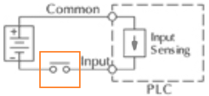
This diagram has the common of the PLC at +DC. So this is a sourcing input point. You cannot mix sourcing and sink together or you will have a short to your power supply.
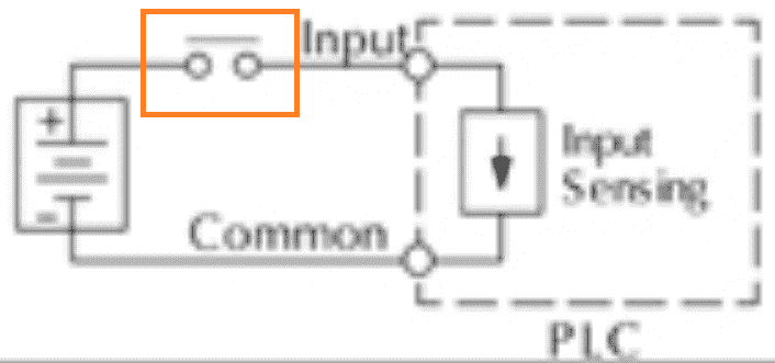
You will see in this diagram that the common of the PLC is at 0DC (-). So that will make this input a sinking input point.
See the video below to see the wiring of a senor to the Click PLC for a source as well as sink input.
NPN Wiring to our PLC – Wiring 3 Wire DC Sensors

We will replace the sourcing PLC input contact that we have shown above with an NPN sensor. The sensor output is wired to the input point of the PLC. Our sensor output, when turned on, will allow conventional current to flow back to 0DC. This can be called sinking the load or negative switching.
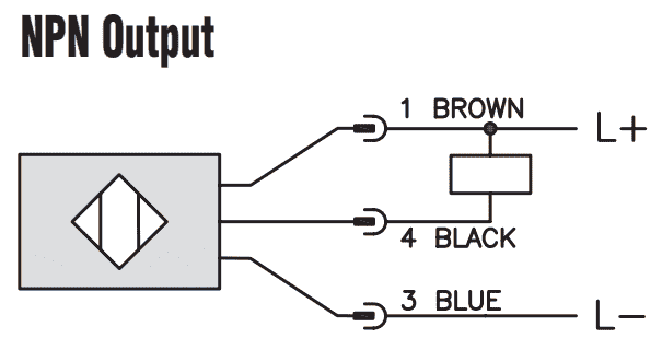
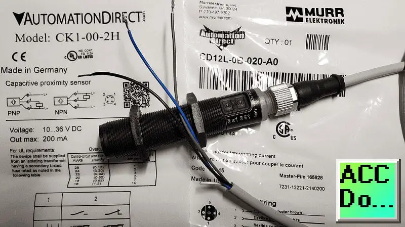
Here is a wiring diagram of an NPN sensor. This sensor is the CK1-00-2H capacitive proximity sensor. The box in the diagram represents the load. In our case, the PLC input will be our load.
PNP Wiring to our PLC – Wiring 3 Wire DC Sensors
We will replace the sinking PLC input contact that we have shown above with a PNP sensor. The sensor output is wired to the input point of the PLC. Our sensor output when turned on will allow conventional current to flow + DC to the input. This can be called sourcing the load or positive switching.
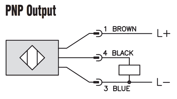
Here is a wiring diagram of a PNP sensor. This sensor is the CK1-00-2H capacitive proximity sensor. The box in the diagram represents the load. In our case, the PLC input will be our load.
Some sensors have PNP and NPN as well as NO and NC output contacts. That is why we always have to refer to the manufactures wiring diagram. The resistor that is shown in some of the diagrams is called a pull-up or pull-down resistor. This is usually internal to the sensor. Manufacturers will also show the load sometimes with a resistor.
Watch the video below to see the wiring and operation of our PNP/NPN sensor to the Click PLC input.
CK Series Capacitive Proximity Sensors Specifications
Using the Teach Functions on Sensors. NO / NC and Sensing
Watch on YouTube: Wiring 3 Wire DC NPN and PNP Sensors
Here is some additional information on wiring PLC inputs.
Wiring NPN Sensor to PLC
https://youtu.be/Z09l3HKMpqs
https://accautomation.ca/heres-a-quick-way-to-wire-npn-and-pnp-devices/
Wiring PNP Sensor to PLC
https://youtu.be/nP33k5e_Y-k
https://accautomation.ca/heres-a-quick-way-to-wire-npn-and-pnp-devices/
Wiring Contact Discrete PLC Inputs
https://www.youtube.com/watch?v=xh5dE2Z09d0
https://accautomation.ca/how-plc-inputs-work/
Wiring Stack Light to Click PLC
https://accautomation.ca/wiring-stack-light-to-click-plc/
https://youtu.be/gwDIVtNSXfs
If you have any questions or need further information please contact me.
Thank you,
Garry
If you’re like most of my readers, you’re committed to learning about technology. Numbering systems used in PLC’s are not difficult to learn and understand. We will walk through the numbering systems used in PLCs. This includes Bits, Decimal, Hexadecimal, ASCII and Floating Point.
To get this free article, subscribe to my free email newsletter.
Use the information to inform other people how numbering systems work. Sign up now.

The ‘Robust Data Logging for Free’ eBook is also available as a free download. The link is included when you subscribe to ACC Automation.