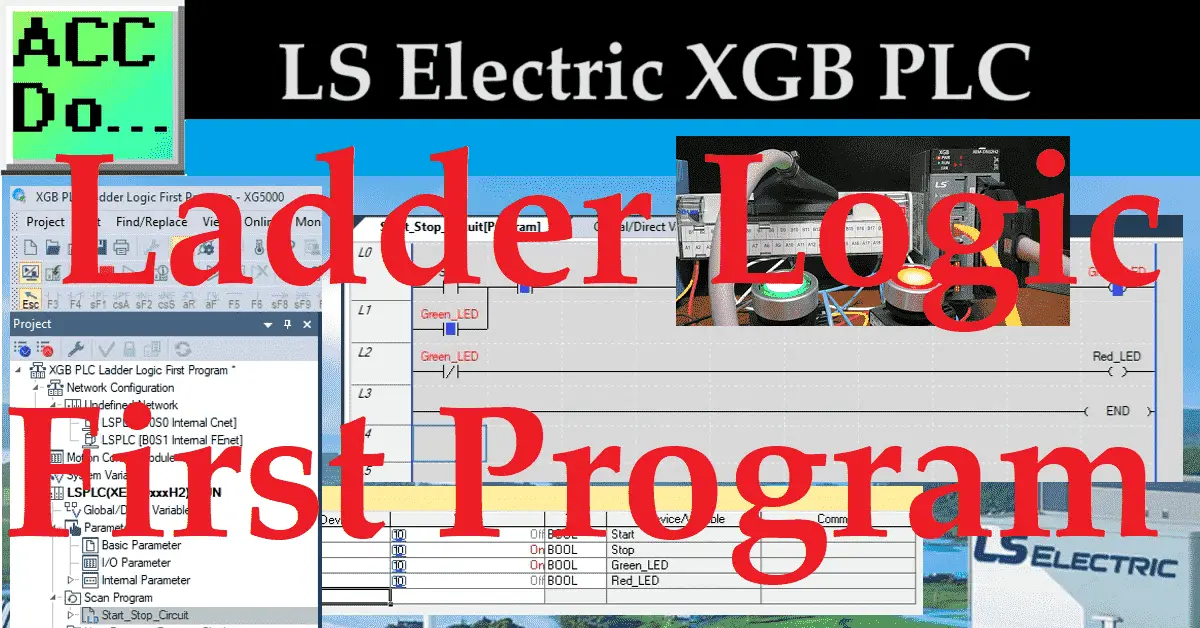
The IEC (International Electrotechnical Commission) XGB PLC, developed by LS Electric, offers a convenient programming interface using the XG5000 software in ladder diagram format. This widely used industrial PLC language is known for its simplicity and intuitiveness. The PLC can be programmed in four of the five official languages specified in the IEC standards.
Previously, a setup involving green and red-lighted pushbutton switches was integrated (wired and tested) with our LS Electric XGB PLC (XEM-DN32H2 Unit). We will continue creating, downloading, and testing a start-stop circuit using ladder logic in our controller. Monitoring the ladder logic program with the XG5000 software provides a user-friendly experience and familiar tools. Let’s get started.
Previously in this LS Electric XGB series, we have done the following:
Transform Automation with LS XGB PLC: The Solution
– Unboxing and Powering Video
Install & Com w/ XG5000 PLC – Video
LS Electric XGB PLC Variables and Scope – Video
Wiring Discrete I/O to an XGB PLC – Video
See the list of references for the XGB PLC, including the frequently asked questions (FAQ) at the end of this post.
XGB PLCs are programmable logic controllers widely used in industrial automation to control machinery and automate processes in industries such as manufacturing, automotive, and energy. Ladder logic is the most common programming language used to program PLCs. It is named after the graphical representation of the program, which looks like a ladder with two vertical rails and a series of horizontal rungs between them.
Each rung represents a specific action or condition; the logic flows from left to right and top to bottom. The conditions of the previous rung are available for the next rung of logic.
Previously, we installed the programming software on our computer and established communication to our XEM-DN32H2 controller using an Ethernet connection.
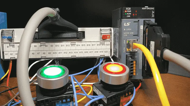
We then wired and tested green and red-lighted pushbutton switches. This ensured the wiring was correct and the PLC read the signals.
Watch the video below to see the documentation, programming, and monitoring of the ladder logic diagram start-stop circuit on the XGB PLC.
Start a New Project
Once the software is installed, begin a new project and define the hardware configuration of your PLC. Start the XG5000 programming software.
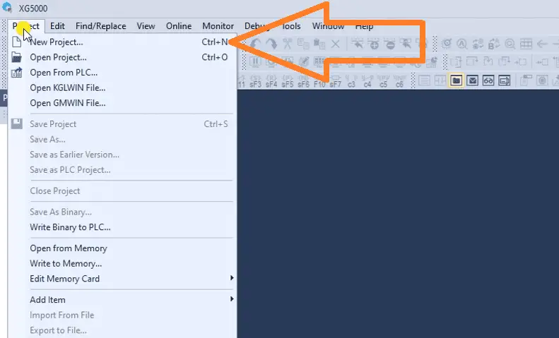
We can start a new project by selecting the icon on the main menu. This can also be done by selecting the main menu | Project | New Project or by using the shortcut combination of Ctrl + N.
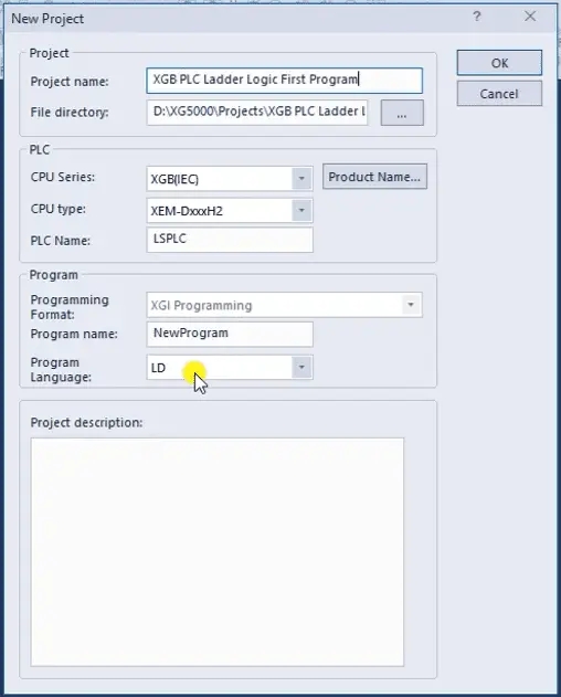
The new project window will now be displayed. Enter a name for the new project. You will see the default directory in which our program will be stored. Under the heading PLC, ensure we select the make and model of the LS Electric PLC we will be programming. This is the XGB (IEC) Series, XEM-DxxxH2 Type, and we will leave the LSPLC name as the default.
Under the program heading, we can select the program’s name and the programming language. We will leave this as the default name and ensure the language is set for Ladder Logic Diagram (LD). Select OK.
Note: As we program, ensure that you select save often. This can be done with the main page icon or main menu | Project | Save…
Assign Names to Inputs and Outputs
Documentation is a critical component of any programming language.
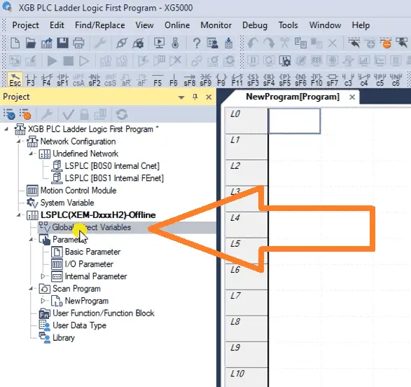
In the XG5000 programming software project window, double-click on the Global/Direct Variables under our LS PLC.
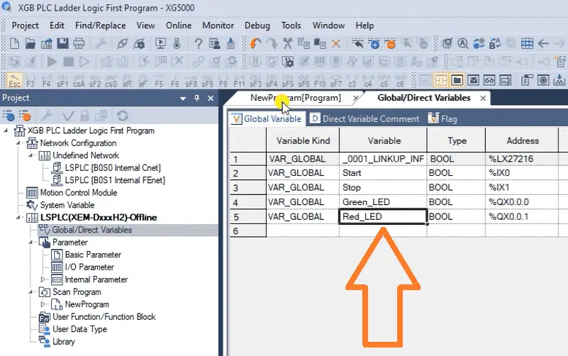
We can now enter the variables for the inputs and outputs that we wired previously to our XGB PLC.
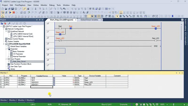
Start – %IX0 – Normally Open Input from Green Pushbutton
Stop – %IX1 – Normally Closed Input from Red Pushbutton
Green_LED – %IQ0.0.0 – Green LED on Pushbutton
Red_LED – %IQ0.0.1 – Red LED on Pushbutton
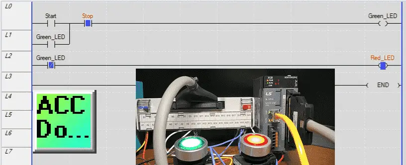
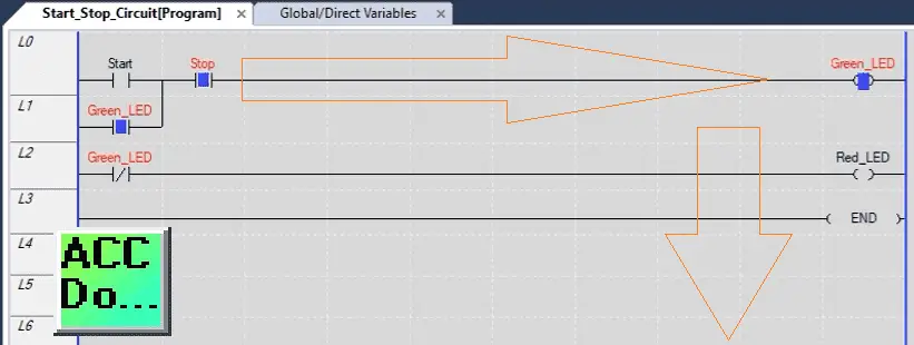
Create the Ladder Logic Diagram Program
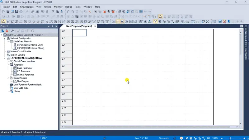
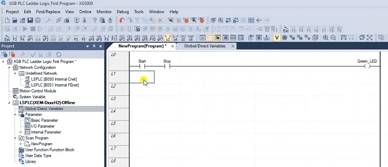
Return to our ladder logic diagram programming window. You will notice all the ladder logic diagram icons for us to use in our program.
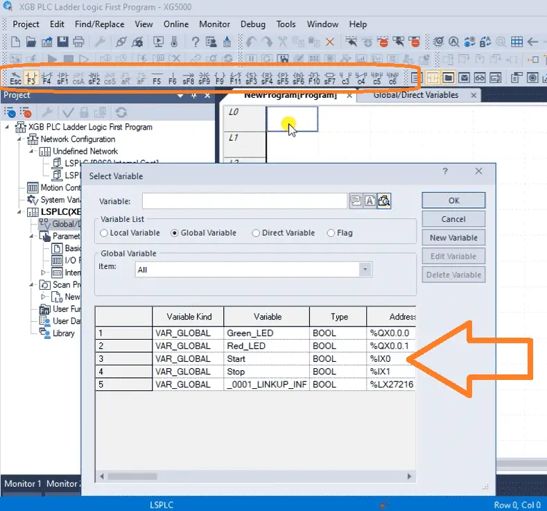
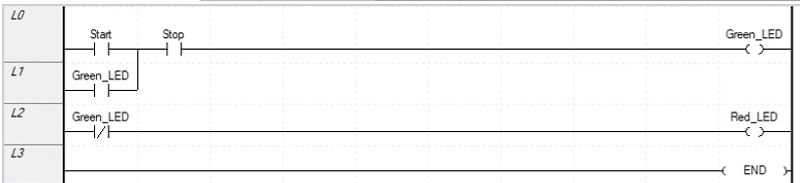
Select the F3 Normally Open Contact. Click on the workspace where you want this contact to be located. The select variable window will now be displayed. Select the start variable that we just named and select OK.
This contact will now show on our workspace.
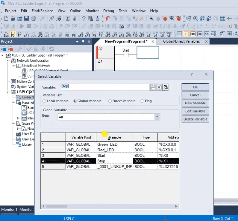
Our stop input will now be put next to our start contact. Since the stop pushbutton is wired normally closed, we will use a normally open contact.
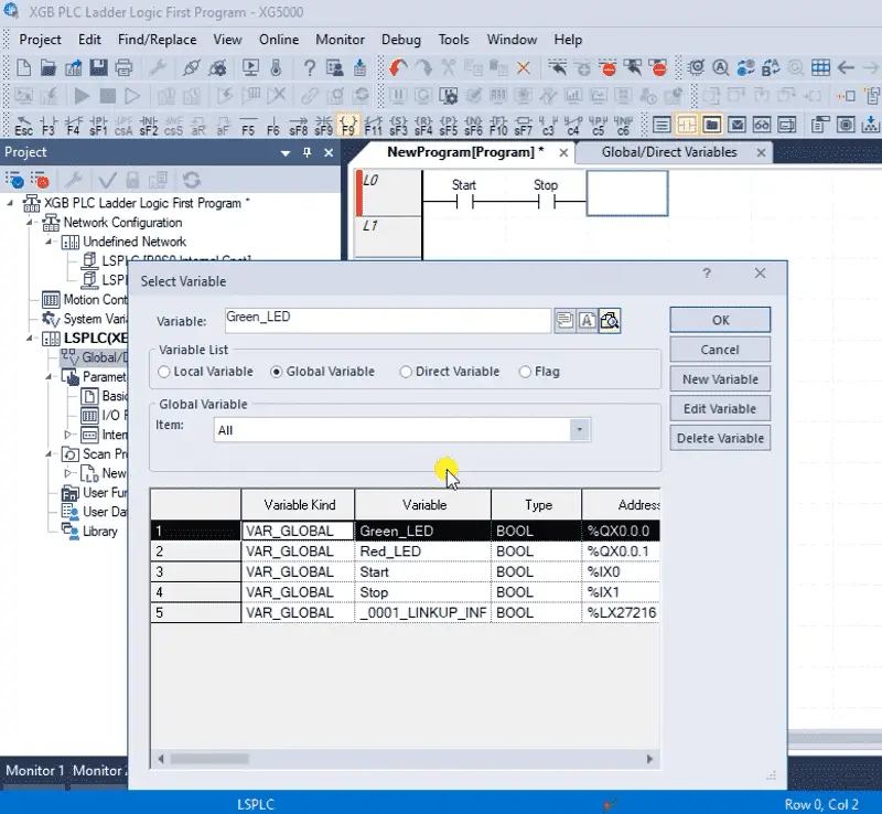
Select the output contact F9 and click on the location after the stop input.
Select the Green LED variable and OK.
This will automatically draw a line to the right-hand side of the rung.
We can place the normally open OR contact under the start contact. This will be the input for our Green LED variable.
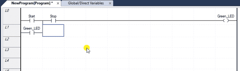
In a stop-start circuit, this is called the sealing contact. Since the start input is momentary, we must ensure the Green LED light stays on. Once the Green LED output is on, this will essentially bypass the start, and the only input to stop the output will be the stop contact.
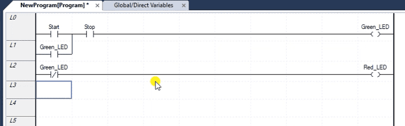
Our second rung of the ladder logic diagram code will look at the normally closed contact of the Green LED and then output the Red LED. This ensures that we have either the green or red LED light on at all times.
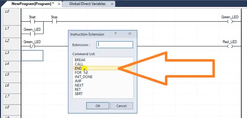
The END statement marks the end of the ladder logic diagram. It instructs the PLC to move on with the next part of the scan.
Save the program that we have just created.
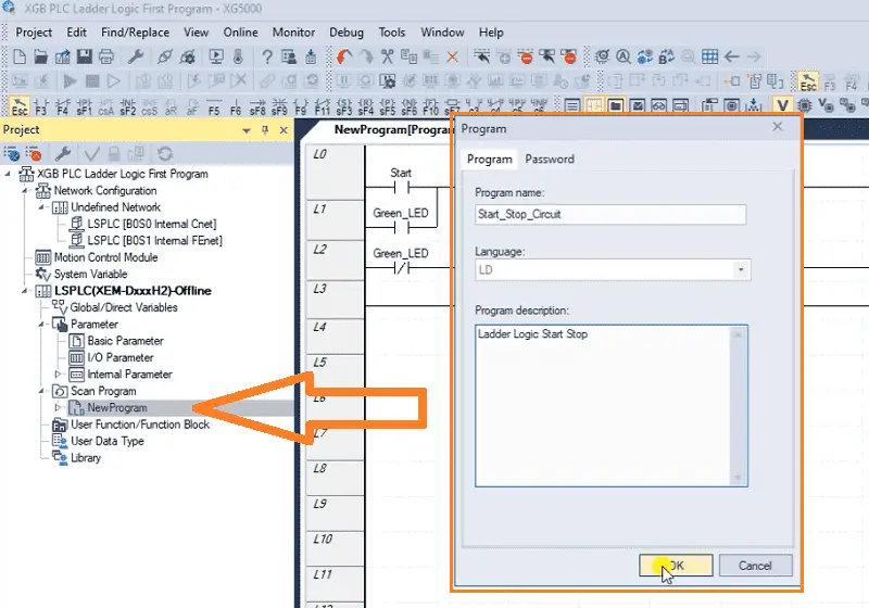
In the project window on the left-hand side of the XG5000 programming software, you will see our NewProgram under the Scan Program option. Right-click on this and select properties. The program window will now be displayed. We can enter a new name and description for our ladder logic diagram.
Transfer the Program
We will now transfer the ladder logic program to our XGB PLC.
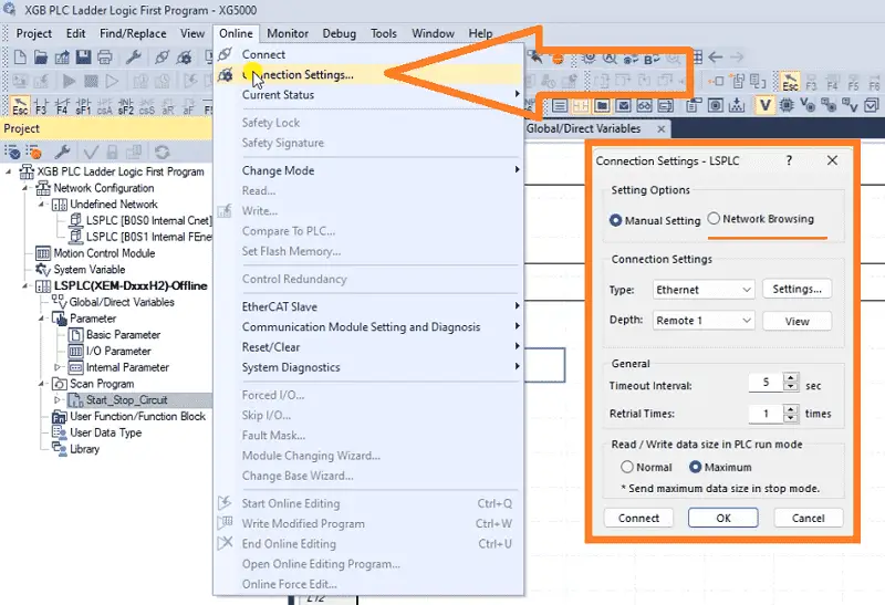
Select Connection Settings from the main menu | Online. The connection settings window will now be displayed.
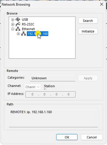
Since we do not know the IP address of the XGB PLC, select network browsing. On the network browsing window, expand the Ethernet option. This will instruct the software to look out onto the network and report back all of the IP addresses for the PLCs connected. Select the one found and select OK.
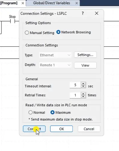
Returning to the connection setting window, we can now select connect.
The bottom of the XG5000 software will show red, indicating that the PLC has stopped scanning the program. It could also be green, indicating that the PLC is running and scanning the program.
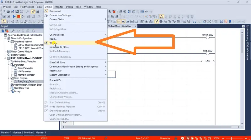
Select Write… from the main menu | Online. The write-to PLC window will be displayed. We will leave everything as their default and select OK.
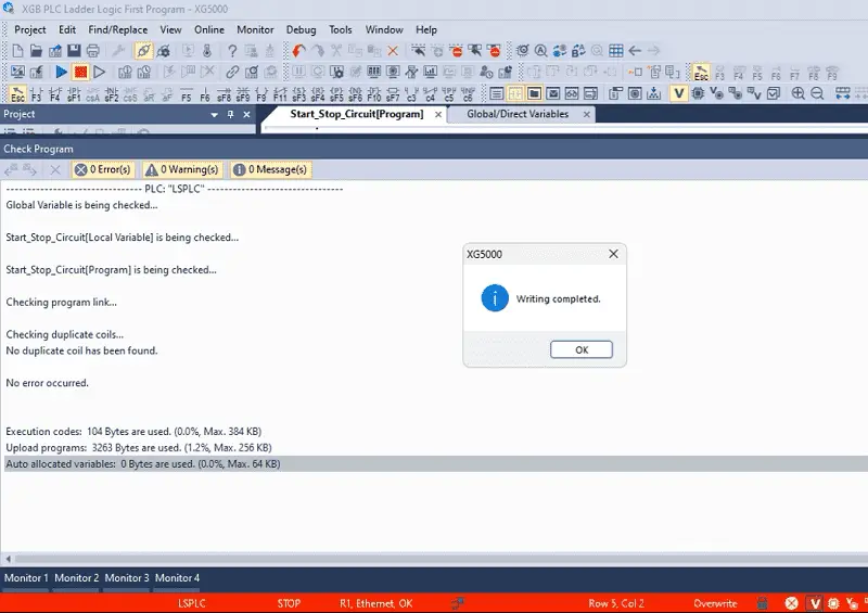
Our program will now transfer to the XGB PLC. Messages will indicate if any errors have occurred and when the writing is complete. Select OK.
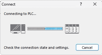
Since we changed the IP setting to the default DHCP, our IP address for the controller has changed. Connect again to the PLC using the same method we used last time.
Monitor the Program
Once connected to the PLC, change the controller’s mode to RUN. This will execute our ladder logic diagram.
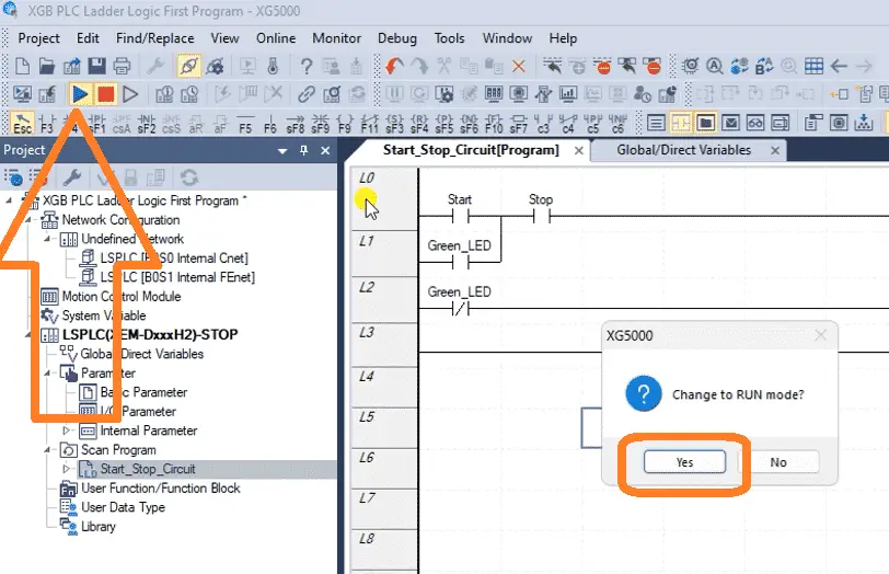
Select the run icon on the main menu. A message will be displayed asking if you want to change to run mode. Select Yes.
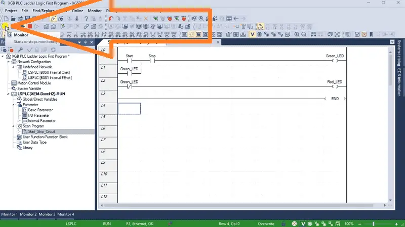
Our program is now running. Select the monitor icon on the main menu to start monitoring our ladder logic diagram in the XG5000 programming software.
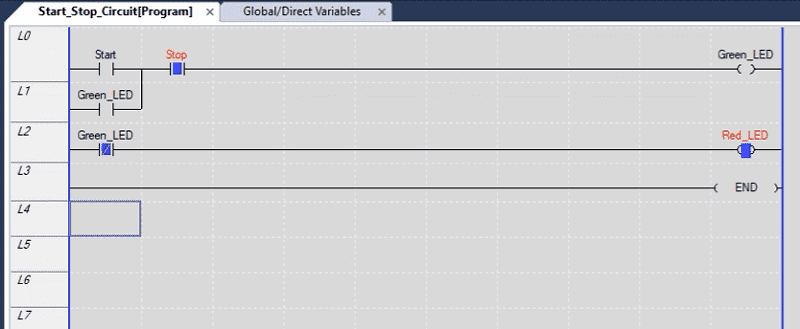
The true conditions will be displayed as solid blocks, and the label will be red.
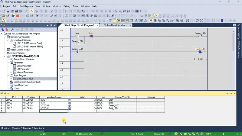
Call up Monitor 1 and enter the inputs and outputs.
Operate the pushbuttons to ensure that our start-stop circuit is working as expected. We can monitor the conditions on the ladder diagram and the monitor 1 display. This lets us catch any errors or issues before commissioning the PLC in the field.
Watch the video below to see how to program ladder logic diagram into our XGB PLC.
The XGB PLC ladder logic programming provides a powerful and intuitive way to control industrial processes and machinery. You can create sophisticated programs to automate various applications with the right software and a solid understanding of ladder logic principles. I hope this has been a helpful introduction to creating your first program using the XGB PLC ladder logic diagram.
Download our sample XGB ladder logic program here.
Watch on YouTube: XGB PLC Ladder Logic First Program
LS XGB PLC Additional Information:
LS XGB PLC – Series
– FAQ – Frequently Asked Questions
Product Cut Sheet (XEM-DN32H2 Unit Specifications)
LS PLC Technical Specifications
Manuals:
Interactive Guide
LS PLC User Manual
Other Documents:
PLC Installation Guide
Product Brochure
PLC Statement of Direction
Software and Support:
XG5000 / XG-PM PLC Programming Software
XEM PLC Firmware
Quick Start Procedures
XEM Pulse Servo Wiring Diagrams
Example Applications Directory
If you have any questions or need further information, please contact me.
Thank you,
Garry
If you’re like most of my readers, you’re committed to learning about technology. Numbering systems used in PLCs are not challenging to know and understand. We will walk through the numbering systems used in PLCs. This includes Bits, Decimals, Hexadecimal, ASCII, and Floating Points.
To get this free article, subscribe to my free email newsletter.
Use the information to inform other people how numbering systems work. Sign up now.

The ‘Robust Data Logging for Free’ eBook is also available for free download. The link is included when you subscribe to ACC Automation.